

Page 1
MANUAL
KVF-103-PF
PROCESS AUTOMATION
LAYER THICKNESS SENSOR
SCHICHTDICKENSENSOR
LAGTYKKELSESFØLER
0102
ISO9001
Page 2

LAYER THICKNESS SENSOR
With regard to the supply of products, the current issue of the following document is applicable: The General Terms of Delivery for Products and Services of
the Electrical Industry, published by the Central Association of the Electrical In-
dustry (Zentralverband Elektrotechnik und Elektroindustrie (ZVEI) e.V.) in its
most recent version as well as the supplementary clause: "Expanded reserva-
Es gelten die Allgemeinen Lieferbedingungen für Erzeugnisse und Leistungen
der Elektroindustrie, herausgegeben vom Zentralverband Elektroindustrie
(ZVEI) e.V. in ihrer neusten Fassung sowie die Ergänzungsklausel: "Erweiterter
De almene leveringsbetingelser for produkter og ydelser fra elektronikindus-
trien, der er udgivet af Zentralverband Elektroindustrie (ZVEI) e.V. i den seneste
udgave samt tillægsklasulen: "Udvidet ejendomforbehold" er gældende".
tion of proprietorship"
Eigentumsvorbehalt".
Page 3

LAYER THICKNESS SENSOR
1 Safety .............................................................................3
1.1 General .........................................................................................................3
1.2 Used Symbols..............................................................................................3
1.3 Declaration of Conformity ..........................................................................4
1.4 Intended use ................................................................................................4
1.4.1 Coding ...........................................................................................................4
1.5 Delivery, Transport and Storage.................................................................5
1.6 Installation and Commissioning................................................................5
1.6.1 Installation of the sensor ...............................................................................5
1.6.2 Installation in connection with intrinsically safe circuits .................................5
1.6.3 Sensor cable .................................................................................................6
1.7 Operation .....................................................................................................6
1.7.1 Caution - emulsions.......................................................................................6
1.8 Maintenance.................................................................................................6
1.9 Repair ...........................................................................................................6
1.10 Disposal .......................................................................................................6
1.11 Applied standards and directives..............................................................7
EN
2 Product Specifications................................................. 8
2.1 Function .......................................................................................................8
2.2 Design and dimensions..............................................................................8
2.3 Product program .........................................................................................9
3 Installation................................................................... 10
3.1 Mounting in oil/petrol separators............................................................. 10
3.2 Connection ................................................................................................ 11
204697 2007-09
EN - 1
Page 4

LAYER THICKNESS SENSOR
4 Operation......................................................................12
4.1 Emptying (disposal) of the container.......................................................12
EN
5 Maintenance and repair ..............................................13
5.1 Sensor test .................................................................................................13
6 Troubleshooting ..........................................................14
6.1 System care................................................................................................14
7 Technical specifications.............................................15
2 - EN
204697 2007-09
Page 5
LAYER THICKNESS SENSOR
Safety
1 Safety
1.1 General
The operator of the system is responsible in terms of planning, mounting, commissioning,
operating and maintenance.
Installation and commissioning of all devices must be performed by a trained professional only.
Protection of operating personnel and the system is not ensured if the product is not used in
accordance with its intended purpose.
Laws and regulations applicable to the usage or planned purpose of usage must be observed.
Devices are only approved for proper usage in accordance with intended purpose. Improper
handling will result in voiding of any warrantee or manufacturer's responsibility.
The Declaration of Conformity, Certificate of Compliance, Statement of Conformity, EC-typeexamination certificate and data sheets are an integral part of this document.
The data sheet contains the electrical data of the Declaration of Conformity, the Certificate of
Compliance and the EC-type-examination certificate.
The documents mentioned are available from http://www.pepperl-fuchs.com or contact your
local Pepperl+Fuchs representative.
1.2 Used Symbols
Safety-relevant Symbols
EN
Danger!
This symbol indicates a warning about a possible danger.
In the event the warning is ignored, the consequences may range from personal injury to death.
Warning!
This symbol indicates a warning about a possible fault or danger.
In the event the warning is ignored, the consequences may course personal injury or heaviest
property damage.
Caution!
This symbol warns of a possible fault.
Failure to observe the instructions given in this warning may result in the devices and any
connected facilities or systems develop a fault or fail completely.
204697 2007-09
EN - 3
Page 6
LAYER THICKNESS SENSOR
Safety
Informative Symbols
EN
Note!
This symbol brings important information to your attention.
Action
This symbol marks an acting paragraph.
1.3 Declaration of Conformity
All products have been developed and manufactured taking into consideration applicable
European standards and regulations.
Note!
A Declaration of Conformity can be requested from the manufacturer.
The manufacturer of this product, Pepperl+Fuchs GmbH in D-68301 Mannheim, Germany, has
a certified quality assurance system in conformity with ISO 9001.
ISO9001
1.4 Intended use
The layer thickness sensor KVF-103-PF (referred to as "sensor" in the following sections) is a
suspended sensor for detecting the oil layer thickness in oil/petrol separators.
The KVF-103-PF must always be connected to a certified intrinsically safe warning device of
the type NVOA-130, NVO-4A30, NVO5-15 or NVO5-11 (see product program).
1.4.1 Coding
Pepperl+Fuchs GmbH
68301 Mannheim/Germany
Layer thickness sensor KVF-103-PF
DEMKO 07 ATEX 142592
4 - EN
II 1G Ex ia IIB T3
204697 2007-09
Page 7

LAYER THICKNESS SENSOR
Safety
1.5 Delivery, Transport and Storage
Check the packaging and contents for damage. In the event of damage, notify the postal
service or express agent and inform the supplier.
Check the scope of supply for completeness and correctness using the order and delivery
papers.
Keep the original packaging.
The device should always be stored or transported in the original packaging.
Always store the device in a dry and clean environment. Observe the permissible storage
temperature (see data sheet).
1.6 Installation and Commissioning
1.6.1 Installation of the sensor
The sensor may be installed in potentially explosive zone 0 in accordance with Directive
94/9/EC (ATEX). The sensor must not be installed in places with potentially aggressive vapors.
The sensor and warning device must be free of voltage during installation and maintenance.
The warning device must only be connected to the supply voltage after complete mounting and
connection of the sensors.
The cable and the identification plate attached to it are elements of the product. The cable must
not be shortened to such an extent that the identification plate is removed. The identification
plate must not be removed.
EN
The sensor has IP68 protection and is weather- and oil-resistant. It can therefore be installed in
oil/petrol separators.
When installing the device in oil/petrol separators, observe the permissible ambient
temperature in the range from -20 °C...60°C (253 K ... 333 K).
1.6.2 Installation in connection with intrinsically safe circuits
Installation of the intrinsically safe power circuits of the devices is permitted in potentially
explosive zones, whereby, in particular, safe separation from all non-intrinsically safe power
circuits must be guaranteed.
The intrinsically safe current circuits must be installed according to valid setup regulations.
For the interconnection of the intrinsically safe field devices and the intrinsically safe power
circuits of the associated devices, the respective maximum values of the field device and the
associated device with regard to explosion protection must be observed (proof of intrinsic
safety). EN 60079-14/IEC 60079-14 must be observed.
204697 2007-09
EN - 5
Page 8

LAYER THICKNESS SENSOR
Safety
1.6.3 Sensor cable
Sensor cables must not be installed in cable or conductor bundles together with other current
circuits. Avoid installing sensor cables parallel to other cables that may transmit interfering
EN
1. 7 O p e r a t i o n
1.7.1 Caution - emulsions
1.8 Maintenance
signals, which impair the sensor signal and thus the alarm function. The sensor itself must not
be grounded.
If you extend the sensor cable, observe the applicable ATEX specifications with regard to color,
quality and constancy. Use an unscreened cable with a conductor size of 1 mm².
An oil/petrol separator is a device for separating oil from water. Situations may arise in which
the oil can not be separated because an emulsion has formed. An emulsion is a relatively
stable mixture of oil and water. Sensors can not detect oil if emulsions with a high water content
have formed. Always contact the oil/petrol separator manufacturer if there is any doubt as to
whether the oil has been separated from the water before the liquid is drained to the sewage
system.
For operation of oil/petrol separators, there may be standards, directives or laws that define
regular system or sensor tests. Check the operation of the sensor at least twice a year and
more frequently in the event of unfavorable environmental conditions.
When the oil/petrol separator is being emptied (disposal), the sensor must always be washed
and dried. The sensor must not be cleaned with caustic fluids. A badly contaminated sensor
can trip a wrong alarm or, in certain circumstances, fail to trip an alarm.
1.9 Repair
The devices may not be repaired, changed or manipulated. If there is a defect, the product
must always be replaced with an original part.
1.10 Disposal
Disposal of devices and their packaging material must be performed in compliance with the
applicable laws and guidelines of the corresponding country.
The devices do not contain batteries which need to be disposed of separately from the
products.
6 - EN
204697 2007-09
Page 9

LAYER THICKNESS SENSOR
Safety
1.11 Applied standards and directives
EN 50014
EN 50020
EN 50178
EN 60079-14
EN 61000-6-2
EN 61000-6-3
ATEX Directive 94/9/EC
EMC Directive 89/336/EEC
Low Voltage Directive 73/23/EEC
EN
204697 2007-09
EN - 7
Page 10
LAYER THICKNESS SENSOR
Product Specifications
2 Product Specifications
2.1 Function
EN
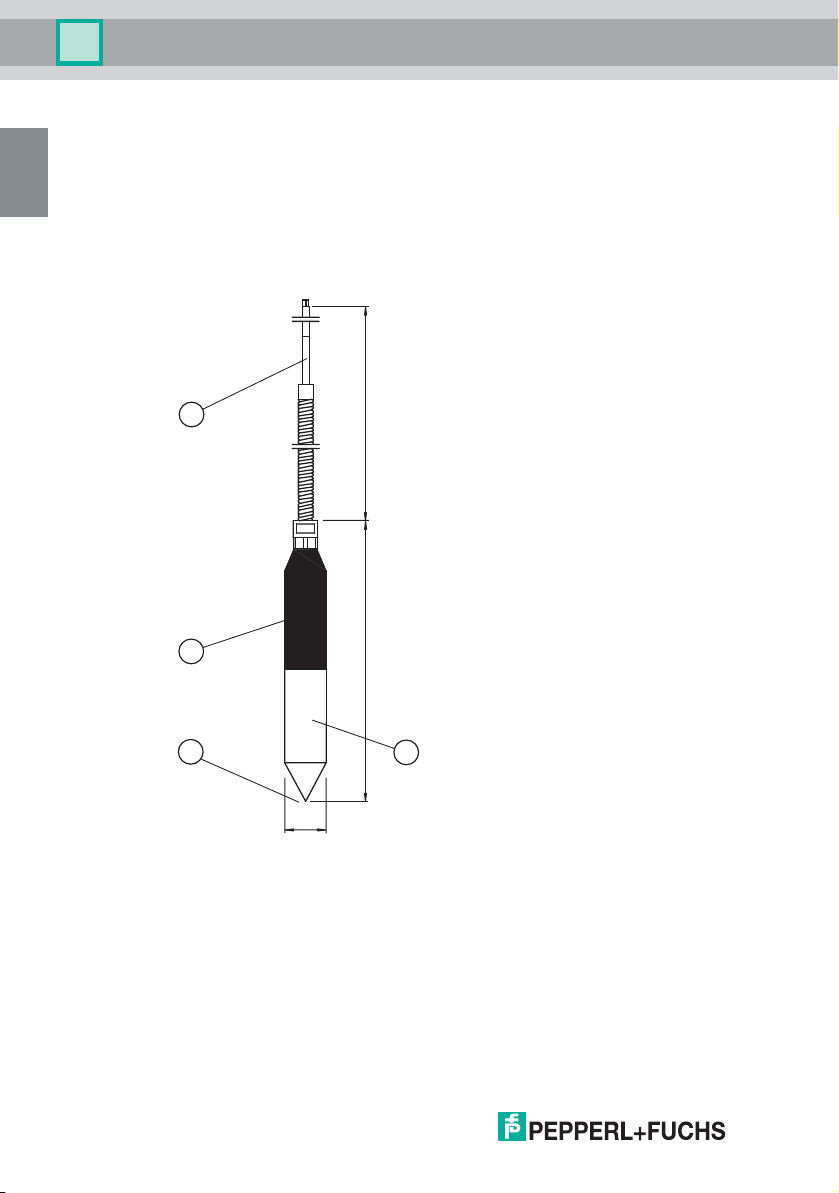
2.2 Design and dimensions
The sensor has an integrated electronic circuit which, via an oscillator circuit, emits a weak HF
signal that changes depending on whether the sensor element is surrounded by water or by
oil/air. The sensor is capable of distinguishing between air and water, and between water and
oil, but not between air and oil.
4
3
2
Ø33
1 Lower section
2 Switch point
3 Upper section
4 Cable with identification plate
5000
210
1
8 - EN
The sensor has a 5 m long, oil-resistant cable (4), on which the identification plate is located.
204697 2007-09
Page 11
LAYER THICKNESS SENSOR
Product Specifications
2.3 Product program
Warning devices
Description Type code
Intrinsically safe relay, 230 V AC (discontinued) NVOA-130
Intrinsically safe relay, 230 V AC (discontinued) NVO-4A30
Intrinsically safe relay, 230 V AC (discontinued) NVO5-15
Intrinsically safe warning device, 230 V AC NVO5-11
Sensors
Description Type code
Overflow sensor for detecting excessively high fluid level NVF-104/34-PF
Overflow sensor for detecting excessively high fluid level NVFRH-125E
Layer thickness sensor for detecting thickness of oil layer KVF-103-PF
Accessories
Description Type code
Cable connector IP67 for one sensor NVO5-SK3
Mounting set for one sensor NVO5-B
Housing with DIN rail NVO5-KV
EN
204697 2007-09
EN - 9
Page 12

LAYER THICKNESS SENSOR
Installation
3 Installation
3.1 Mounting in oil/petrol separators
EN
Read the chapter on Safety and, in particular, the section on Installation and commissioning
(see chapter 1.6.1)before connecting the sensor. Do not remove the identification plate.
Warning!
Risk of short circuit
Injuries and damage to the device are possible when working with live parts.
• Before working on the device, always disconnect the supply voltage.
• Connect the device to the supply voltage only after completion of the work.
During installation, observe the instructions of the oil/petrol separator manufacturer. Always
ensure that the sensor suspension device remains constantly at the correct height. If possible,
ensure that the suspension device is mounted in a location that can be reached from the
separator access shaft so that it is possible to raise the sensor during separator emptying
(disposal) or maintenance of the oil/petrol separator.
An exact height adjustment is made with the mounting set. For securing in a concrete
container, use mounting set NVO5-B supplied with the equipment. For containers, tanks or
separators made of other materials, e. g. plastic or metal, use other appropriate means of
mounting (screws and dowels).
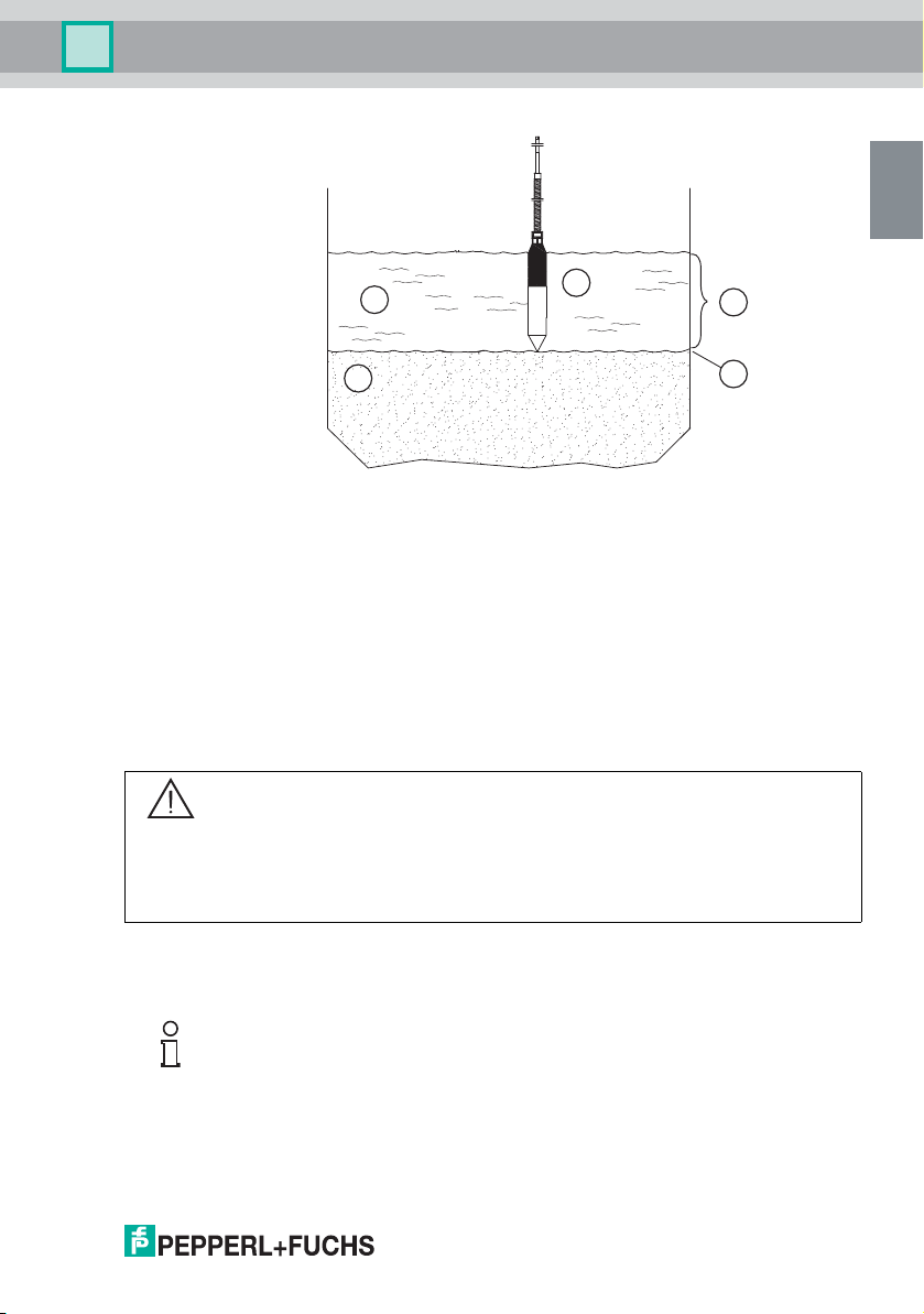
When the liquid level is correct, the sensor must be submerged a few centimeters into the
liquid. Exactly how far it is submerged depends on the type of the oil/petrol separator, the
design and the capacitance. The sensor must be suspended above the liquid. The switch point
(see chapter 2.2, dimension drawing, position 2) of the sensor is located at the tip of the sensor.
This means that the tip of the sensor must be installed at the height specified as the maximum
layer thickness.
10 - EN
204697 2007-09
Page 13
LAYER THICKNESS SENSOR
Installation
EN
1 Layer thickness
2 Alarm level
3 Sensor KVF-103-PF
4 Water
5 Oil
3.2 Connection
Read the chapter on Safety and, in particular, the section on Installation and commissioning
(see chapter 1.6.1) before connecting the sensor. Do not remove the identification plate.
Warning!
Risk of short circuit
Injuries and damage to the device are possible when working with live parts.
• Before working on the device, always disconnect the supply voltage.
• Connect the device to the supply voltage only after completion of the work.
5
4
3
1
2
When making the connection, ensure the polarity of the sensor cables is correct. The loop
resistance of the extension cable should not exceed 20 Ω for the sensor.
Note!
For additional information on connecting the sensors to the warning device, refer to the manual
of the warning device NVO5-11.
204697 2007-09
EN - 11
Page 14
LAYER THICKNESS SENSOR
Operation
4 Operation
4.1 Emptying (disposal) of the container
EN
The sensor is a sensitive component. Therefore always observe the following safety
information during emptying (disposal):
Caution!
Malfunction or damage through mechanical stress of the sensor.
In case of nonobservance, the safety and operation of the sensor or the entire alarm system is
not guaranteed.
• Before emptying (disposal) the oil/petrol separator, remove the sensor from the container.
• Protect the sensor against impacts, knocks and unnecessary tensile forces in the cable.
• Insert the sensor in the oil/petrol separator only after it has been filled.
12 - EN
204697 2007-09
Page 15
LAYER THICKNESS SENSOR
Maintenance and repair
5 Maintenance and repair
5.1 Sensor test
Frequency of the test
The sensor is maintenance-free. However, to ensure the proper function of the entire alarm
system, test the function of the sensor at least twice a year, or more frequently under difficult
ambient conditions.
Checking the normal situation
1. Remove the sensor from the oil/petrol separator.
2. Wash and dry the sensor.
3. Hold the sensor in your hand.
The "SYSTEM OK" LED lights up or flashes on the warning device.
Checking the alarm situation
1. Remove the sensor from the oil/petrol separator.
2. Wash and dry the sensor.
3. Suspend the sensor freely in midair.
The "ALARM" LED lights up and an acoustic signal (if present) sounds.
Note!
For additional information on the alarm signals via LED, refer to the manual of the warning
device NVO5-11.
EN
204697 2007-09
EN - 13
Page 16

LAYER THICKNESS SENSOR
Troubleshooting
6 Troubleshooting
6.1 System care
EN
Contaminated sensors can trip incorrect alarms. Clean, in particular, the sensor tips with fat
dissolving cleaning agent to remove all oil, petrol and other contamination residue.
14 - EN
204697 2007-09
Page 17

LAYER THICKNESS SENSOR
Technical specifications
7 Technical specifications
Power supply Rated voltage 18 V DC
Ambient conditions Ambient temperature -20 °Cto60°C
Mechanical data Protection class IP68
Connection cable
Material stainless steel
Cable 5 m
Mass approx. 1000 g
Dimensions ∅33 mm x 210 mm
Data for application in
conjunction with hazardous
areas
Voltage U
Current I
Power P
Internal capacitance C
Internal inductivity L
Max. internal capacitance C
for extension cable
Max. internal inductivity L
for extension cable
(253 K to 333 K)
i
i
i
i
24 V
400 mA
1.6 W
60 nF
i
0.2 mH
0.1 µF
i
0.3 mH
i
EN
204697 2007-09
EN - 15
Page 18

LAYER THICKNESS SENSOR
Notes
16 - EN
204697 2007-09
Page 19

SCHICHTDICKENSENSOR
1 Sicherheit....................................................................... 3
1.1 Allgemeine Sicherheitshinweise................................................................3
1.2 Verwendete Symbole ..................................................................................3
1.3 Konformitätserklärung ................................................................................4
1.4 Bestimmungsgemäße Verwendung...........................................................4
1.4.1 Kennzeichnung.............................................................................................. 4
1.5 Lieferung, Transport und Lagerung...........................................................5
1.6 Installation und Inbetriebnahme................................................................5
1.6.1 Installation des Sensors ................................................................................5
1.6.2 Installation in Verbindung mit eigensicheren Kreisen.................................... 5
1.6.3 Sensorkabel ..................................................................................................6
1.7 Betrieb..........................................................................................................6
1.7.1 Auftreten von Emulsion .................................................................................6
1.8 Wartung........................................................................................................6
1.9 Reparatur .....................................................................................................6
1.10 Entsorgung ..................................................................................................6
1.11 Angewandte Normen und Richtlinien........................................................7
DE
2 Produktspezifikationen ................................................8
2.1 Funktion .......................................................................................................8
2.2 Aufbau und Abmessungen.........................................................................8
2.3 Produktprogramm .......................................................................................9
3 Installation................................................................... 10
3.1 Montage in Öl-/Benzin-Abscheideranlagen ............................................ 10
3.2 Anschluss ................................................................................................. 11
204697 2007-09
DE - 1
Page 20

SCHICHTDICKENSENSOR
4 Betrieb ..........................................................................12
4.1 Entleeren (Entsorgen) des Behälters.......................................................12
5 Wartung und Reparatur ..............................................13
5.1 Sensorprüfung...........................................................................................13
6 Störungsbeseitigung...................................................14
6.1 Anlagenpflege............................................................................................14
DE
7 Technische Daten........................................................15
2 - DE
204697 2007-09
Page 21

SCHICHTDICKENSENSOR
Sicherheit
1 Sicherheit
1.1 Allgemeine Sicherheitshinweise
Die Verantwortung hinsichtlich Planung, Montage, Inbetriebnahme, Betrieb und Wartung liegt
beim Betreiber der Anlage.
Die Installation und Inbetriebnahme aller Geräte darf nur durch eingewiesenes Fachpersonal
durchgeführt werden.
Der Schutz von Betriebspersonal und Anlage ist nicht gewährleistet, wenn die Baugruppe nicht
entsprechend ihrer bestimmungsgemäßen Verwendung eingesetzt wird.
Die für die Verwendung bzw. den geplanten Einsatzzweck zutreffenden Gesetze bzw.
Richtlinien müssen beachtet werden. Die Geräte sind nur für eine sachgerechte und
bestimmungsgemäße Verwendung zugelassen. Bei Zuwiderhandlung erlischt jegliche
Garantie und Herstellerverantwortung.
Die entsprechenden Datenblätter, Konformitätserklärungen und/oder EGBaumusterprüfbescheinigungen sind ein integraler Bestandteil dieses Dokumentes. Das
Datenblatt enthält die elektrischen Daten der EG-Baumusterprüfbescheinigung.
Diese Dokumente finden Sie auf www.pepperl-fuchs.com oder wenden Sie sich an Ihren
lokalen Pepperl+Fuchs-Vertreter.
1.2 Verwendete Symbole
Sicherheitsrelevante Symbole
DE
Gefahr!
Dieses Symbol kennzeichnet eine unmittelbar drohende Gefahr.
Bei Nichtbeachten drohen Personenschäden bis hin zum Tod.
Warnung!
Dieses Zeichen warnt vor einer möglichen Störung oder Gefahr.
Bei Nichtbeachten drohen Personenschäden oder schwerste Sachschäden.
Vorsicht!
Dieses Zeichen warnt vor einer möglichen Störung.
Bei Nichtbeachten können Geräte oder daran angeschlossene Systeme und Anlagen bis hin
zur völligen Fehlfunktion gestört werden.
204697 2007-09
DE - 3
Page 22

SCHICHTDICKENSENSOR
Sicherheit
Informative Symbole
Hinweis!
Dieses Zeichen macht auf eine wichtige Information aufmerksam.
Handlungsanweisung
Dieses Symbol markiert eine Handlungsanweisung.
1.3 Konformitätserklärung
Alle Produkte wurden unter Beachtung geltender europäischer Normen und Richtlinien
DE
entwickelt und gefertigt.
Hinweis!
Eine Konformitätserklärung kann beim Hersteller angefordert werden.
Der Hersteller des Produktes, die Pepperl+Fuchs GmbH in D-68301 Mannheim, besitzt ein
zertifiziertes Qualitätssicherungssystem gemäß ISO 9001.
ISO9001
1.4 Bestimmungsgemäße Verwendung
Der Schichtdickensensor KVF-103-PF (nachfolgend Sensor genannt) ist ein Hängesensor zur
Erkennung der Ölschichtdicke in Öl-/Benzin-Abscheideranlagen.
Der KVF-103-PF muss immer an eine zugelassene eigensichere Warnanlage vom Typ NVOA130, NVO-4A30, NVO5-15 oder NVO5-11 angeschlossen werden (siehe Produktprogramm).
1.4.1 Kennzeichnung
Pepperl+Fuchs GmbH
68301 Mannheim/Germany
Schichtdickensensor KVF-103-PF
DEMKO 07 ATEX 142592
II 1G Ex ia IIB T3
4 - DE
204697 2007-09
Page 23

SCHICHTDICKENSENSOR
Sicherheit
1.5 Lieferung, Transport und Lagerung
Überprüfen Sie Verpackung und Inhalt auf Beschädigung. Benachrichtigen Sie bei
Beschädigung Post bzw. Spediteur und verständigen Sie den Lieferanten.
Überprüfen Sie den Lieferumfang anhand der Bestellung und der Lieferpapiere auf
Vollständigkeit und Richtigkeit.
Bewahren Sie die Originalverpackung auf.
Das Gerät sollte immer in der Originalverpackung eingelagert oder transportiert werden.
Lagern sie das Gerät immer in trockener und sauberer Umgebung. Beachten sie die zulässige
Lagertemperatur (siehe Datenblatt).
1.6 Installation und Inbetriebnahme
1.6.1 Installation des Sensors
Der Sensor darf im explosionsgefährlichen Bereich Zone 0 gemäß Richtlinie 94/9/EG
(ATEX) montiert werden. Das Sensor darf nicht an Orten installiert werden, an denen
aggressive Medien vorkommen können.
Der Sensor und die Warnanlage müssen bei Installation und Wartung spannungsfrei sein. Erst
nach kompletter Montage und Anschluss der Sensoren darf die Warnanlage an die
Versorgungsspannung angeschlossen werden.
Das Kabel und das daran angebrachte Typenschild sind Teile des Produkts. Das Kabel darf
nicht derart gekürzt werden, dass das Typenschild verloren geht. Das Typenschild darf nicht
entfernt werden.
DE
Der Sensor ist in Schutzart IP68 ausgeführt und wetter- und ölbeständig. Es kann deshalb in
Öl-/Benzin-Abscheideranlagen installiert werden.
Beachten Sie bei der Installation des Gerätes in Öl-/Benzin-Abscheideranlagen die zulässige
Umgebungstemperatur im Bereich von -20 °C...60°C (253 K ... 333 K).
1.6.2 Installation in Verbindung mit eigensicheren Kreisen
Die eigensicheren Stromkreise der Geräte dürfen in explosionsgefährdete Bereiche geführt
werden, hierbei ist insbesondere auf eine sichere Trennung zu allen nichteigensicheren
Stromkreisen zu achten.
Die Ausführung der Installation der eigensicheren Stromkreise ist entsprechend den geltenden
Errichterbestimmungen vorzunehmen.
Für die Zusammenschaltung eigensicherer Feldgeräte mit den eigensicheren Stromkreisen der
zugehörigen Geräte sind die jeweiligen Höchstwerte des Feldgerätes und des zugehörigen
Gerätes im Sinne des Explosionsschutzes zu beachten (Nachweis der Eigensicherheit).
Hierbei ist EN 60079-14/IEC 60079-14 zu beachten. Für die Bundesrepublik Deutschland ist
zusätzlich das "Nationale Vorwort" der DIN EN 60079-14/VDE 0165 Teil 1 zu beachten.
204697 2007-09
DE - 5
Page 24

SCHICHTDICKENSENSOR
Sicherheit
1.6.3 Sensorkabel
Sensorkabel dürfen nicht in Kabel- oder Leiterbündeln gemeinsam mit anderen Stromkreisen
verlegt werden. Vermeiden Sie, das Sensorkabel parallel mit anderen Kabeln zu verlegen, von
denen Störsignale ausgehen können, die das Sensorsignal und damit die Alarmfunktion
beeinträchtigen. Der Sensor selbst darf nicht geerdet werden.
Wenn Sie das Sensorkabel verlängern, beachten Sie die geltenden ATEX-Vorschriften bezgl.
Farbe, Qualität, Beständigkeit. Verwenden Sie ungeschirmte Kabel mit einem
Leitungsquerschnitt von 1 mm².
1.7 Betrieb
1.7.1 Auftreten von Emulsion
DE
1.8 Wartung
Öl-/Benzin-Abscheideranlagen sind Anlagen, die Öl von Wasser trennen können. Dabei kann
es vorkommen, dass das Öl aufgrund von entstandener Emulsion nicht getrennt wird. Eine
Emulsion ist eine mehr oder weniger stabile Mischung aus Öl und Wasser. Ein zu hoher
Wassergehalt im Öl führt dazu, dass der Sensor kein Öl registriert. Nehmen Sie Kontakt mit
dem Hersteller der Öl-/Benzin-Abscheideranlage auf, wenn Zweifel besteht, ob das Öl vom
Wasser getrennt wurde, bevor es in die Kanalisation abläuft.
Für den Betrieb von Öl-/Benzin-Abscheideranlagen können Normen, Richtlinien oder Gesetze
vorliegen, die Forderungen nach regelmäßigen Systemprüfungen oder Sensorprüfungen
festlegen. Prüfen Sie die Funktion des Sensors mindestens zweimal jährlich, unter erschwerten
Umgebungsbedingungen öfter.
Der Sensor ist beim Entleeren (Entsorgen) der Öl-/Benzin-Abscheideranlage immer zu
waschen und zu trocknen. Der Sensor darf dabei nicht mit ätzenden Flüssigkeiten gereinigt
werden. Ein stark verschmutzter Sensor kann Fehlalarm auslösen oder unter Umständen
keinen Alarm auslösen.
1.9 Reparatur
Die Geräte dürfen nicht repariert, verändert oder manipuliert werden. Im Falle eines Defektes
ist das Produkt immer durch ein Originalgerät zu ersetzen.
1.10 Entsorgung
Die Geräte und das Verpackungsmaterial müssen entsprechend den einschlägigen Gesetzen
und Vorschriften im jeweiligen Land entsorgt werden.
In den Geräten sind keine Batterien enthalten, die getrennt entsorgt werden müssten.
6 - DE
204697 2007-09
Page 25

SCHICHTDICKENSENSOR
Sicherheit
1.11 Angewandte Normen und Richtlinien
EN 50014
EN 50020
EN 5017
EN 60079-14
EN 61000-6-2
EN 61000-6-3
ATEX-Richtlinie 94/9/EG
EMV-Richtlinie 89/336/EWG
Niederspannungsrichtlinie 73/23/EWG
DE
204697 2007-09
DE - 7
Page 26

SCHICHTDICKENSENSOR
Produktspezifikationen
2 Produktspezifikationen
2.1 Funktion
In den Sensor ist ein elektronischer Kreislauf eingebaut, der über einen Oszillatorkreis ein
schwaches HF-Signal aussendet, das sich je nach dem, ob das Sensorelement von Wasser
oder Öl/Luft umschlossen ist, ändert. Der Sensor kann Luft von Wasser, oder Wasser von Öl,
jedoch nicht Luft von Öl unterscheiden.
2.2 Aufbau und Abmessungen
DE
4
3
2
Ø33
1 Unterer Teil
2 Schaltpunkt
3 Oberer Teil
4 Kabel mit Typenschild
5000
210
1
8 - DE
Der Sensor besitzt ein 5 m langes ölbeständiges Kabel (4), an dem sich das Typenschild
befindet.
204697 2007-09
Page 27

SCHICHTDICKENSENSOR
Produktspezifikationen
2.3 Produktprogramm
Warnanlagen
Beschreibung Typencode
Eigensicheres Relais, 230 V AC (nicht mehr im
Lieferprogramm)
Eigensicheres Relais, 230 V AC (nicht mehr im
Lieferprogramm)
Eigensichere Relais, 230 V AC (nicht mehr im
Lieferprogramm)
Eigensichere Warnanlage, 230 V AC NVO5-11
Sensoren
Beschreibung Typencode
Aufstausensor, zur Erkennung von zu hohem
Flüssigkeitsstand
Aufstausensor, zur Erkennung von zu hohem
Flüssigkeitsstand
Schichtdickensensor, zur Erkennung der Ölschichtdicke KVF-103-PF
Zubehör
Beschreibung Typencode
Kabelverbinder IP67 für einen Sensor NVO5-SK3
Befestigungsset für einen Sensor NVO5-B
Gehäuse mit DIN-Schiene NVO5-KV
NVOA-130
NVO-4A30
NVO5-15
DE
NVF-104/34-PF
NVFRH-125E
204697 2007-09
DE - 9
Page 28

SCHICHTDICKENSENSOR
Installation
3 Installation
3.1 Montage in Öl-/Benzin-Abscheideranlagen
Lesen Sie das Kapitel Sicherheit und besonders den Abschnitt Installation und Inbetriebnahme
(siehe Kapitel 1.6.1) vor der Montage des Sensors. Entfernen Sie nicht das Typenschild.
Warnung!
Kurzschlussgefahr
Verletzungen und Beschädigung des Gerätes können bei Arbeiten unter Spannung auftreten.
• Trennen Sie vor Arbeiten am Gerät immer zuerst die Versorgungsspannung.
DE
• Schließen Sie das Gerät erst nach abgeschlossenen Arbeiten an die
Versorgungsspannung an.
Beachten Sie bei der Installation die Anleitungen des Öl-/Benzin-AbscheideranlagenHerstellers. Sorgen Sie dafür, dass die Aufhängevorrichtung des Sensors eine korrekte
Einhaltung der Höhenposition dauerhaft gewährleistet. Dabei ist die Vorrichtung möglichst so
zu befestigen, dass sie vom Abstiegsschacht des Abscheiders erreichbar ist, um das Anheben
des Sensors beim Entleeren (Entsorgen) oder Warten der Öl-/Benzin-Abscheideranlage zu
ermöglichen.
Eine genaue Höheneinstellung erfolgt mittels Befestigungsset. Für die Befestigung in einem
Betonbehälter, verwenden Sie das mitgelieferte Befestigungsset NVO5-B. Bei Behältern,
Tanks oder Abscheideranlagen aus anderen Materialen, z. B. Kunststoff oder Metall,
verwenden Sie entsprechend andere Befestigungsmöglichkeiten (Schrauben und Dübel).
10 - DE
Der Sensor muss bei korrektem Flüssigkeitspegel einige Zentimeter in die Flüssigkeit
eingetaucht sein. Wie weit, hängt vom Typ der Öl-/Benzin-Abscheideranlage, der Konstruktion
und der Kapazität ab. Der Sensor muss über der Flüssigkeit hängen. Der Schaltpunkt (siehe
Kapitel 2.2, Abmessungszeichnung, Position 2) des Sensors befindet sich an der Spitze des
Sensors. Das bedeutet, dass die Spitze des Sensors in der als maximale Schichtdicke
angegebenen Höhe angebracht werden muss.
204697 2007-09
Page 29

SCHICHTDICKENSENSOR
Installation
1 Schichtdicke
2 Alarmniveau
3 Sensor KVF-103-PF
4 Wasser
5 Öl
3.2 Anschluss
Lesen Sie das Kapitel Sicherheit und besonders den Abschnitt Installation und Inbetriebnahme
siehe Kapitel 1.6.1 vor Anschluss des Sensors. Entfernen Sie nicht das Typenschild.
Warnung!
Kurzschlussgefahr
Verletzungen und Beschädigung des Gerätes können bei Arbeiten unter Spannung auftreten.
• Trennen Sie vor Arbeiten am Gerät immer zuerst die Versorgungsspannung.
• Schließen Sie das Gerät erst nach abgeschlossenen Arbeiten an die
Versorgungsspannung an.
5
4
3
1
2
DE
Beachten Sie beim Anschluss die korrekte Verpolung der Sensorkabel. Der
Schleifenwiderstand des Verlängerungskabels sollte für den Sensor 20 Ω nicht überschreiten.
Hinweis!
Weitere Informationen zum Anschluss der Sensoren an die Warnanlage finden Sie im
Handbuch der Warnanlage NVO5-11.
204697 2007-09
DE - 11
Page 30

SCHICHTDICKENSENSOR
Betrieb
4 Betrieb
4.1 Entleeren (Entsorgen) des Behälters
Der Sensor ist ein empfindliches Bauteil. Beachten Sie deshalb beim Entleeren (Entsorgen)
den folgenden Sicherheitshinweis:
Vorsicht!
Störung oder Schaden durch mechanische Beanspruchung des Sensors.
Bei Nichtbeachtung ist die Sicherheit und Funktion des Sensors oder des gesamten
Alarmsystems nicht gewährleistet.
DE
• Entfernen Sie den Sensor vor dem Entleeren (Entsorgen) der Öl-/BenzinAbscheideranlage aus dem Behälter.
• Schützen Sie den Sensor vor Stößen, Schlägen und unnötigen Zugkräften im Kabel.
• Setzen Sie den Sensor erst nach dem Befüllen in die Öl-/Benzin-Abscheideranlage ein.
12 - DE
204697 2007-09
Page 31

SCHICHTDICKENSENSOR
Wartung und Reparatur
5 Wartung und Reparatur
5.1 Sensorprüfung
Häufigkeit der Prüfung
Der Sensor ist wartungsfrei. Um jedoch die einwandfreie Funktion des gesamten
Alarmsystems zu gewährleisten, prüfen Sie die Funktion des Sensors mindestens zweimal
jährlich, unter erschwerten Umgebungsbedingungen öfter.
Prüfung des Normalzustandes
1. Nehmen Sie den Sensor aus der Öl-/Benzin-Abscheideranlage heraus.
2. Waschen und trocknen Sie den Sensor.
3. Nehmen Sie den Sensor in die Hand.
An der Warnanlage leuchtet oder blinkt die LED "SYSTEM OK".
Prüfung der Alarmsituation
1. Nehmen Sie den Sensor aus der Öl-/Benzin-Abscheideranlage heraus.
2. Waschen und trocknen Sie den Sensor.
3. Lassen Sie den Sensor frei schwebend in der Luft hängen.
Die LED "ALARM" leuchtet ggf. ertönt ein akustisches Signal.
Hinweis!
Weitere Informationen zu den Alarmmeldungen per LED finden Sie im Handbuch der
Warnanlage NVO5-11.
DE
204697 2007-09
DE - 13
Page 32

SCHICHTDICKENSENSOR
Störungsbeseitigung
6 Störungsbeseitigung
6.1 Anlagenpflege
Verschmutzte Sensoren können Fehlalarme auslösen. Säubern sie insbesondere die
Sensorenspitze mit fettlösenden Reinigungsmittel von allen Öl-, Benzin- und sonstigen
Schmutzrückständen.
DE
14 - DE
204697 2007-09
Page 33

SCHICHTDICKENSENSOR
Technische Daten
7 Technische Daten
Versorgung Bemessungsspannung 18 V DC
Umgebungsbedingungen Umgebungstemperatur -20 °C ... 60 °C
Mechanische Daten Schutzart IP68
Daten für den Einsatz in
Verbindung mit ExBereichen
(253 K ... 333 K)
Anschluss Kabel
Material Edelstahl
Kabel 5 m
Masse ca. 1000 g
Abmessungen ∅33 mm x 210 mm
für
i
i
für
24 V
400 mA
1,6 W
60 nF
0,2 mH
0,1 µF
0,3 mH
Spannung U
Strom I
Leistung P
Innere Kapazität C
Innere Induktivität L
max. innere Kapazität C
Verlängerungskabel
max. innere Induktivität L
Verlängerungskabel
i
i
i
i
i
DE
204697 2007-09
DE - 15
Page 34

SCHICHTDICKENSENSOR
Notizen
16
204697 2007-09
Page 35

LAGTYKKELSESFØLER
1 Sikkerhed.......................................................................3
1.1 Generelle sikkerhedsanvisninger..............................................................3
1.2 Anvendte symboler.....................................................................................3
1.3 Overensstemmelseserklæring...................................................................4
1.4 Korrekt anvendelse.....................................................................................4
1.4.1 Mærkning ......................................................................................................4
1.5 Levering, transport og opbevaring............................................................5
1.6 Installation og idriftsættelse.......................................................................5
1.6.1 Installation af føleren .....................................................................................5
1.6.2 Installation i forbindelse med egensikre strømkredse ...................................5
1.6.3 Følerkabel......................................................................................................6
1.7 Drift...............................................................................................................6
1.7.1 Dannelse af emulsion....................................................................................6
1.8 Vedligeholdelse...........................................................................................6
1.9 Reparation....................................................................................................6
1.10 Bortskaffelse................................................................................................6
1.11 Anvendte standarder og direktiver............................................................7
DA
2 Produktspecifikationer................................................. 8
2.1 Funktion .......................................................................................................8
2.2 Konstruktion og dimensioner ....................................................................8
2.3 Produktprogram ..........................................................................................9
3 Installation................................................................... 10
3.1 Montering i olie-/benzinudskillere............................................................ 10
3.2 Tilslutning ................................................................................................. 11
204697 2007-09
DA - 1
Page 36

LAGTYKKELSESFØLER
4 Drift ...............................................................................12
4.1 Tømning af beholderen.............................................................................12
5 Vedligeholdelse og reparation ...................................13
5.1 Følertest......................................................................................................13
6 Fejlfinding ....................................................................14
6.1 Vedligeholdelse af anlægget ....................................................................14
7 Tekniske data...............................................................15
DA
2 - DA
204697 2007-09
Page 37

LAGTYKKELSESFØLER
Sikkerhed
1 Sikkerhed
1.1 Generelle sikkerhedsanvisninger
Den anlægsansvarlige har det fulde ansvar for planlægning, montering, idriftsættelse, drift og
vedligeholdelse.
Installation og idriftsættelse af alle apparater må kun foretages af teknikere med fornøden
uddannelse.
Sikkerhed for personale og anlæg kan ikke garanteres, hvis modulet ikke anvendes i
overensstemmelse med den bestemmelsesmæssige anvendelse.
De gældende love og regler vedrørende anvendelse og planlagt formål skal overholdes.
Apparaterne er kun godkendt til korrekt og bestemmelsesmæssig anvendelse. Hvis dette ikke
overholdes, bortfalder både garanti og producentansvar.
De pågældende datablade, overensstemmelseserklæringer og/eller EF-typegodkendelser er
en del af dette dokument. Databladet indeholder de elektriske data fra EF-typegodkendelsen.
Du kan finde disse dokumenter på www.pepperl-fuchs.com eller få dem tilsendt ved
henvendelse til en Pepperl+Fuchs-forhandler.
1.2 Anvendte symboler
Sikkerhedsrelevante symboler
Fare!
Dette symbol markerer en umiddelbar fare.
Hvis det ignoreres, er der fare for personskader eller sågar dødsfald.
Advarsel!
Dette tegn advarer mod en mulig fejl eller fare.
Hvis dette ignoreres, er der fare for personskader eller alvorlige tingskader.
Forsigtig!
Dette tegn advarer mod en mulig fejl.
Hvis dette ignoreres, kan der opstå alvorlige fejlfunktioner i apparaterne eller de tilsluttede
systemer og anlæg.
204697 2007-09
DA
DA - 3
Page 38

LAGTYKKELSESFØLER
Sikkerhed
Informative symboler
OBS!
Dette tegn henleder læserens opmærksomhed på en vigtig oplysning.
Handlingsanvisning
Dette symbol markerer en handlingsanvisning.
1.3 Overensstemmelseserklæring
Alle produkterne er udviklet og fremstillet i overensstemmelse med de gældende europæiske
standarder og direktiver.
OBS!
Overensstemmelseserklæringen kan rekvireres hos producenten.
Kvalitetssystemet hos producenten af produktet, Pepperl+Fuchs GmbH i D-68301 Mannheim,
Tyskland, er certificeret iht. ISO 9001.
DA
ISO9001
1.4 Korrekt anvendelse
Lagtykkelsesføleren KVF-103-PF (i det følgende kaldet føleren) er en hængeføler til detektering
af olielagtykkelsen i olie-/benzinudskillere.
KVF-103-PF skal altid tilsluttes til et godkendt, egensikkert alarmsystem af typen NVOA-130,
NVO-4A30, NVO5-15 eller NVO5-11 (se produktprogrammet).
1.4.1 Mærkning
Pepperl+Fuchs GmbH
D-68301 Mannheim/Tyskland
Lagtykkelsesføler KVF-103-PF
DEMKO 07 ATEX 142592
II 1G Ex ia IIB T3
4 - DA
204697 2007-09
Page 39

LAGTYKKELSESFØLER
Sikkerhed
1.5 Levering, transport og opbevaring
Kontrollér, at emballage og indhold ikke er beskadiget. Underret postvæsenet eller speditøren
og leverandøren i tilfælde af beskadigelse.
Kontrollér, at leveringen er fuldstændig og korrekt, ved at sammenligne med bestillingen og
leveringsdokumenterne.
Husk at gemme den originale emballage.
Apparatet bør altid opbevares og transporteres i den originale emballage.
Apparatet skal opbevares på et tørt og støvfrit sted. Overhold den tilladte
opbevaringstemperatur (se datablad).
1.6 Installation og idriftsættelse
1.6.1 Installation af føleren
Føleren kan iht. direktivet 94/9/EF (ATEX) monteres i eksplosionsfarlige områder, zone 0.
Føleren må ikke installeres på steder, hvor der kan forekomme aggressive medier.
Der må ikke være spænding på føleren og alarmsystemet, når de installeres og vedligeholdes.
Alarmsystemet må ikke sluttes til forsyningen, før monteringen er fuldt gennemført, og følerne
er tilsluttet.
Kablet og typeskiltet på kablet er dele af produktet. Kablet må ikke forkortes så meget, at
typeskiltet forsvinder. Typeskiltet må ikke fjernes.
Føleren har tæthedsgrad IP68 og er vejrbestandig og oliefast. Den kan derfor installeres i olie/benzinudskillere.
Ved installation af apparatet i olie-/benzinudskillere skal omgivelsestemperaturen ligge mellem
-20 °C ... 60 °C (253 K ... 333 K).
DA
1.6.2 Installation i forbindelse med egensikre strømkredse
Apparaternes egensikre strømkredse må føres i eksplosionsfarlige miljøer, når der sørges for
sikker adskillelse fra alle ikke-egensikre strømkredse.
De egensikre strømkredse skal installeres i overensstemmelse med de gældende
bestemmelser.
Ved sammenkobling af egensikre apparater med de tilhørende apparaters egensikre
strømkredse skal de pågældende maksimalværdier for apparatet og det tilhørende udstyr
overholdes med henblik på eksplosionsbeskyttelse (dokumentation af egensikkerheden).
Overhold i den forbindelse EN 60079-14/IEC 60079-14. I Tyskland skal det "Nationale forord" til
DIN EN 60079-14/VDE 0165 del 1 ligeledes overholdes.
204697 2007-09
DA - 5
Page 40

LAGTYKKELSESFØLER
Sikkerhed
1.6.3 Følerkabel
Følerkabler må ikke lægges i kabel- eller ledningsbundter sammen med andre strømkredse.
Undgå, at følerkablet trækkes parallelt med andre kabler, som kan udsende interferenser, der
kan påvirke følersignalet og dermed alarmfunktionen. Selve føleren må ikke jordes.
Hvis følerkablet forlænges, skal de gældende ATEX-forskrifter vedrørende farve, kvalitet og
modstandsdygtighed overholdes. Anvend uafskærmede kabler med et tværsnit på 1 mm².
1. 7 D r i f t
1.7.1 Dannelse af emulsion
Olie-/benzinudskillere er systemer, der kan udskille olie fra vand. Det kan dog ske, at olien ikke
bliver udskilt, fordi der er blevet dannet en emulsion. En emulsion er en mere eller mindre stabil
blanding af olie og vand. Hvis vandindholdet i olien er for højt, medfører det, at føleren ikke
registrerer olien. Kontakt altid producenten af olie-/benzinudskilleren, hvis der opstår tvivl om,
hvorvidt olien er blevet udskilt fra vandet, før vandet udledes i kloakken
1.8 Vedligeholdelse
Der kan foreligge standarder, direktiver og love, som regulerer anvendelsen af olie/benzinudskillere ved at stille krav om, at systemet og følerne kontrolleres regelmæssigt.
Kontrollér følerens funktion mindst to gange om året og oftere under problematiske
DA
driftsforhold.
Føleren skal altid rengøres og tørres, når olie-/benzinudskilleren tømmes. Føleren må ikke
rengøres med ætsende væsker. En meget snavset føler kan udløse falsk alarm eller udløser
måske ikke alarm, selvom omstændighederne kræver det.
1.9 Reparation
Apparaterne må ikke repareres, eller på anden måde ændres. I tilfælde af en defekt skal
produktet altid erstattes af en original del.
1.10 Bortskaffelse
Apparaterne og emballagen skal bortskaffes i overensstemmelse med de gældende
bestemmelser.
Apparaterne indeholder ikke batterier, der skal bortskaffes separat.
6 - DA
204697 2007-09
Page 41

LAGTYKKELSESFØLER
Sikkerhed
1.11 Anvendte standarder og direktiver
EN 50014
EN 50020
EN 50178
EN 60079-14
EN 61000-6-2
EN 61000-6-3
ATEX-direktivet 94/9/EF
EMC-direktivet 89/336/EØF
Lavspændingsdirektivet 73/23/EØF
DA
204697 2007-09
DA - 7
Page 42

LAGTYKKELSESFØLER
Produktspecifikationer
2 Produktspecifikationer
2.1 Funktion
Føleren er udstyret med et indbygget elektronisk kredsløb, som via en oscillatorkreds udsender
et svagt HF-signal, som ændrer sig, alt efter om følerelementet er omgivet af vand eller olie/luft.
Føleren kan skelne mellem luft og vand eller vand og olie, men ikke mellem luft og olie.
2.2 Konstruktion og dimensioner
DA
4
3
2
1 Nederste del
2 Målepunkt
3 Øverste del
4 Kabel med typeskilt
5000
210
1
Ø33
8 - DA
Føleren er udstyret med et 5 m langt oliefast kabel (4), som typeskiltet sidder på.
204697 2007-09
Page 43

LAGTYKKELSESFØLER
Produktspecifikationer
2.3 Produktprogram
Alarmsystemer
Beskrivelse Typekode
Egensikkert relæ, 230 V AC (ikke længere en del af
produktprogrammet)
Egensikkert relæ, 230 V AC (ikke længere en del af
produktprogrammet)
Egensikre relæer, 230 V AC (ikke længere en del af
produktprogrammet)
Egensikkert alarmsystem, 230 V AC NVO5-11
Følere
Beskrivelse Typekode
Overløbsføler til detektering af forhøjet væskeniveau NVF-104/34-PF
Overløbsføler til detektering af forhøjet væskeniveau NVFRH-125E
Lagtykkelsesføler til detektering af olielagtykkelse KVF-103-PF
NVOA-130
NVO-4A30
NVO5-15
Tilbehør
Beskrivelse Typekode
Samledåse IP67 til én føler NVO5-SK3
Ophængsbeslag til én føler NVO5-B
Kabinet med DIN-skinne NVO5-KV
204697 2007-09
DA
DA - 9
Page 44

LAGTYKKELSESFØLER
Installation
3 Installation
3.1 Montering i olie-/benzinudskillere
Læs kapitlet Sikkerhed og her især afsnittet Installation og idriftsættelse (se kapitel 1.6.1), før
føleren monteres. Typeskiltet må ikke fjernes.
Advarsel!
Fare for kortslutning
Arbejde under spænding kan medføre personskader eller skader på apparatet.
• Før der arbejdes på apparatet, skal forsyningsspændingen altid afbrydes.
• Slut først apparatet til forsyningsspændingen igen, når arbejdet på apparatet er afsluttet.
Overhold anvisningerne fra producenten af olie-/benzinudskilleren ved monteringen.
Ophængsbeslaget skal sikre, at føleren bliver hængende i samme højde og på samme sted.
Ophængsbeslaget skal så vidt muligt fastgøres, så det er tilgængeligt fra udskillerens
nedstigningsskakt, så føleren kan løftes op, når olie-/benzinudskilleren skal tømmes eller
vedligeholdes.
Nøjagtig højdeindstilling foretages ved hjælp af ophængsbeslaget. Det medfølgende
DA
ophængsbeslag NVO5-B skal anvendes til montering i en betonbeholder. Der skal anvendes
andre former for fastgørelse (skruer og rawlplugs) i beholdere, tanke eller udskillere i andre
materialer, f.eks. plast eller metal.
Føleren skal være sænket nogle centimeter ned i væsken ved korrekt væskeniveau. Hvor
meget føleren skal være nedsænket, afhænger af olie-/benzinudskillerens type, konstruktion og
kapacitet. Føleren skal hænge over væsken. Følerens målepunkt (se kapitel 2.2,
måltegningens pos. 2) ligger ved følerens spids. Det betyder, at følerens spids skal placeres i
den højde, der er angivet som maks. lagtykkelse.
10 - DA
204697 2007-09
Page 45

LAGTYKKELSESFØLER
Installation
1 Lagtykkelse
2 Alarmniveau
3 Føler KVF-103-PF
4 Vand
5 Olie
3.2 Tilslutning
Læs kapitlet Sikkerhed og her især afsnittet Installation og idriftsættelse se kapitel 1.6.1, før
føleren tilsluttes. Typeskiltet må ikke fjernes.
Advarsel!
Fare for kortslutning
Arbejde under spænding kan medføre personskader eller skader på apparatet.
• Før der arbejdes på apparatet, skal forsyningsspændingen altid afbrydes.
• Slut først apparatet til forsyningsspændingen igen, når arbejdet på apparatet er afsluttet.
5
4
3
1
2
DA
Ved tilslutningen er det vigtigt, at følerkablets plus og minus forbindes korrekt.
Forlængerkablets sløjfemodstand for føleren må ikke overskride 20 Ω.
OBS!
Yderligere oplysninger om tilslutning af følerne til alarmsystemet findes i instruktionerne til
alarmsystemet NVO5-11.
204697 2007-09
DA - 11
Page 46

LAGTYKKELSESFØLER
Drift
4Drift
4.1 Tømning af beholderen
Føleren er en følsom komponent. Overhold derfor altid følgende sikkerhedsanvisning ved
tømning af beholderen:
Forsigtig!
Fejl eller skader som følge af mekanisk belastning af føleren.
Hvis denne anvisning ikke overholdes, kan følerens eller hele alarmsystemets sikkerhed og
funktion ikke garanteres.
• Fjern føleren fra beholderen, før olie-/benzinudskilleren tømmes.
• Beskyt føleren mod stød og slag, og træk ikke i kablet.
• Sæt først føleren ned i olie-/benzinudskilleren, når den er blevet fyldt.
DA
12 - DA
204697 2007-09
Page 47

LAGTYKKELSESFØLER
Vedligeholdelse og reparation
5 Vedligeholdelse og reparation
5.1 Følertest
Testhyppighed
Føleren er vedligeholdelsesfri. For at sikre, at hele alarmsystemet fungerer korrekt, skal
følerens funktion dog kontrolleres mindst to gange om året eller oftere under problematiske
driftsforhold.
Kontrol af normaltilstanden
1. Løft føleren op af olie-/benzinudskilleren.
2. Rengør føleren, og tør den af.
3. Hold føleren i hånden.
På alarmsystemet lyser eller blinker LED "SYSTEM OK".
Kontrol af alarmsituationen
1. Løft føleren op af olie-/benzinudskilleren.
2. Rengør føleren, og tør den af.
3. Lad føleren hænge frit svævende i luften.
LED "ALARM" lyser, og det akustiske alarmsignal er eventuelt aktiveret.
OBS!
Yderligere oplysninger om alarmmeddelelserne via dioderne findes i instruktionerne til
alarmsystemet NVO5-11.
DA
204697 2007-09
DA - 13
Page 48

LAGTYKKELSESFØLER
Fejlfinding
6 Fejlfinding
6.1 Vedligeholdelse af anlægget
Snavsede følere kan udløse fejlalarmer. Rengør især følerspidsen med fedtopløsende
rengøringsmiddel, så olie, benzin og andet snavs fjernes.
DA
14 - DA
204697 2007-09
Page 49

LAGTYKKELSESFØLER
Tekniske data
7 Tekniske data
Strømforsyning Nominel spænding 18 V DC
Omgivelsesbetingelser Omgivelsestemperatur -20 °Ctil60°C
Mekaniske data Kapslingsgrad IP68
Data vedrørende
anvendelse i forbindelse
med Ex-områder
(253 K til 333 K)
Tilslutning Kabel
Materiale Rustfrit stål
Kabel 5 m
Vægt ca. 1.000 g
Dimensioner ∅33 mm x 210 mm
Spænding U
Strøm I
Effekt P
Indvendig kapacitet C
Indvendig induktivitet L
maks. indvendig kapacitet C
til forlængerkabel
maks. indvendig induktivitet
L
til forlængerkabel
i
i
i
i
24 V
400 mA
1,6 W
60 nF
i
0,2 mH
i
0,1 µF
i
0,3 mH
DA
204697 2007-09
DA - 15
Page 50

LAYER THICKNESS SENSOR
Notes
204697 2007-09
Page 51

LAYER THICKNESS SENSOR
Notes
204697 2007-09
Page 52

PROCESS AUTOMATION –
PROTECTING YOUR PROCESS
Worldwide Headquarters
Pepperl+Fuchs GmbH
68307 Mannheim · Germany
Tel. +49 621 776-0
E-mail: info@de.pepperl-fuchs.com
For the Pepperl+Fuchs representative
closest to you check www.pepperl-fuchs.com/pfcontact
www.pepperl-fuchs.com
Subject to modifications
Copyright PEPPERL+FUCHS • Printed in Germany
204697 / DOCT-1233A
09/2007
 Loading...