

Page 1
ISO9001
K-System
Isolated Barriers
Manual
Page 2

With regard to the supply of products, the current issue of the following document is applicable:
The General Terms of Delivery for Products and Services of the Electrical Industry, published by the Central
Association of the Electrical Industry (Zentralverband Elektrotechnik und Elektroindustrie (ZVEI) e.V.) in its most
recent version as well as the supplementary clause: "Expanded reservation of proprietorship"
Worldwide
Pepperl+Fuchs Group
Lilienthalstr. 200
68307 Mannheim
Germany
Phone: +49 621 776 - 0
E-mail: info@de.pepperl-fuchs.com
North American Headquarters
Pepperl+Fuchs Inc.
1600 Enterprise Parkway
Twinsburg, Ohio 44087
USA
Phone: +1 330 425-3555
E-mail: sales@us.pepperl-fuchs.com
Asia Headquarters
Pepperl+Fuchs Pte. Ltd.
P+F Building
18 Ayer Rajah Crescent
Singapore 139942
Phone: +65 6779-9091
E-mail: sales@sg.pepperl-fuchs.com
https://www.pepperl-fuchs.com
Page 3

K-System – Isolated Barriers
Contents
1 Introduction . . . . . . . . . . . . . . . . . . . . . . . . . . . . . . . . . . . . . . . . . . . . . . . . . . . . . . . 5
1.1 Content of this Document . . . . . . . . . . . . . . . . . . . . . . . . . . . . . . . . . . . . . 5
1.2 Target Group, Personnel. . . . . . . . . . . . . . . . . . . . . . . . . . . . . . . . . . . . . . . 6
1.3 Symbols Used . . . . . . . . . . . . . . . . . . . . . . . . . . . . . . . . . . . . . . . . . . . . . . . 6
2 Product Specifications . . . . . . . . . . . . . . . . . . . . . . . . . . . . . . . . . . . . . . . . . . . . . . 7
2.1 Function . . . . . . . . . . . . . . . . . . . . . . . . . . . . . . . . . . . . . . . . . . . . . . . . . . . . 7
2.2 Housing Styles. . . . . . . . . . . . . . . . . . . . . . . . . . . . . . . . . . . . . . . . . . . . . . . 8
2.3 Terminals . . . . . . . . . . . . . . . . . . . . . . . . . . . . . . . . . . . . . . . . . . . . . . . . . . 11
2.4 Color Identification . . . . . . . . . . . . . . . . . . . . . . . . . . . . . . . . . . . . . . . . . . 15
2.5 Status Indicators of the Isolators . . . . . . . . . . . . . . . . . . . . . . . . . . . . . . 16
2.6 Operating Elements. . . . . . . . . . . . . . . . . . . . . . . . . . . . . . . . . . . . . . . . . . 17
2.7 Label Carrier. . . . . . . . . . . . . . . . . . . . . . . . . . . . . . . . . . . . . . . . . . . . . . . . 19
2.8 DIN Mounting Rail . . . . . . . . . . . . . . . . . . . . . . . . . . . . . . . . . . . . . . . . . . . 19
2.9 Power Rail. . . . . . . . . . . . . . . . . . . . . . . . . . . . . . . . . . . . . . . . . . . . . . . . . . 20
3 Mounting and Installation. . . . . . . . . . . . . . . . . . . . . . . . . . . . . . . . . . . . . . . . . . . 21
3.1 Mounting. . . . . . . . . . . . . . . . . . . . . . . . . . . . . . . . . . . . . . . . . . . . . . . . . . . 21
3.2 Connection . . . . . . . . . . . . . . . . . . . . . . . . . . . . . . . . . . . . . . . . . . . . . . . . . 26
4 Configuration . . . . . . . . . . . . . . . . . . . . . . . . . . . . . . . . . . . . . . . . . . . . . . . . . . . . . 35
5 Operation . . . . . . . . . . . . . . . . . . . . . . . . . . . . . . . . . . . . . . . . . . . . . . . . . . . . . . . . 36
5.1 Fault Monitoring. . . . . . . . . . . . . . . . . . . . . . . . . . . . . . . . . . . . . . . . . . . . . 36
5.2 Fault Output . . . . . . . . . . . . . . . . . . . . . . . . . . . . . . . . . . . . . . . . . . . . . . . . 37
5.3 Current and Voltage Standard Signals . . . . . . . . . . . . . . . . . . . . . . . . . . 39
6 Dismounting, Maintenance, and Repair . . . . . . . . . . . . . . . . . . . . . . . . . . . . . . . 40
6.1 Dismounting the Isolated Barrier . . . . . . . . . . . . . . . . . . . . . . . . . . . . . . 41
7 Technical Specifications . . . . . . . . . . . . . . . . . . . . . . . . . . . . . . . . . . . . . . . . . . . . 42
7.1 Technical Data . . . . . . . . . . . . . . . . . . . . . . . . . . . . . . . . . . . . . . . . . . . . . . 42
7.2 Model Number Description . . . . . . . . . . . . . . . . . . . . . . . . . . . . . . . . . . . 45
7.3 Dimensions . . . . . . . . . . . . . . . . . . . . . . . . . . . . . . . . . . . . . . . . . . . . . . . . 47
2021-03
3
Page 4

K-System – Isolated Barriers
Contents
2021-03
4
Page 5

K-System – Isolated Barriers
Introduction
1 Introduction
1.1 Content of this Document
This document contains information that you need in order to use your product throughout
the applicable stages of the product life cycle. These can include the following:
• Product identification
• Delivery, transport, and storage
• Mounting and installation
• Commissioning and operation
• Maintenance and repair
• Troubleshooting
• Dismounting
• Disposal
Note
This document does not substitute the instruction manual.
Note
For full information on the product, refer to the instruction manual and further documentation
on the Internet at www.pepperl-fuchs.com.
The documentation consists of the following parts:
• Present document
• Instruction manual
• Datasheet
Additionally, the following parts may belong to the documentation, if applicable:
• EU-type examination certificate
• EU declaration of conformity
• Attestation of conformity
• Certificates
• Control drawings
• Additional documents
2021-03
5
Page 6
K-System – Isolated Barriers
Introduction
1.2 Target Group, Personnel
Responsibility for planning, assembly, commissioning, operation, maintenance,
and dismounting lies with the plant operator.
Only appropriately trained and qualified personnel may carry out mounting, installation,
commissioning, operation, maintenance, and dismounting of the product. The personnel
must have read and understood the instruction manual and the further documentation.
Prior to using the product make yourself familiar with it. Read the document carefully.
1.3 Symbols Used
This document contains symbols for the identification of warning messages and of informative
messages.
Warning Messages
You will find warning messages, whenever dangers may arise from your actions.
It is mandatory that you observe these warning messages for your personal safety and in order
to avoid property damage.
Depending on the risk level, the warning messages are displayed in descending order
as follows:
Danger!
This symbol indicates an imminent danger.
Non-observance will result in personal injury or death.
Warning!
This symbol indicates a possible fault or danger.
Non-observance may cause personal injury or serious property damage.
Caution!
This symbol indicates a possible fault.
Non-observance could interrupt the device and any connected systems and plants,
or result in their complete failure.
Informative Symbols
Note
This symbol brings important information to your attention.
Action
This symbol indicates a paragraph with instructions. You are prompted to perform an action
or a sequence of actions.
2021-03
6
Page 7
K-System – Isolated Barriers
Control
system
Sensor
Actuator
Product Specifications
2 Product Specifications
2.1 Function
Isolated barriers are isolators used for protection of intrinsically safe circuits in hazardous
areas. In addition to the required current, voltage and power limitation, the isolated barriers
have a galvanic isolation between the field circuit and the controller.
Figure 2.1 Function – isolating, amplifying and transforming signals
The K-System consists of wide range of isolated barriers suitable for mounting on 35 mm
DIN mounting rail. K-System is easy to specify, integrate and expand. Our extensive line of
intrinsic safe isolators for hazardous location applications contains over 150 different devices.
Figure 2.2 K-System on Power Rail
2021-03
7
Page 8
K-System – Isolated Barriers
Product Specifications
2.2 Housing Styles
Depending on the functionality and application, K-System devices have 3 different housing
widths:
• KC devices with 12.5 mm width
• KF devices with 20 mm width
• KF devices or KH devices with 40 mm width
The 3 housing widths versions have the same system characteristics. All devices
can be mounted on the 35 mm DIN mounting rail or the Power Rail. See chapter 2.9
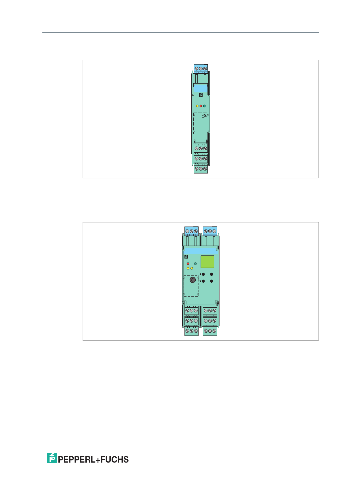
KC Device Housing
3
KCD2-SREx1.LB
PWR
OUT/CHK
1
2
S
3
4
241
I
II
Figure 2.3 KC device housing (12.5 mm)
Used for high signal integrity
• Compact 12.5 mm housing
• High packing density with single loop integrity
675
8
9
10
2021-03
8
Page 9
K-System – Isolated Barriers
Product Specifications
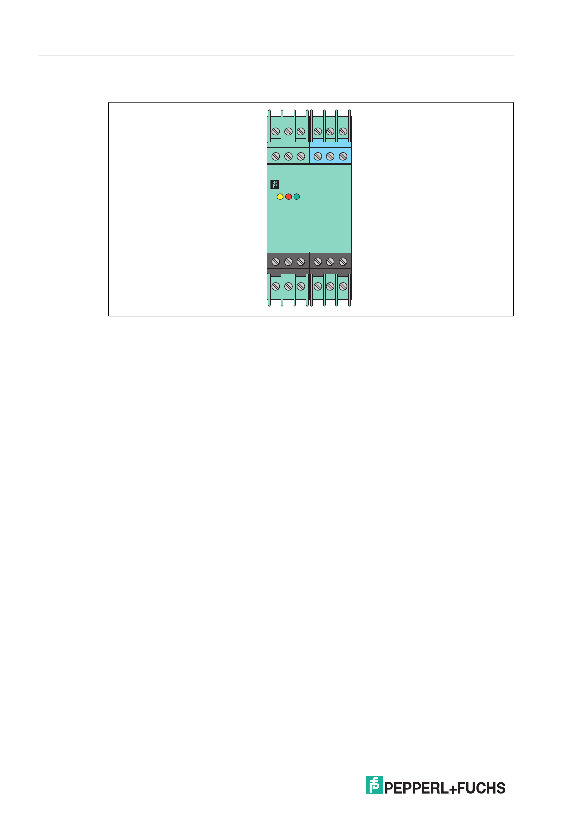
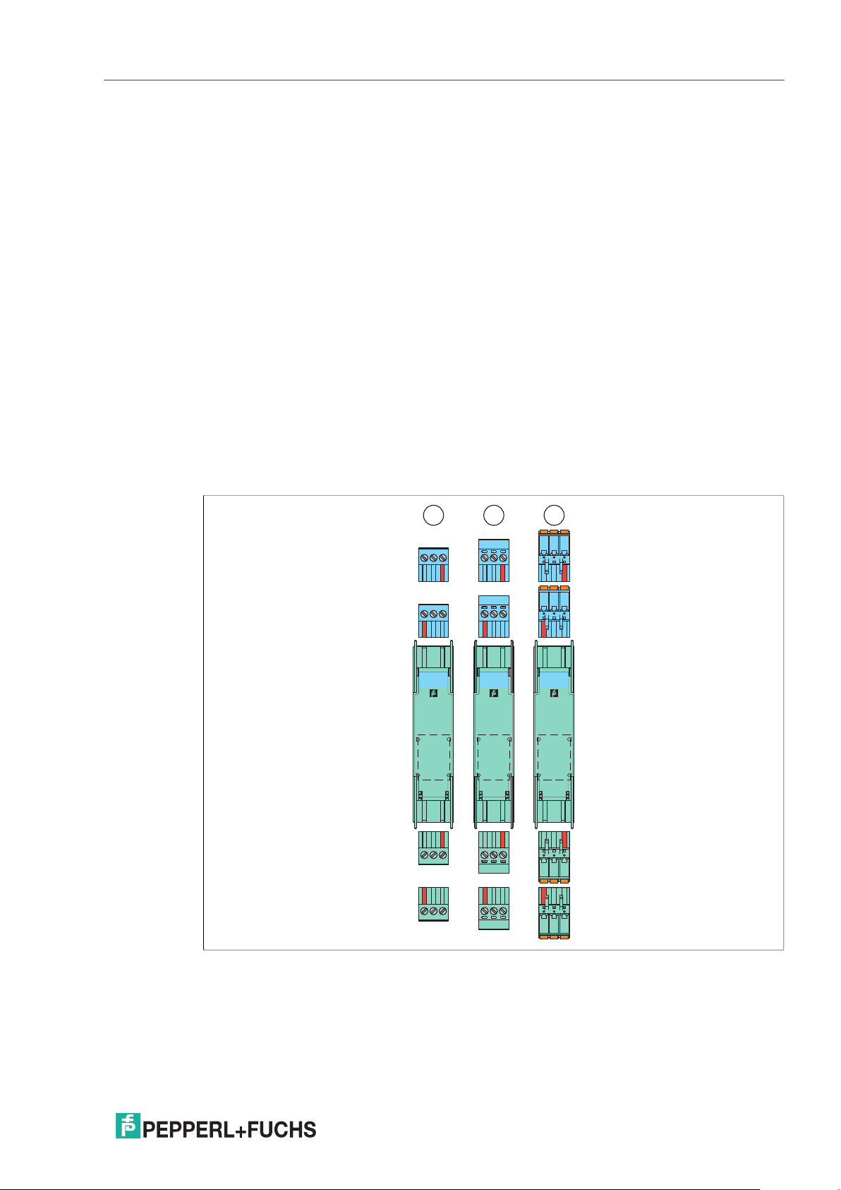
KF Device Housing
3
1
2
5
6
4
KFD2-ER-Ex1.W.LB
OUT CHK PWR
sens.
9107
8
12
11
13 15
14
Figure 2.4 KF device housing (20 mm)
Used for high channel density
• Compact 20 mm housing
• Packing density from 5 mm per channel
132465
KFD2-WAC2Ex1.D
PWR
FLT
12
OUT
11
17
22 24
23
ESC
OK
121610
18
RS232
8
14
19 21
20
9137
15
Figure 2.5 KF device housing (40 mm)
Used for applications with high functionality
• Digital devices monitor speed, direction of rotation, slip, flow rates and time.
• Analog devices monitor transmitter signals, temperature signals and load cells.
TM
• Configured using keypad or PACTware
software, see also manual "Installation
and Configuration Device Type Manager (DTM)"
• AC/DC wide range supply available
2021-03
9
Page 10
K-System – Isolated Barriers
Product Specifications
KH Device Housing
Figure 2.6 KH device housing (40 mm)
123
789
KHA6-SHEx1
1
CHKPWROUT
13 14 15
19 20 21
456
10 11 12
S
16 17 18
22 23 24
10
2021-03
Page 11
K-System – Isolated Barriers
12
9
10
7118
1
3
4
6
2
5
12
9
10
7118
1
3
4
6
2
5
12
9
10
7118
1
3
4
6
2
5
1 2 3
Product Specifications
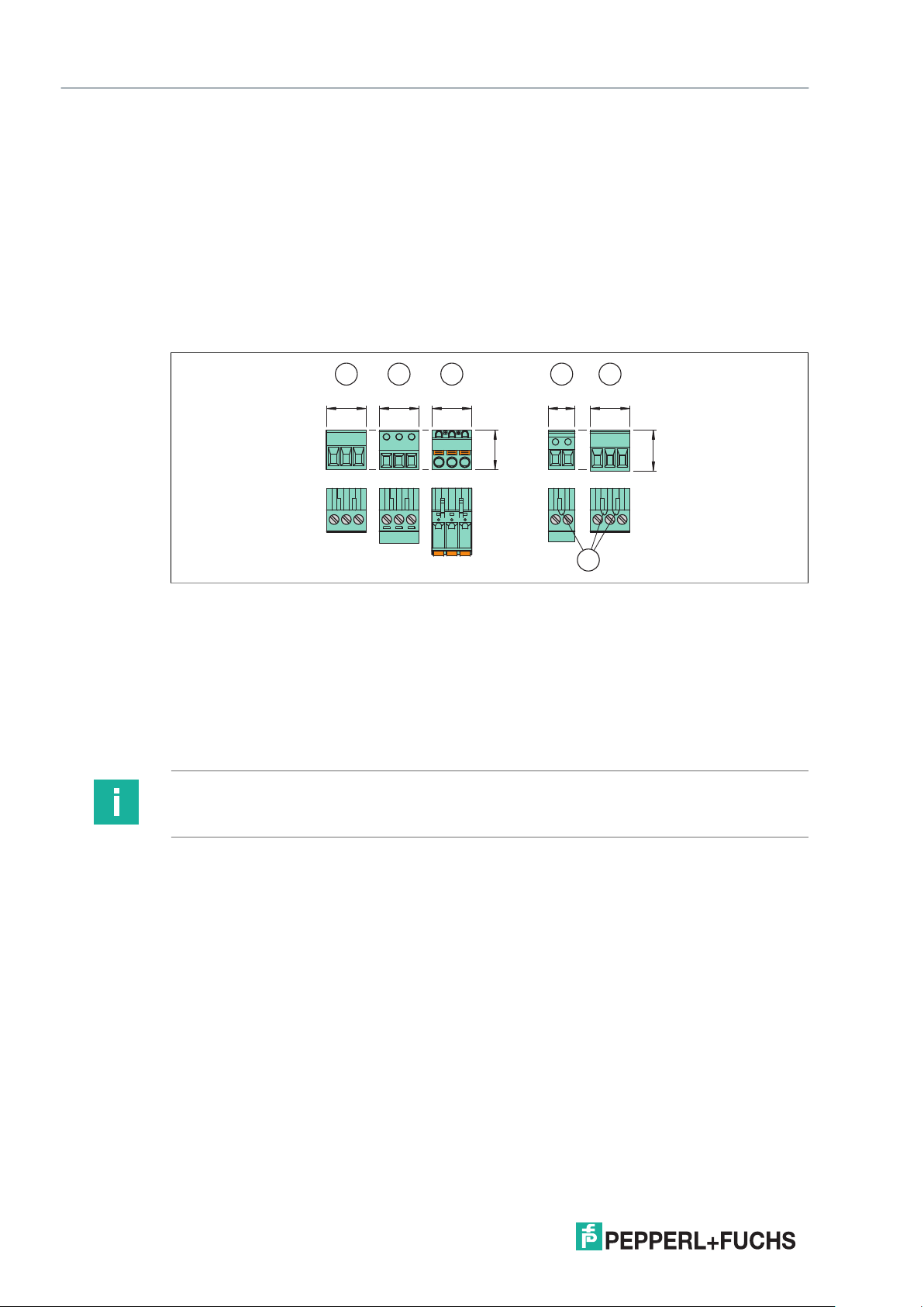
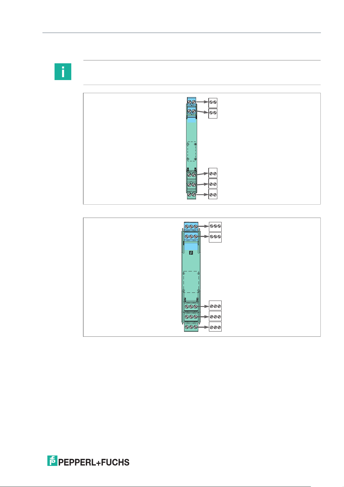
2.3 Terminals
2.3.1 Removable Terminal Blocks
The removable terminal blocks simplify connection and control cabinet assembly.
The terminal blocks offer space for the connection of leads with core cross-sections
of up to 2.5 mm
so misconnection of terminal blocks are eliminated.
Observe the tightening torque of the terminal screws. The tightening torque
is 0.5 Nm to 0.6 Nm.
The 20 mm and 40 mm wide KF devices are factory-equipped with screw terminals.
The KC devices are available with screw terminals or spring terminals. The order designation
of the versions of the KC devices with spring terminals has the extension ".SP".
As an alternative to the factory-equipped terminal blocks the devices can be used
with other terminal blocks:
• Terminal blocks with screw terminals
• Terminal blocks with screw terminals and test plug socket
• Terminal blocks with spring terminals and test plug socket
These terminal blocks are available as accessories. The terminal blocks can be easily coded
with KF-CP coding pins (available optionally).
2
(14 AWG). The terminal blocks are coded with red coding pins
2021-03
Figure 2.7 K-System removable terminal blocks
1 Terminal blocks with screw terminals
2 Terminal blocks with screw terminals and test sockets
3 Terminal blocks with spring terminals and test sockets
11
Page 12
K-System – Isolated Barriers
Product Specifications
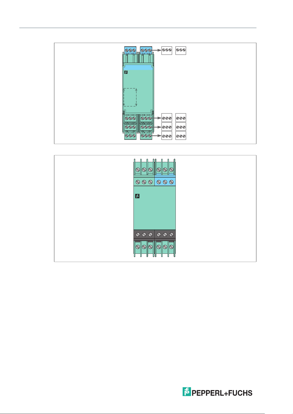
Protection against direct contact
The removable terminal blocks have different heights:
• Height 15 mm (1), (2), (3): These terminal blocks are used in applications that have rated
voltages lower than 50 V AC. The insulation of the removable terminal blocks provides
protection against direct contact. The insulation corresponds to a reinforced insulation
according to EN 61010-1 for a rated insulation voltage of 50 V AC.
• Height 15.5 mm (4), (5): These terminal blocks are used in applications that have rated
voltages higher than 50 V AC. The insulation of the removable terminal blocks provides
protection against direct contact. The insulation corresponds to a basic insulation
according to EN 61010-1 for a rated insulation voltage of 300 V AC. The higher terminals
are marked (X).
1 52 3 4
15.115.115.1
15
Figure 2.8 Removable terminal blocks with different heights
15.110.1
15.5
X
1 Terminal block with screw terminals, height 15 mm
2 Terminal block with screw terminals and test sockets, height 15 mm
3 Terminal block with spring terminals and test sockets, height 15 mm
4 Terminal block with screw terminals and test sockets, height 15.5 mm
5 Terminal block with screw terminals, height 15.5 mm
X Marking
Note
See corresponding datasheets for further information.
12
2021-03
Page 13
K-System – Isolated Barriers
9
10
8
675
241
3
3 4
1 2
7 8
5 6
9 10
1
3
4
6
2
5
13 15
12
9107
14
11
8
4 5 6
1 2 3
7 8 9
10 11 12
13 14 15
Product Specifications
2.3.2 Terminal Designation
Note
See corresponding datasheets for precise terminal designation.
Figure 2.9 KC device housing (12.5 mm)
Figure 2.10 KF device housing (20 mm)
2021-03
13
Page 14
K-System – Isolated Barriers
Product Specifications
Figure 2.11 KF device housing (40 mm)
132465
9137
8
15
14
19 21
20
11
17
22 24
23
1 2 3
4 5 6
121610
18
7 8 9
10 11 12
13 14 15
16 17 18
19 20 21
22 23 24
Figure 2.12 KH device housing (40 mm)
123
789
13 14 15
19 20 21
456
10 11 12
16 17 18
22 23 24
14
2021-03
Page 15
K-System – Isolated Barriers
ESC
OK
KFU8-UFTEx2.D
RS232
PWR1
12
3
2
4
IN/
CHK
OUT
19 21
15
9137
20
14
8
22 24
18
121610
23
17
11
132465
KFD2-ER-Ex1.W.LB
1
3
4
6
2
5
13 15
12
9107
14
11
8
OUT CHK PWR
sens.
KFA5-ER-Ex1.W.LB
1
3
4
6
2
5
13 15
12
9107
14
11
8
OUT CHK PWR
sens.
21 3
4
Product Specifications
2.4 Color Identification
The color identification of the devices has the following meaning:
• Green (1) indicates devices with DC power supply.
• Black (2) indicates devices with AC power supply.
• Gray (3) indicates devices with AC/DC wide range supply.
• Blue (4) indicates devices that process signals from the hazardous area.
Figure 2.13 Color identification of devices
1 green
2 black
3 gray
4 blue
2021-03
15
Page 16
K-System – Isolated Barriers
OUT CHK PWR
1 2 3
Product Specifications
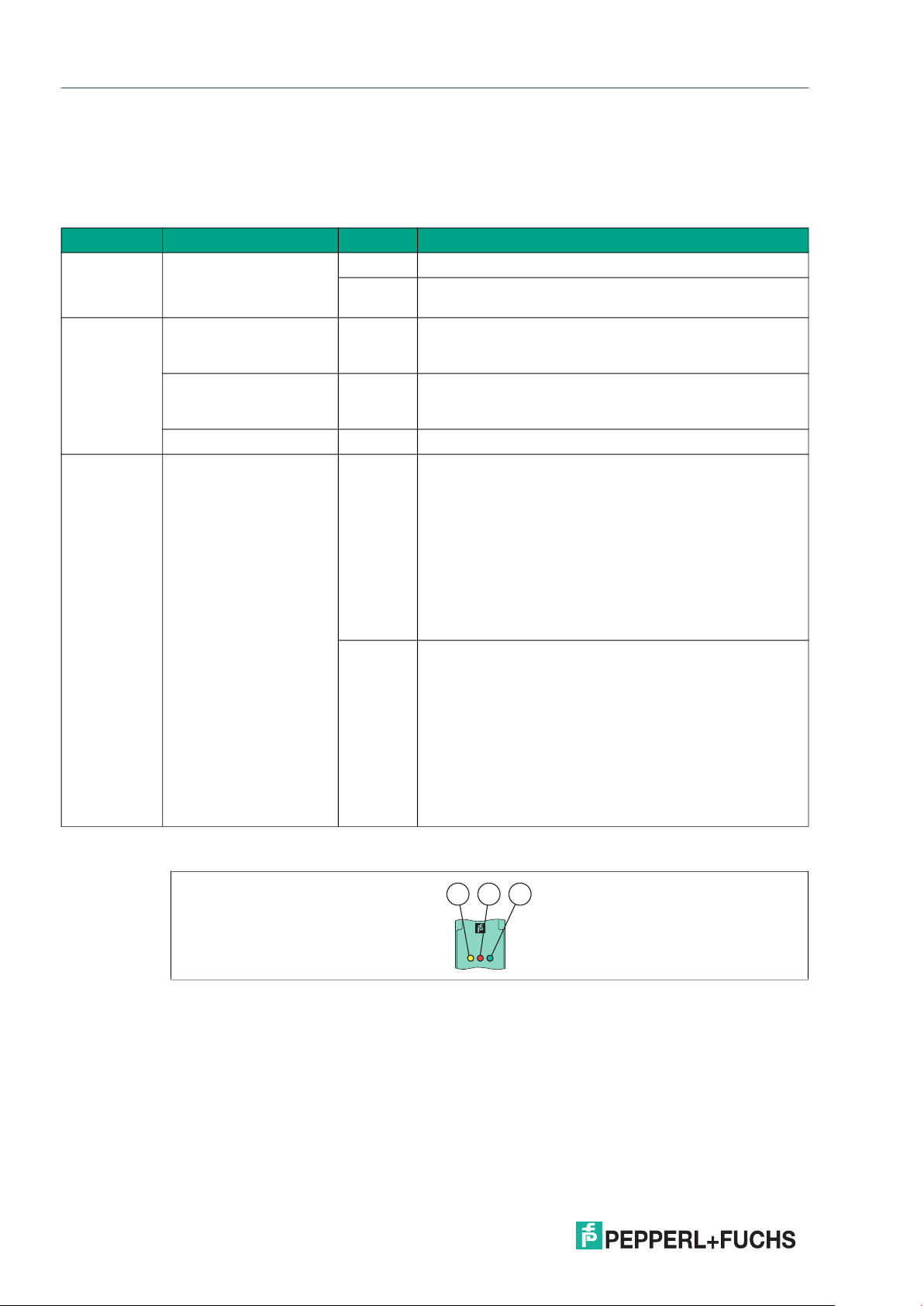
2.5 Status Indicators of the Isolators
LEDs are often used on isolators to indicate different statuses (e. g. for power supply,
device failure, status messages, binary switching states). Standard LED colors are assigned
to the status display according to NAMUR NE44.
LED Display function Display Meaning
Green LED Power supply On Power supply OK
Off No power supply or insufficient power supply – device
faulty
Red LED Device fault, device
failure
Line fault Flashing External fault signal, failure signal – fault/failure display
No fault Off No malfunction, device is operating properly
Yellow LED Switching states of
binary inputs and
outputs
On Internal fault signal, failure signal – fault/failure display
of causes detected inside the device, device needs
replacing
of causes detected outside the device, inspection
and elimination of fault required
On Possible causes of the output:
• The relay is energized.
• The NO contact (also a change-over contact)
is actively closed.
• The open collector is switched through.
• The switching voltage generated inside the device
is applied.
Possible causes of the input:
• A binary switching signal is present.
• An analog limit value is reached.
Off Possible causes of the output:
• The relay is de-energized.
• The NO contact (also a change-over contact)
is actively opened.
• The open collector is not switched through.
• The switching voltage generated inside the device
is not applied.
Possible causes of the input:
• A binary switching signal is present.
• An analog limit value is reached.
Table 2.1 Meaning of status indicators
16
Figure 2.14 Example status indicators
1 Yellow LED "OUT"
Switching state of the output
2 Red LED "CHK"
Lead breakage and short circuit status indicator
3 Green LED "PWR"
Power supply status indicator
2021-03
Page 17

K-System – Isolated Barriers
S2
S1
S3
III
1
SPAN
ZERO
1
Product Specifications
2.6 Operating Elements
Many devices of the K-System can be adapted to different applications.
Depending on the device different operating elements are available for this configuration.
These operating elements are:
DIP switches
Via DIP switches you can configure the basic functions of the device.
Figure 2.15
1 DIP switch
Rotary switches
Via rotary switches you can configure the basic functions of the device.
1
0
1
9
2
8
3
S2
7
4
6
5
Figure 2.16
1 Rotary switch
Potentiometers
Via potentiometers you can configure the calibration of input and output characteristics.
Figure 2.17
1 Potentiometer
2021-03
17
Page 18

K-System – Isolated Barriers
PROGRAM
1
Product Specifications
Keypad and LC display
Via keypad you can configure the settings of the device parameters. Measured values,
fault signals and configuration settings are displayed on the LC display.
Figure 2.18
1 LC display
2 Keypad
21
ESC
OK
Programming sockets for the connection of a PC with parameterization
software PACTware
TM
Via parameterization software PACTwareTM you can configure the device easily.
The configuration data can be edited and saved. The parameterization software helps users
for maintenance, diagnostics and troubleshooting.
Figure 2.19
1 Programming socket
Note
See manual "HART Multiplexer System KFD*-HM*-16" for further information for
communication via software.
Note
See corresponding datasheets for further information.
2021-03
18
Page 19

K-System – Isolated Barriers
21 2 3 4
Product Specifications
2.7 Label Carrier
For individual labeling, the isolated barriers are equipped ex works with a label carrier.
Labels can be inserted into the label carrier.
It is also possible to attach an adhesive label to the transparent front flap.
Figure 2.20 Devices with transparent front flap
1 Label carrier on KC devices with label 22 mm x 9 mm
2 Label carrier on KF devices for with 22 mm x 16.5 mm
3 Adhesive label 22 mm x 11 mm for all KC and KF devices, can only be used on devices
with a transparent front flap
4 Label carrier on KF devices with label 18 mm x 8 mm, can only be used on devices
without a transparent front flap
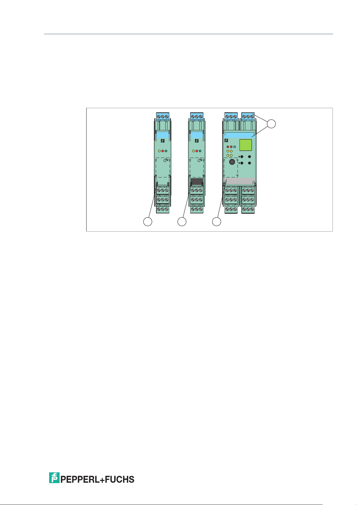
2.8 DIN Mounting Rail
The devices are mounted on a 35 mm DIN mounting rail according to EN 60715.
Figure 2.21 Example: DIN mounting rail UPR-MR (35 mm x 15 mm)
2021-03
19
Page 20

K-System – Isolated Barriers
1
2
34
Product Specifications
2.9 Power Rail
To reduce wiring and installation costs, Power Rail is the optimum solution. The Power Rail
is a DIN mounting rail with plastic insert, that delivers power to the devices (24 V DC)
and transfers bus signals and a collective error message.
The Power Rail is factory-equipped with cover and end caps. These parts cover empty
and open segments of the Power Rail. Thus, the Power Rail is protected from contamination.
Additionally the cover and end caps prevent that electrically conductive parts come in contact
with the Power Rail.
Power Rail is available in two versions:
Power Rail UPR-03
The Power Rail UPR–03 has 3 conductors.
• 2 conductors for power
• 1 conductor for collective error messaging
Power Rail UPR-05 (only for KFD2-WAC2-(Ex)1.D)
The Power Rail UPR–05 has 5 conductors.
• 2 conductors for power
• 1 conductor for collective error messaging
• 2 conductors for serial data exchange
Figure 2.22 Example: Power Rail UPR-03
1 Cover UPR-COVER
2 Insert UPR-INS-03
3 DIN mounting rail UPR-MR (35 mm x 15 mm)
4 End cap UPR-E
2021-03
20
Page 21

K-System – Isolated Barriers
Mounting and Installation
3 Mounting and Installation
Danger!
Explosion hazard from damaged electronic components
Premature wear of electronic components in a device that was previously used in a general
electrical installation can cause sparks that can ignite the surrounding potentially explosive
atmosphere.
Never install devices that have already been operated in general electrical installations
in electrical installations used in combination with hazardous areas!
Danger!
Explosion hazard from pollution
An excessively polluted surface of the device can become conductive and consequently ignite
a surrounding potentially explosive atmosphere.
Ensure that you install the device only in environments with a pollution degree 2 or better
according to IEC/EN 60664–1.
3.1 Mounting
Danger!
Danger to life from electric shock
Absent or insufficient insulation can result in electric shock.
Only connect supplies that provide protection against electric shock to power feed modules
(e. g. SELV or PELV).
Caution!
Property damage from use of isolators for Power Rail supply
Using the isolators for Power Rail supply can damage the isolators and make
the Power Rail fail.
Do not supply the Power Rail via isolators.
2021-03
21
Page 22

K-System – Isolated Barriers
Mounting and Installation
Mounting in the Non-Hazardous Area
Mounting the Isolated Barrier
Snap the device onto the DIN mounting rail in a vertical downward movement.
See following figure.
Mounting in Areas that Require the Equipment Protection Level Gc
Danger!
Explosion hazard from live wiring of non-intrinsically safe circuits
If you connect or disconnect energized non-intrinsically safe circuits in a potentially
explosive atmosphere, sparks can ignite the surrounding atmosphere.
Only connect or disconnect energized non-intrinsically safe circuits in the absence
of a potentially explosive atmosphere.
Danger!
Explosion hazard from wrong mounting
The device safety can be impaired by external environmental influences and
by mechanical stress. That can lead to sparking that can ignite a surrounding potentially
explosive atmosphere.
Mount the device in a surrounding enclosure that complies with IEC/EN 60079–0
and that is rated with the degree of protection IP54 according to IEC/EN 60529.
Mounting the Isolated Barrier
Snap the device onto the DIN mounting rail in a vertical downward movement.
See following figure.
CORRECT: Device snapped on vertically. INCORRECT: Device snapped on from the side.
Can damage the contacts and cause the device to fail.
Figure 3.1
2021-03
22
Page 23

K-System – Isolated Barriers
1
3
4
6
2
5
1
3
4
6
2
5
1
3
4
6
2
5
1
3
4
6
2
5
13
12
9
10
7
14 15
11
8
13
12
9
10
7
14 15
11
8
13
12
9
10
7
14 15
11
8
13
12
9
10
7
14 15
11
8
Mounting and Installation
Vertical and horizontal mounting
Low heat dissipation allows vertical or horizontal mounting without separation distance.
Operation is guaranteed over the full temperature range of the system in any mounting
direction and without restriction.
Figure 3.2 Vertical mounting without separation distance (group mounting)
3
1
2
5
4
8
11
13
14 15
3
3
1
1
2
11
14 15
2
5
5
6
4
9107
8
8
12
11
13
14 15
6
4
9107
12
13
3
1
2
5
6
6
4
9107
9107
8
12
12
11
13
14 15
Figure 3.3 Horizontal mounting without separation distance (group mounting)
2021-03
23
Page 24

K-System – Isolated Barriers
Mounting and Installation
Mounting Conditions for Operating the Device at Higher Ambient
Temperature
Certain devices with a maximum allowable ambient temperature of 60 °C (140 °F)
can be operated at ambient temperatures up to 70 °C (158 °F) if mounted horizontally.
These devices have a corresponding reference to this manual in the datasheet.
Caution!
Device failure due to overlooking heat dissipation
Overlooking heat dissipation can compromise the function and the electrical safety
of the device.
• Mount the device on the DIN mounting rail in a horizontal mounting position.
• Mount the device on the DIN mounting rail according to the specified minimum
separation distance.
• Do not operate devices without this reference in the datasheet at an ambient temperature
up to 70 °C (158 °F).
Mounting the Isolated Barriers with Separation Distance
Mount the device on the DIN mounting rail. Observe the specified minimum
separation distance.
See following figures.
• KC devices with 12.7 mm housing width, housing type A*: min. 6 mm
• KF devices with 20 mm housing width, housing type B*: min. 10 mm
• KF devices with 40 mm housing width, housing type C*: min. 15 mm
12.7 ≥6 12.7 ≥6
Figure 3.4 Horizontal mounting of KC devices with 12.7 mm housing width (single device mounting)
24
2021-03
Page 25

K-System – Isolated Barriers
40 ≥15 40 ≥15
Mounting and Installation
20 ≥10 20 ≥10
3
1
2
5
6
4
9107
8
12
11
13
14 15
3
1
2
5
6
4
9107
8
12
11
13
14 15
3
1
2
5
6
4
9107
8
12
11
13
14 15
Figure 3.5 Horizontal mounting of KF devices with 20 mm housing width (single device mounting)
Figure 3.6 Horizontal mounting of KF devices with 40 mm housing width (single device mounting)
2021-03
25
Page 26

K-System – Isolated Barriers
Mounting and Installation
Mounting the Terminal Blocks
Danger!
Danger to life from electric shock
Working on live parts at voltages higher than 50 V AC or 120 V DC can result
in electric shock.
Switch off the voltage.
1.
2. Connect the terminal blocks or disconnect the terminal blocks.
3.2 Connection
1. De-energize the device.
2. Secure the circuit against reconnection.
3. Verify that the device is de-energized at all poles.
4. Provide protection from adjacent live parts, if present.
Danger!
Explosion hazard from live wiring of non-intrinsically safe circuits
If you connect or disconnect energized non-intrinsically safe circuits in a potentially
explosive atmosphere, sparks can ignite the surrounding atmosphere.
Only connect or disconnect energized non-intrinsically safe circuits in the absence
of a potentially explosive atmosphere.
Danger!
Danger to life from electric shock
Absent or insufficient insulation can result in electric shock.
• Maintain sufficient distance between the connection lines, terminals,
surrounding enclosure, and the environment.
• Insulate connection lines, terminals, and the surrounding enclosure
from the environment.
Danger!
Danger to life from incorrect installation
Incorrect installation of cables and connection lines can compromise the function
and the electrical safety of the device.
• Observe the permissible core cross section of the conductor.
• When using stranded conductors, crimp wire end ferrules on the conductor ends.
• Use only one conductor per terminal.
• When installing the conductors the insulation must reach up to the terminal.
• Observe the tightening torque of the terminal screws.
26
2021-03
Page 27

K-System – Isolated Barriers
Mounting and Installation
Danger!
Explosion hazard from exposed conductors
Exposed conductors of inadequately attached cables can cause sparks that can ignite
the surrounding potentially explosive atmosphere.
When installing the device ensure that the cables are adequately attached.
Caution!
Property damage from use of inappropriate tool
Using an inappropriate tool may damage the screw heads.
• Use a slot-head screwdriver with a size of 3.5 x 0.5.
• Observe the tightening torque of the terminal screws. The tightening torque
is 0.5 Nm to 0.6 Nm.
Note
See corresponding datasheets for further information.
3.2.1 Field Side Connection
Danger!
Explosion hazard from wrong separation distances
If you do not observe the minimum separation distance between 2 intrinsically safe circuits,
this can lead to added currents or voltages. This can result in a current/voltage flashover
generating sparks. The sparks can ignite the surrounding potentially explosive atmosphere.
Ensure that you observe all separation distances between 2 adjacent intrinsically safe circuits
according to IEC/EN 60079-14.
Danger!
Explosion hazard from wrong separation distances
If you do not observe the minimum separation distances between intrinsically safe circuits
of associated apparatus and non-intrinsically safe circuits, this can lead to added currents
or voltages. This can result in a current/voltage flashover generating sparks.
The sparks can ignite the surrounding potentially explosive atmosphere.
Ensure that you observe the compliance of the separation distances to all non–intrinsically
safe circuits according to IEC/EN 60079–14.
Connecting the Field Side
Connect the field devices via the screw terminals or spring terminals.
2021-03
27
Page 28

K-System – Isolated Barriers
Mounting and Installation
3.2.2 Control Side Connection
Connection of Devices with Relay Output
Danger!
Danger to life from electric shock
Working on live parts at voltages higher than 50 V AC or 120 V DC can result in electric shock.
1. De-energize the device.
2. Secure the circuit against reconnection.
3. Verify that the device is de-energized at all poles.
4. Provide protection from adjacent live parts, if present.
Warning!
Risk of short circuit
Live working can cause injuries to the operator and/or damage to the device.
Disconnect the device, before you plug or unplug the plugs.
Connection of other Devices
Danger!
Danger to life from electric shock
Absent or insufficient insulation can result in electric shock.
Only connect circuits that provide protection against electric shock (e. g. SELV or PELV).
Warning!
Risk of short circuit
Live working can cause injuries to the operator and/or damage to the device.
Disconnect the device, before you plug or unplug the plugs.
Connecting the Control Side
Connect the control system via the screw terminals or spring terminals.
28
2021-03
Page 29

K-System – Isolated Barriers
Mounting and Installation
3.2.3 Power Supply Connection
The devices are available with different supply voltages.
• 24 V DC power supply
• 115 V AC or 230 V AC power supply for applications where direct current is not available
• AC/DC wide range supply with 24 V DC or 115/230 V AC
Note
The supported supply voltage for each device is identified on the side plate.
The devices are supplied with power in various ways.
• Power supply without Power Rail, see chapter 3.2.3.1
• Power supply with Power Rail, see chapter 3.2.3.2
• Non-redundant supply with power feed module
• Redundant supply with power feed module
• Direct supply with power supply
3.2.3.1 Power Supply without Power Rail
If devices with AC or universal power supplies are used, the advantages of Power Rail
are not available.
Conventional power supplies create complicated and expensive wiring systems.
After all isolated barriers are connected, there is a significant amount of wiring and more wiring
must be added for extra functions such as line fault detection.
Connection of KCD and KFD Devices
Danger!
Danger to life from electric shock
Absent or insufficient insulation can result in electric shock.
Only connect supplies that provide protection against electric shock (e. g. SELV or PELV).
Connection of KFA, KFU, and KHA Devices
Danger!
Danger to life from electric shock
Working on live parts at voltages higher than 50 V AC or 120 V DC can result in electric shock.
1. De-energize the device.
2. Secure the circuit against reconnection.
3. Verify that the device is de-energized at all poles.
4. Provide protection from adjacent live parts, if present.
Connecting the Power Supply
Connect the power supply via the screw terminals or spring terminals.
2021-03
29
Page 30

K-System – Isolated Barriers
1
3
4
6
2
5
1
3
4
6
2
5
1
3
4
6
2
5
1
3
4
6
2
5
13
12
9107
14 15
11
8
13
12
9107
14 15
11
8
13
12
9107
14 15
11
8
13
12
9107
14 15
11
8
1
24 V DC
Mounting and Installation
Figure 3.7 Conventional installation
1 DIN mounting rail
3.2.3.2 Power Supply with Power Rail
For devices with a 24 V DC supply voltage, use of the Power Rail reduces wiring and
installation costs. The Power Rail almost completely eliminates the risk of wiring faults
and facilitates expansion.
Power is supplied to the Power Rail via a power feed module which provides a voltage
of 24 V DC (max. 4 A) to a maximum of 80 devices.
The power feed module features a replaceable 5 A fuse at the front. This fuse ensures
that the Power Rail and connecting contacts are protected. It prevents damage caused
by reverse supply voltage or by installing too many isolators. The isolators on the Power Rail
feature integrated device fuses. Any faults in the isolator or in the signal leads do not affect
the Power Rail supply system. The 5 A fuse permits a rated current of up to 4 A across
the entire temperature range.
The power feed module also has the task of outputting a collective error message or power
failure of the isolators via a separate relay output.
Alternatively, supply of the Power Rail can be provided using the power supply
KFA6-STR-1.24.*. In this case, no collective error message is possible.
30
2021-03
Page 31

K-System – Isolated Barriers
1
3
4
6
2
5
1
3
4
6
2
5
1
3
4
6
2
5
1
3
4
6
2
5
13
12
9107
14 15
11
8
13
12
9107
14 15
11
8
13
12
9107
14 15
11
8
13
12
9107
14 15
11
8
1
3
4
6
2
5
13
12
9107
14 15
11
8
3
2
24 V DC
1
Mounting and Installation
Supply with Power Feed Module
Danger!
Danger to life from electric shock
Absent or insufficient insulation can result in electric shock.
Only connect supplies that provide protection against electric shock to power feed modules
(e. g. SELV or PELV).
Caution!
Property damage from use of isolators for Power Rail supply
Using the isolators for Power Rail supply can damage the isolators and make
the Power Rail fail.
Do not supply the Power Rail via isolators.
Connecting the Power Supply
Connect the power supply via the Power Rail.
Non-Redundant Supply
The power feed module mounts on the Power Rail for easy and reliable distribution of power
to all connected isolators. This method eliminates the wiring loops (daisy chain) necessary
on a conventional installation without Power Rail.
Figure 3.8 Power Rail installation
1 Replaceable fuse
2 Power feed module
3 Power Rail
2021-03
31
Page 32

K-System – Isolated Barriers
1
3
4
6
2
5
13
12
9107
14 15
11
8
1
3
4
6
2
5
13 15
12
9107
14
11
8
1
3
4
6
2
5
1
3
4
6
2
5
13
12
9107
14 15
11
8
13
12
9107
14 15
11
8
4
2 3
24 V DC 24 V DC
1
Mounting and Installation
Redundant Supply
Two power supplies or a redundant power supply with two power feed modules offer
a high degree of availability. If a power supply or the fuse in a power feed module fails,
the redundant supply continues to energize the isolators through their Power Rail connection.
Figure 3.9 Redundant power connections
1 Replaceable fuse
2 Power feed module 1
3 Power feed module 2
4 Power Rail
32
2021-03
Page 33

K-System – Isolated Barriers
1
3
4
6
2
5
1
3
4
6
2
5
13
12
9107
14 15
11
8
13
12
9107
14 15
11
8
21
115/230 V AC
24 V DC
1
3
4
6
2
5
1
3
4
6
2
5
13
12
9107
14 15
11
8
13
12
9107
14 15
11
8
PWR
1
3
4
6
2
5
13 15
12
9107
14
11
8
1
115/230 V AC
2
24 V DC
Mounting and Installation
Direct Supply with Power Supply
A complete power solution for a K-System installation is possible by using the following
power supplies:
• KFA6-STR-1.24.4 from 115/230 V AC to 24 V DC/4 A or
• KFA6-STR-1.24.500 from 115/230 V AC to 24 V DC/500 mA
The power supplies snap on the Power Rail to easily and efficiently distribute power
to the isolated barriers.
Figure 3.10 Integrated power supply (4 A)
1 Power supply
2 Power Rail
Figure 3.11 Integrated power supply (500 mA)
1 Power supply
2 Power Rail
2021-03
33
Page 34

K-System – Isolated Barriers
Mounting and Installation
3.2.4 Establishing the Communication via Software
Danger!
Explosion hazard from sparking when plugging or pulling the adapter
Plugging or pulling the adapter in a potentially explosive atmosphere can cause sparks
that can ignite the surrounding atmosphere.
Only plug or pull the adapter in the absence of a potentially explosive atmosphere.
Caution!
Fault in the plant
Changing the device data changes the device function.
Before entering new device data, make sure the plant is not endangered by changing
the device data.
Establishing the Communication via Software
Establish the HART communication via K-ADP-USB adapter and HART multiplexer
on the control side, if available.
Note
See manual "HART Multiplexer System KFD*-HM*-16" for further information
for communication via software.
34
2021-03
Page 35

K-System – Isolated Barriers
Configuration
4 Configuration
Danger!
Explosion hazard from sparking when using operating elements
Using operating elements in a potentially explosive atmosphere can cause sparks
that can ignite the surrounding atmosphere.
Only use operating elements (e. g., switch, slider, button, etc.) in the absence of a potentially
explosive atmosphere.
Caution!
Potential device malfunction from change of device function
Changes in the device function can lead to device malfunction. The function of the device
is no longer guaranteed.
Before transferring the new device function, make sure that the changed device function
does not cause a danger to the device and the plant.
Configuring the Device
Set the particular operating elements as described in section "Configuration" of the data sheet.
Note
See corresponding datasheets for further information.
2021-03
35
Page 36

K-System – Isolated Barriers
Operation
5 Operation
Danger!
Explosion hazard from live wiring of non-intrinsically safe circuits
If you connect or disconnect energized non-intrinsically safe circuits in a potentially
explosive atmosphere, sparks can ignite the surrounding atmosphere.
Only connect or disconnect energized non-intrinsically safe circuits in the absence
of a potentially explosive atmosphere.
Danger!
Explosion hazard from sparking when using operating elements
Using operating elements in a potentially explosive atmosphere can cause sparks that can
ignite the surrounding atmosphere.
Only use operating elements (e. g., switch, slider, button, etc.) in the absence of a potentially
explosive atmosphere.
5.1 Fault Monitoring
Numerous faults can occur between measurement of the process variable and evaluation
in the control system. This can lead to undesirable process statuses under certain
circumstances. These process statuses may result in plant downtime or quality problems
or even present a hazard to persons and the environment. Depending on the device version,
the isolators enable monitoring of the following faults:
• Line faults
Here, the connection cables between the isolator, the field device and the control system
are monitored for lead breakages or short circuits.
• Device faults
The isolators are designed so that internal faults are detected and reported.
In the case of a power failure, the outputs are switched to the de-energized state.
36
2021-03
Page 37

K-System – Isolated Barriers
2-
1+
7
8 (+/-)
FAU LT
10
11
12
2+
1+
7+
9-
FAU LT
Operation
5.2 Fault Output
Depending on the configuration of the devices, these faults are transmitted to the outputs
at the control side and in separate fault indication outputs as additional information.
• Red fault indication LEDs on the isolator
• Fault indication output
• Collective error message on Power Rail
Fault Indication Output
Line and device faults are transmitted if the device has a fault indication output (FAULT).
The fault indication output is active in a normal state and inactive in a fault state (closed-circuit
principle). Is it impossible to reverse the detection direction of the fault indication output.
Figure 5.1
Line Fault Transparency (LFT)
Line fault transparency makes electrical conditions on the field side visible on the control side
of the isolator. This enables line faults between the isolator and the field device to be detected
and transmitted to the control system via the signal line.
Figure 5.2 Example of line fault transparency with digital input
2021-03
37
Page 38

K-System – Isolated Barriers
Operation
Collective Error Message on Power Rail
The fault can also be output via the Power Rail as a collective error message (FAULT).
24 V DC
Power Rail
24 V DCFAULT
Figure 5.3
The collective error message enables line fault detection of many isolators without requiring
additional wiring. In the event of a fault, a fault message signal is transmitted to the Power Rail
from an isolator. The power feed module evaluates the signal and transmits the fault message
signal to the controller by means of a potential-free contact.
The potential-free contact simultaneously reports the device power failure or the failure
of one device minimum.
1
1
4
11
13 15
14
3
2
5
6
9107
8
12
3
3
1
1
2
2
5
5
6
4
4
9107
8
8
12
11
14 15
11
13
14 15
13
3
1
1
2
2
5
8
11
14 15
5
6
4
9107
8
12
11
13
14 15
6
4
9107
12
13
2
3
6
9107
12
4
24 V DC
3
Figure 5.4 Collective error message via power feed module
1 Power feed module
2 Fault indication on one of the devices (red LED flashes)
3 Process control system
4 Fault indication output
2021-03
38
Page 39

K-System – Isolated Barriers
I [mA]
42021
0 %
100 %
20.53.6 3.8
1 12
Operation
5.3 Current and Voltage Standard Signals
The following signals have established themselves as the standard:
• the 0/4 mA to 20 mA current signal
• the 0/2 V to 10 V voltage signal
• the 0/1 V to 5 V voltage signal
Analog sensor signals and digital frequency signals are converted into one of the two standard
signals for processing in a wide variety of measurement, regulatory and control tasks.
This offers the measurement and control technician an easy-to-measure standard signal
common to all manufacturers. Sensor signals are converted into standard signals via signal
converters.
For more diagnostic options, the NAMUR organization published NAMUR recommendation
NE43, dividing the value range of the signal (e. g. current signal) into several areas.
Valid, defined measurement value information is transferred within the range
from 3.8 mA to 20.5 mA. Failure information is available when the signal current is < 3.6 mA
or > 21 mA i. e. outside of the range for measured value information. The same applies
to the voltage signal.
Figure 5.5 Signal ranges according to NAMUR NE43 (e. g. current signal)
1 Failure information
2 Measuring information
2021-03
39
Page 40

K-System – Isolated Barriers
Dismounting, Maintenance, and Repair
6 Dismounting, Maintenance, and Repair
Danger!
Explosion hazard from live wiring of non-intrinsically safe circuits
If you connect or disconnect energized non-intrinsically safe circuits in a potentially
explosive atmosphere, sparks can ignite the surrounding atmosphere.
Only connect or disconnect energized non-intrinsically safe circuits in the absence
of a potentially explosive atmosphere.
Danger!
Danger to life from using damaged or repaired devices.
Using a defective or repaired device can compromise its function and its electrical safety.
• Do not use a damaged or polluted device.
• The device must not be repaired, changed or manipulated.
• If there is a defect, always replace the device with an original device from Pepperl+Fuchs.
Danger!
Danger to life from electric shock
Working on live parts at voltages higher than 50 V AC or 120 V DC can result in electric shock.
1. De-energize the device.
2. Secure the circuit against reconnection.
3. Verify that the device is de-energized at all poles.
4. Provide protection from adjacent live parts, if present.
Disconnecting Circuits
1.
Disconnect the power supply.
2. Disconnect the field circuit.
3. Disconnect the control circuit.
4. Disconnect the HART communication, if available.
40
2021-03
Page 41

K-System – Isolated Barriers
3 1
4
4
2
Dismounting, Maintenance, and Repair
6.1 Dismounting the Isolated Barrier
Dismounting the Isolated Barrier
Use for dismounting of the device a slotted screwdriver
1. Insert the screwdriver (4) into the groove of the red mounting slider (3).
2. Turn the screwdriver (4) in the groove until the red mounting slider (3) springs back.
3. Repeat these steps on the other side of the device.
4. Remove the isolator (2) from the DIN mounting rail (1).
Figure 6.1 Dismounting of the isolated barrier from the DIN mounting rail
1 35 mm DIN mounting rail
2 Isolated barrier
3 Mounting slider
4 Slotted screwdriver
2021-03
41
Page 42

K-System – Isolated Barriers
Technical Specifications
7 Technical Specifications
7.1 Technical Data
Electrical Data
Non-Hazardous Area Signals or Control Circuit Signals
• 0/4 mA to 20 mA signal level according to NE 43
• 0/2 V to 10 V signal level according to NE 43
• 0/1 V to 5 V signal level according to NE 43
• Current output HART compatible
• Current input HART compatible
• Digital output: active or passive electronic output 100 mA/30 V, short-circuit protected
• Relay output 2 A, minimum load 1 mA/24 V
• Logic level 24 V according to IEC 60946
• Functional isolation or safe isolation according to IEC 61140 and NAMUR NE 23
Hazardous Area Signals or Signals in the Field Circuit
• Transmitter power supply up to 17 V DC
• Current output HART compatible
• Pt100, 2-, 3-, (4)-wire technology
• Resistor 0 to 400 with freely definable characteristic
• Potentiometer
• Thermocouples of all types, internal cold junction, external reference
• Current output HART compatible
• Digital input according to NAMUR EN 60947-5-6
• Digital output for standard Ex-i valves, short-circuit protected
Characteristic Safety Values
• MTBF: Mean Time Between Failures
Conformity
General
• Isolators with and without explosion protection, mostly with Ex ia IIC/Class I Div. 1,
international approvals
• EMV according to
• EN 61326-1
• EN 61326-3-2, only for devices with SIL rating, where the data sheet mentions
this standard.
If you operate the device with a DC supply voltage, you must ensure that the bridging
of the 20 ms voltage interruption is realized by the power supply.
• NAMUR NE 21
If you operate the device with a DC supply voltage, you must ensure that the bridging
of the 20 ms voltage interruption is realized by the power supply.
42
2021-03
Page 43

K-System – Isolated Barriers
Technical Specifications
• LEDs according to NAMUR NE 44
• Software according to NAMUR NE 53
• Switch-on pulse suppression
• K*D2 devices:
• Supply voltage 20 V DC to 30 V DC via Power Rail or supply terminals
• Collective error message via Power Rail
• K*A devices:
• Supply voltage 115 V/230 V AC, details see datasheet
• K*U devices:
• Supply voltage 24 V DC or 115/230 V AC, details see datasheet
• Safety devices according to VDE 0660, part 209, AK according to DIN 19250
Digital Inputs and Outputs according to NAMUR
• IEC/EN 60947-5-6: Low voltage switch gear and control gear – part 5 and 6:
Control devices and switching elements – DC interface for proximity sensors
and switch amplifiers (NAMUR), 1999
Ambient Conditions
Ambient Temperature
• -20 °C to 60 °C (-4 °F to 140 °F), exceptions see data sheets
• extended ambient temperature range up to 70 °C (158 °F), necessary mounting
conditions see chapter 3.1
Storage Temperature
• -40 °C to 90 °C (-40 °F to 194 °F), exceptions see data sheets
Reference Conditions for Adjustment
• 20 °C (68 °F)
Relative Humidity
• max. 95 % without moisture condensation
Vibration Resistance
• according to EN 60068-2-6, 10 Hz to 150 Hz, 1 g, high crossover frequency
Shock Resistance
• according to EN 60068-2-27, 15 g, 11 ms, half-sine
Mechanical Specifications
Mounting
• Snap-on 35 mm DIN mounting rail according to EN 60715. Can be mounted horizontally
or vertically, side by side.
• Panel mount: The lugs on the base of the isolator must be extended and used
for mounting purposes with 3 mm screws.
• K-MS mounting base for screw attachment
Housing Material
• Polycarbonate (PC)
Dimensions
• Dimension drawings please refer to chapter Dimensions.
Protection Degree
• IP20 according to EN 60529
2021-03
43
Page 44

K-System – Isolated Barriers
Technical Specifications
Connection
• KH* devices: self-opening terminals for max. core diameter of 1 x 2.5 mm
• KF* and KC* devices: removable connector with integrated self opening terminals
for leads of up to a max. of 1 x 2.5 mm
• Observe the tightening torque of the terminal screws. The tightening torque
is 0.5 Nm to 0.6 Nm.
Fire Protection Class
• Housing: V2 according to UL 94 standard. Unless stated otherwise all details relate
to the reference conditions.
Labeling
Place for labeling on the front side:
• KC devices (12.5 mm): label 22 mm x 9 mm
• KF devices (20 mm and 40 mm): label 22 mm x 16.5 mm
• All KC and KF devices: adhesive label 22 mm x 11, can only be used on devices
with a transparent front flap
• KF devices: label 18 mm x 8 mm, can only be used on devices without a transparent front
flap
2
(14 AWG)
2
(14 AWG)
Note
See corresponding datasheets for further information.
44
2021-03
Page 45

K-System – Isolated Barriers
K - -Ex .
1 System
2 Construction type
3 Type of power supply
4 Level of power supply
9 Special function,
if available
8 Number of channels
7 Isolated Barriers,
not applicable to Signal Conditioners
6 Device generation (2 to X)
5 Device function
Technical Specifications
7.2 Model Number Description
Position 1 K K-System
Position 2 C Version with removable terminal blocks, 12.5 mm width
F Version with removable terminal blocks, 20 mm or 40 mm width
H Version without removable terminal blocks, 20 mm or 40 mm width
Position 3 D DC power supply
A AC power supply
U AC/DC power supply
Position 4 0 without power supply
2 24 V
4 100 V
5 115 V
6 230 V
8 24 V DC or 115/230 V AC
Position 5 CC Converter for current/voltage
2021-03
CD Active current driver
CR Transmitter power supply, current output
CRG Transmitter power supply with trip value
CS Passive current driver
DU Switch amplifier, time relay
DWB Overspeed/underspeed monitor, logic control unit
EB Power feed module
ELD Ground fault detection
ER Conductivity switch amplifier
FF RS 232 repeater
45
Page 46

K-System – Isolated Barriers
Technical Specifications
Position 5 GS Trip amplifier for current/voltage
GU Universal trip amplifier
GUT Temperature converter with trip value
HLC HART Loop Converter
HMM HART Multiplexer Master
HMS HART Multiplexer Slave
LGH Place holder isolator
PT Potentiometer converter
RC Converter for resistors
RCI Solenoid driver
RO Relay module
RR Thermometer resistance repeater
RSH Relay module in fail-safe technology
SCD SMART current driver
SCS SMART current driver/repeater
SD Solenoid driver, loop powered
SH Switch amplifier in fail-safe technology
SL Solenoid driver, bus powered
SLD Solenoid driver, bus and loop powered
SON Switch amplifier with NAMUR output
SOT Switch amplifier with passive, potential free transistor output
SR Switch amplifier with relay output
SRA Switch amplifier with relay output, 2:1 operation mode
SRT Switch amplifier with active transistor and relay output
ST Switch amplifier with active transistor output
STC SMART transmitter power supply with current output
STR Power supply
STV SMART transmitter power supply with voltage output
TR RTD converter
TT Converter for thermocouple/mV signal
UFC Universal frequency converter
UFT Frequency converter with direction and synchronization monitoring
USC Universal signal converter with trip value
UT Universal temperature converter
VC Converter for current/voltage
VCR Transmitter power supply, repeater for current/voltage
VD Solenoid driver
VM Solenoid driver
VR Voltage repeater
WAC Strain gauge converter
46
2021-03
Page 47

K-System – Isolated Barriers
12,7 mm
(0.5")
114 mm (4.49'')
46 mm (1.82'')58 mm (2.28'')
119 mm (4.7'')
104 mm (4.1'')
20 mm
115 mm
==
107 mm
93 mm
Technical Specifications
7.3 Dimensions
7.3.1 Housing Types Isolated Barriers K-System
Housing Type A2
Figure 7.1
Number of terminal blocks max. 5
• Dimension drawing with screw terminals
• When using screw terminals with test sockets the device is 124 mm (4.9 in) in height.
• When using spring terminals the device is 131 mm (5.16 in) in height.
Housing Type B1
Figure 7.2
Number of terminal blocks maximum 4
• Dimension drawing with screw terminals
• When using screw terminals with test sockets the device is 115 mm (4.6 in) in height.
• When using spring terminals the device is 122 mm (4.8 in) in height.
2021-03
47
Page 48

K-System – Isolated Barriers
Technical Specifications
Housing Type B2
20 mm
115 mm
46 mm58 mm
104 mm
119 mm
Figure 7.3
Number of terminal blocks maximum 5
• Dimension drawing with screw terminals
• When using screw terminals with test sockets the device is 124 mm (4.9 in) in height.
• When using spring terminals the device is 131 mm (5.16 in) in height.
Housing Type C1
40 mm (1.6'')
115 mm (4.5'')
==
93 mm (3.66'')
107 mm (4.21'')
Figure 7.4
Number of terminal blocks max. 8
• Dimension drawing with screw terminals
• When using screw terminals with test sockets the device is 115 mm (4.6 in) in height.
• When using spring terminals the device is 122 mm (4.8 in) in height.
48
2021-03
Page 49

K-System – Isolated Barriers
40 mm (1.6 inch)
115 mm (4.5 inch)
46 mm (1.82 inch)58 mm (2.28 inch)
119 mm (4.7 inch)
104 mm (4.1 inch)
Technical Specifications
Housing Type C2
Figure 7.5
Number of terminal blocks max. 10
• Dimension drawing with screw terminals
• When using screw terminals with test sockets the device is 124 mm (4.9 inch) in height.
• When using spring terminals the device is 131 mm (5.16 inch) in height.
Housing Type D2
60 mm (2.36'')
115 mm (4.5'')
46 mm (1.82'')58 mm (2.28'')
119 mm (4.7'')
104 mm (4.1'')
Figure 7.6
Number of terminal blocks max. 15
• Dimension drawing with screw terminals
• When using screw terminals with test sockets the device is 124 mm (4.9 in) in height.
• When using spring terminals the device is 131 mm (5.16 in) in height.
2021-03
49
Page 50

K-System – Isolated Barriers
140 mm (5.51'')88 mm (3.46'')
99 mm (3.9'')
103,5 mm (4.07'')
PE L1 N
+-
Primarily Secondary
Technical Specifications
Housing Type E
40 mm (1.6'')
Figure 7.7
Housing Power Supply 4 A
115 mm (4.5'')
==
93 mm (3.66'')
Figure 7.8
2021-03
50
Page 51

K-System – Isolated Barriers
Notes
2021-03
51
Page 52

Pepperl+Fuchs Quality
Download our latest policy here:
www.pepperl-fuchs.com/quality
© Pepperl+Fuchs · Subject to modifications
www.pepperl-fuchs.com
Printed in Germany / DOCT-0187V
 Loading...