

Frequency Converter with Direction and Synchronization Monitor
KFU8-UFT-2.D.FA
Features
• 2-channel signal conditioner
• Universal usage at different power supplies
• Dry contact or NAMUR inputs
• Input frequency 1 mHz ... 1 kHz
• Current output 0/4 mA ... 20 mA
• Relay contact and transistor output
• Start-up override
• Configurable by PACTware or keypad
• Line fault detection (LFD)
Function
This signal conditioner analyzes 2 digital signals (NAMUR
sensor/mechanical contact) and functions as a rotation
direction indicator, slip monitor, frequency monitor or
synchronization monitor.
Each proximity sensor or switch controls a passive transistor
output. The 2 relay outputs indicate if the input signal is above
or below the trip value or the rotational direction.
The analog output can be programmed to be proportional to
the input frequency or slip differential.
The unit is easily programmed by the use of a keypad located
on the front of the unit or with the PACTware™ configuration
software.
Line fault detection of the field current is indicated by a red
LED.
n, refer to the manual and
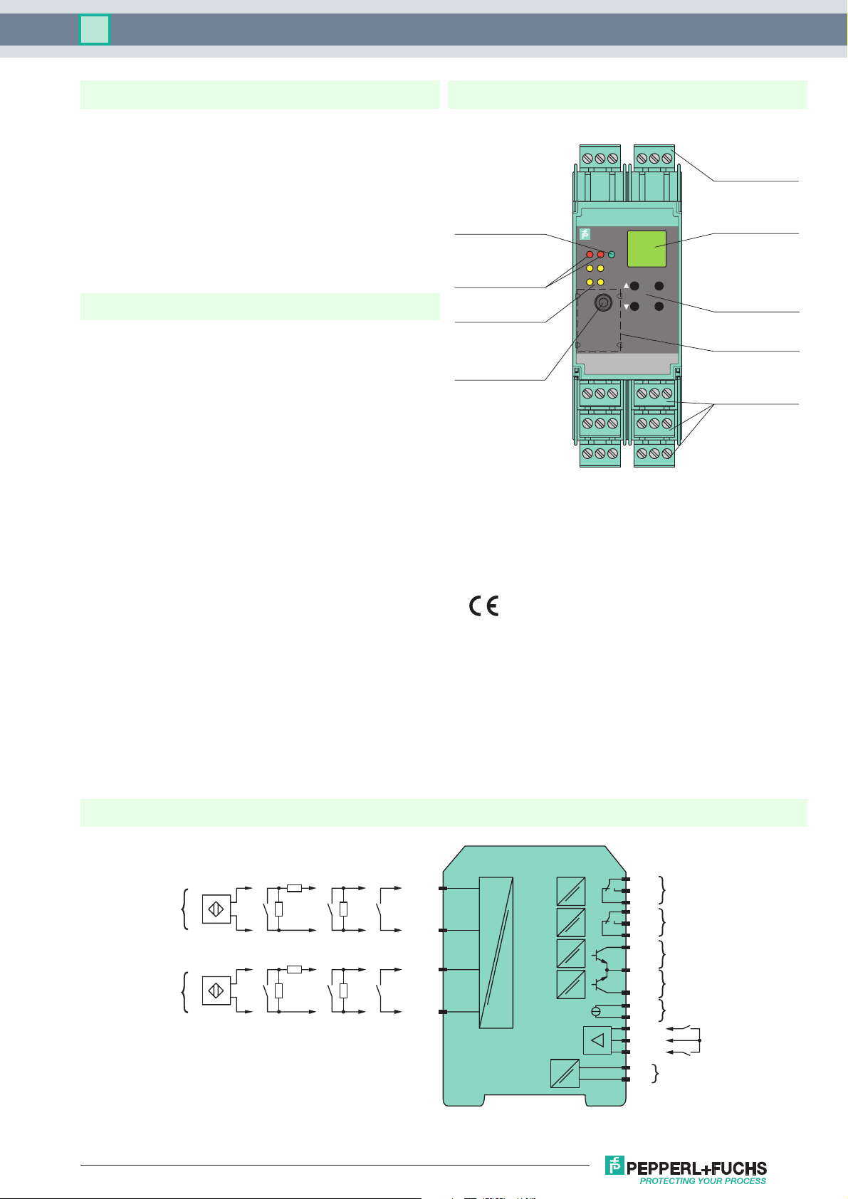
Assembly
Front v iew
LED green:
Power supply
LED yellow/red:
Input pulses/
fault signal
LED yellow:
Output I ... IV
Programming jack
1324
KFU8-UFT-
2.D.FA
PWR1
IN/
CHK
12
OUT
324
RS232
9137
8
15
14
19 21
20
22 24
Removable
terminals
green
6
5
LC display
ESC
OK
Keypad
Place for labeling
121610
11
18
17
23
Removable
terminals
green
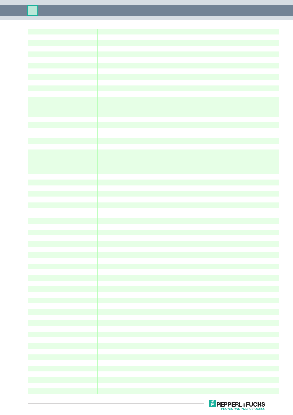
Connection
400 Ω ≤ R ≤ 2 kΩ
I
II
Release date 2018-05-08 08:06 Date of issue 2018-05-08 192334_eng.xml
Refer to "General Notes Relating to Pepperl+Fuchs Product Information".
USA: +1 330 486 0002 Germany: +49 621 776 2222
pa-info@us.pepperl-fuchs.com pa-info@de.pepperl-fuchs.com pa-info@sg.pepperl-fuchs.com
10 k Ω 10 k Ω
400 Ω ≤ R ≤ 2 kΩ
10 k Ω 10 k Ω
1+
3-
4+
6-
KFU8-UFT-2.D.FA
mA
10
11
12
16
17
18
19+
20-
21+
7-
8+
13+
1415+
23
24
I
II
III
IV
V
AC/DC
1
Technical data KFU8-UFT-2.D.FA
General specifications
Signal type Digital Input
Supply
Connection terminals 23, 24
Rated voltage U
Rated current I
r
Power dissipation 2.2 W / 3.5 VA
Power consumption 2.5 W / 4 VA
Interface
Programming interface programming socket
Input
Connection side field side
Connection input I: terminals 1+, 3-
Input III, IV
Active/Passive I > 4 mA (for min. 100 ms) / I < 1.5 mA
Open circuit voltage/short-circuit
current
Output
Connection side control side
Connection output I: terminals 10, 11, 12
Output I, II signal, relay
Contact loading 250 V AC / 2 A / cos φ ≥ 0.7 ; 40 DC / 2 A
Mechanical life 5 x 10⁷ switching cycles
Energized/De-energized delay approx. 20 ms / approx. 20 ms
Output III and IV signal , electronic output, passive
Contact loading 40 V DC
Signal level 1-signal: (L+) -2.5 V (50 mA, short-circuit/overload proof)
Output V analog
Current range 0 ... 20 mA or 4 ... 20 mA
Open loop voltage max. 24 V DC
Load max. 650 Ω
Fault signal downscale I ≤ 3.6 mA, upscale I ≥ 21.5 mA (acc. NAMUR NE43)
Programming interface
Connection programming socket
Interface RS 232
Transfer characteristics
Input I and II
Measurement range 0.001 ... 1000 Hz
Resolution slip monitoring: 1% frequency measurement: 0,1% of measured value; but >0.001Hz
Accuracy slip monitoring: 1% frequency measurement: 0.5% of measured value; but >0.001Hz
Measuring time frequency measurement: < 100 ms
Influence of ambient temperature 0.003 %/K (30 ppm)
Output I, II
Response delay ≤ 200 ms
Output V
Resolution < 10 µA
Accuracy < 30 µA
Influence of ambient temperature 0.005 %/K (50 ppm)
Galvanic isolation
Input I, II/other circuits reinforced insulation according to IEC/EN 61010-1, rated insulation voltage 300 V
Input III, IV/power supply reinforced insulation according to IEC/EN 61010-1, rated insulation voltage 300 V
Output I, II/other circuits reinforced insulation according to IEC/EN 61010-1, rated insulation voltage 300 V
Mutual output I, II, III reinforced insulation according to IEC/EN 61010-1, rated insulation voltage 300 V
Mutual output I, II, IV reinforced insulation according to IEC/EN 61010-1, rated insulation voltage 300 V
Output III, IV/power supply reinforced insulation according to IEC/EN 61010-1, rated insulation voltage 300 V
Output III, IV/input III, IV basic insulation according to IEC/EN 61010-1, rated insulation voltage 50 V
Output III, IV/V basic insulation according to IEC/EN 61010-1, rated insulation voltage 50 V
Output V/power supply reinforced insulation according to IEC/EN 61010-1, rated insulation voltage 300 V
Release date 2018-05-08 08:06 Date of issue 2018-05-08 192334_eng.xml
Refer to "General Notes Relating to Pepperl+Fuchs Product Information".
USA: +1 330 486 0002 Germany: +49 621 776 2222
pa-info@us.pepperl-fuchs.com pa-info@de.pepperl-fuchs.com pa-info@sg.pepperl-fuchs.com
20 ... 90 V DC / 48 ... 253 V AC 50 ... 60 Hz
r
approx. 130 mA
input II: terminals 4+, 6input III: terminals 13+, 14- (control input 1)
input IV: terminals 15+, 14- (control input 2)
18 V / 5 mA
output II: terminals 16, 17, 18
output III: terminals 19+, 20output IV: terminals 21+, 20output V: terminals 7-, 8+
0-signal: blocked output (off-state current ≤ 10 µA)
eff
eff
eff
eff
eff
eff
eff
eff
eff
2

Technical data KFU8-UFT-2.D.FA
Interface/power supply reinforced insulation according to IEC/EN 61010-1, rated insulation voltage 300 V
Interface/output III, IV basic insulation according to IEC/EN 61010-1, rated insulation voltage 50 V
eff
eff
Indicators/settings
Display elements LEDs , display
Control elements Control panel
Configuration via operating buttons
via PACTware
Labeling space for labeling at the front
Directive conformity
Electromagnetic compatibility
Directive 2014/30/EU EN 61326-1:2006
Low voltage
Directive 2014/35/EU EN 61010-1:2010
Conformity
Electromagnetic compatibility NE 21:2006
Degree of protection IEC 60529:2001
Input EN 60947-5-6:2000
Ambient conditions
Ambient temperature -20 ... 60 °C (-4 ... 140 °F)
Mechanical specifications
Degree of protection IP20
Connection screw terminals
Mass 300 g
Dimensions 40 x 119 x 115 mm (1.6 x 4.7 x 4.5 inch) , housing type C3
Mounting on 35 mm DIN mounting rail acc. to EN 60715:2001
General information
Supplementary information Observe the certificates, declarations of conformity, instruction manuals, and manuals where applicable. For
information see
Release date 2018-05-08 08:06 Date of issue 2018-05-08 192334_eng.xml
Refer to "General Notes Relating to Pepperl+Fuchs Product Information".
USA: +1 330 486 0002 Germany: +49 621 776 2222
pa-info@us.pepperl-fuchs.com pa-info@de.pepperl-fuchs.com pa-info@sg.pepperl-fuchs.com
3

Technical data KFU8-UFT-2.D.FA
Function
The device processes two input frequencies up to a max. of 1 kHz. The following functions are provided by the device:
• Frequency measurement with freely adjustable trip value monitoring for high and low alarm as well as for frequency-currentconversion (0/4 mA ... 20 mA)
• Slip monitoring: The slip is calculated from the two input frequencies at channel I and II. If the freely parameterisable trip value
is exceeded, the respective output switches.
• Rotation direction signalling: The rotation direction is evaluated from the two input signals with the same frequency and a
phase shift of 90°. The corresponding outputs switch according to the direction of rotation.
• The frequency monitoring can be used in combination with rotation direction signalling or slip monitoring.
• Synchronisation monitor: The synchronisation monitor compares the pulse counts of the two inputs. If the measured
difference in the pulses is greater than the programmed value the corresponding outputs are switching.
The two electronic outputs serve to repeat the input signals.
Maximum Switching Power of Output Contacts
I (A)
4
3
2
1
0.5
0.4
0.3
0.2
0.15
0.1
0 50 150 200 250100
Resistive load DC
Resistive load AC
1 max. 105 switching cycles
1
U (V)
Accessories
PACTware™
Device-specific drivers (DTM)
Adapter K-ADP1
Programming adapter for parameterisation via the serial RS 232 interface of a PC/Notebook
For programming, please use the new version of adapter K-ADP1 (part no. 181953, connector length 14mm). When using the
previous version K-ADP1 (connector length 18 mm) the plug is exposed by approx. 3 mm. The function is not affected.
Adapter K-ADP-USB
Programming adapter for parameterisation via the serial USB interface of a PC/Notebook
Release date 2018-05-08 08:06 Date of issue 2018-05-08 192334_eng.xml
Refer to "General Notes Relating to Pepperl+Fuchs Product Information".
USA: +1 330 486 0002 Germany: +49 621 776 2222
pa-info@us.pepperl-fuchs.com pa-info@de.pepperl-fuchs.com pa-info@sg.pepperl-fuchs.com
4
 Loading...