

Pepperl Fuchs KFU8-GUT-1.D Datasheet
2
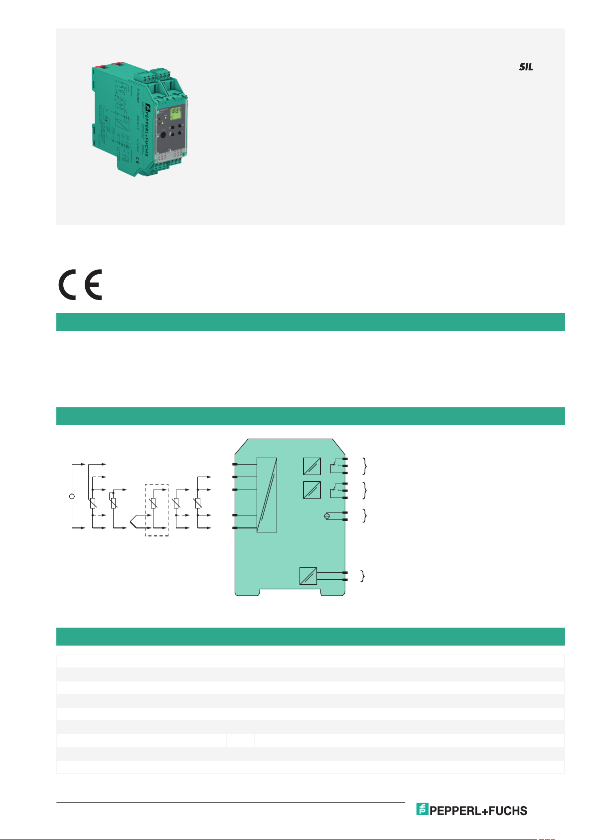
Function
KFU8-GUT-1.D
16
17
18
10
11
12
I
II
78+
III
4
3
6
2
1
T T
AC/DC
23
24
+
-
V
mA
+
-
T
K-CJC-**
Germany: +49 621 776 2222Pepperl+Fuchs Group
Refer to "General Notes Relating to Pepperl+Fuchs Product Information".
USA: +1 330 486 0002 Singapore: +65 6779 9091
www.pepperl-fuchs.com pa-info@us.pepperl-fuchs.com pa-info@sg.pepperl-fuchs.com
pa-info@de.pepperl-fuchs.com
Temperature Converter with Trip Values
KFU8-GUT-1.D
1-channel signal conditioner
<
Universal usage at different power supplies
<
Thermocouple, RTD, potentiometer or voltage input
<
Redundant TC input
<
Current output 0/4 mA ... 20 mA
<
2 relay contact outputs
<
Configurable by PACTware or keypad
<
Line fault (LFD) and sensor burnout detection
<
Up to SIL 2 acc. to IEC 61508/IEC 61511
<
This signal conditioner provides the galvanic isolation beetween field circuits and control circuits.
The device converts the signal of a resistance thermometer, thermocouple, potentiometer, or voltage source to a proportional output current. It
also provides a relay trip value.
The removable terminal block K-CJC-** is available as an accessory for internal cold junction compensation of thermocouples.
A fault is signalized by LEDs acc. to NAMUR NE44.
The device is easily configured by the use of the PACTware configuration software.
For additional information, refer to the manual and www.pepperl-fuchs.com.
Connection
Technical Data
General specifications
Signal type Analog input
Functional safety related parameters
Safety Integrity Level (SIL) SIL 2
Supply
Connection terminals 23, 24
Rated voltage U
Power dissipation/power consumption ≤ 2 W ; 2.5 VA / 2.2 W ; 3 VA
Interface
Release date: 2020-09-23 Date of issue: 2020-09-23 Filename: 231226_eng.pdf
r
20 ... 90 V DC / 48 ... 253 V AC
1

Temperature Converter with Trip Values KFU8-GUT-1.D
Germany: +49 621 776 2222Pepperl+Fuchs Group
Refer to "General Notes Relating to Pepperl+Fuchs Product Information".
USA: +1 330 486 0002 Singapore: +65 6779 9091
www.pepperl-fuchs.com pa-info@us.pepperl-fuchs.com pa-info@sg.pepperl-fuchs.com
pa-info@de.pepperl-fuchs.com
Technical Data
Programming interface programming socket
Input
Connection side field side
Connection terminals 1, 2, 3, 4, 6
RTD Pt100, Pt500, Pt1000, Ni100, Ni1000
Measuring current approx. 400 µA
Types of measuring 2-, 3-, 4-wire technology
Lead resistance max. 50 Ω
Measurement loop monitoring sensor breakage, sensor short-circuit
Thermocouples type B, E, J, K, L, N, R, S, T (IEC 584-1: 1995)
Cold junction compensation external and internal
Measurement loop monitoring sensor breakage
Potentiometer 0.8 ... 20 kΩ
Types of measuring 2-, 3-, 5-wire technology
Voltage 0 ... 10 V , 2 ... 10 V , 0 ... 1 V , -100 ... 100 mV
Open loop voltage max. 5 V with resistance measuring sensor
Input resistance ≥ 250 kΩ (0 ... 10 V)
Output
Connection side control side
Connection output I: terminals 10, 11, 12
Output I, II relay
Contact loading 250 V AC / 2 A / cos φ ≥ 0.7 ; 40 DC / 2 A
Mechanical life 5 x 10⁷ switching cycles
Energized/De-energized delay approx. 20 ms / approx. 20 ms
Output III Analog current output
Current range 0 ... 20 mA or 4 ... 20 mA
Open loop voltage max. 24 V DC
Load max. 650 Ω
Fault signal downscale I ≤ 3.6 mA, upscale I ≥ 21 mA (acc. NAMUR NE43)
Transfer characteristics
Deviation
Temperature effect Input: 0.005 %/K (50 ppm) of span ; current output: 0.005 %/K (50 ppm) of span
RTD max. 0.2 % of span
Thermocouples max. 10µV
Voltage 0.1 % of span
Potentiometer 0.1 % of span when < 5 kΩ
Current output max. 20 µA
Sampling rate approx. 700 ms
Galvanic isolation
Input/Other circuits reinforced insulation according to IEC/EN 61010-1, rated insulation voltage 300 V
Output I, II against eachother reinforced insulation according to IEC/EN 61010-1, rated insulation voltage 300 V
Output I, II/other circuits reinforced insulation according to IEC/EN 61010-1, rated insulation voltage 300 V
Output III/power supply reinforced insulation according to IEC/EN 61010-1, rated insulation voltage 300 V
Interface/power supply reinforced insulation according to IEC/EN 61010-1, rated insulation voltage 300 V
Indicators/settings
Display elements LEDs , display
Control elements Control panel
Configuration via operating buttons
Labeling space for labeling at the front
Release date: 2020-09-23 Date of issue: 2020-09-23 Filename: 231226_eng.pdf
min. 1 MΩ (0 ... 1 V, -100 ... 100 mV)
output II: terminals 16, 17, 18
output III: terminals 8+, 7-
deviation of CJC: ±0.8 K
0.5 % of span when > 5 kΩ
via PACTware
eff
eff
eff
eff
eff
2
 Loading...