

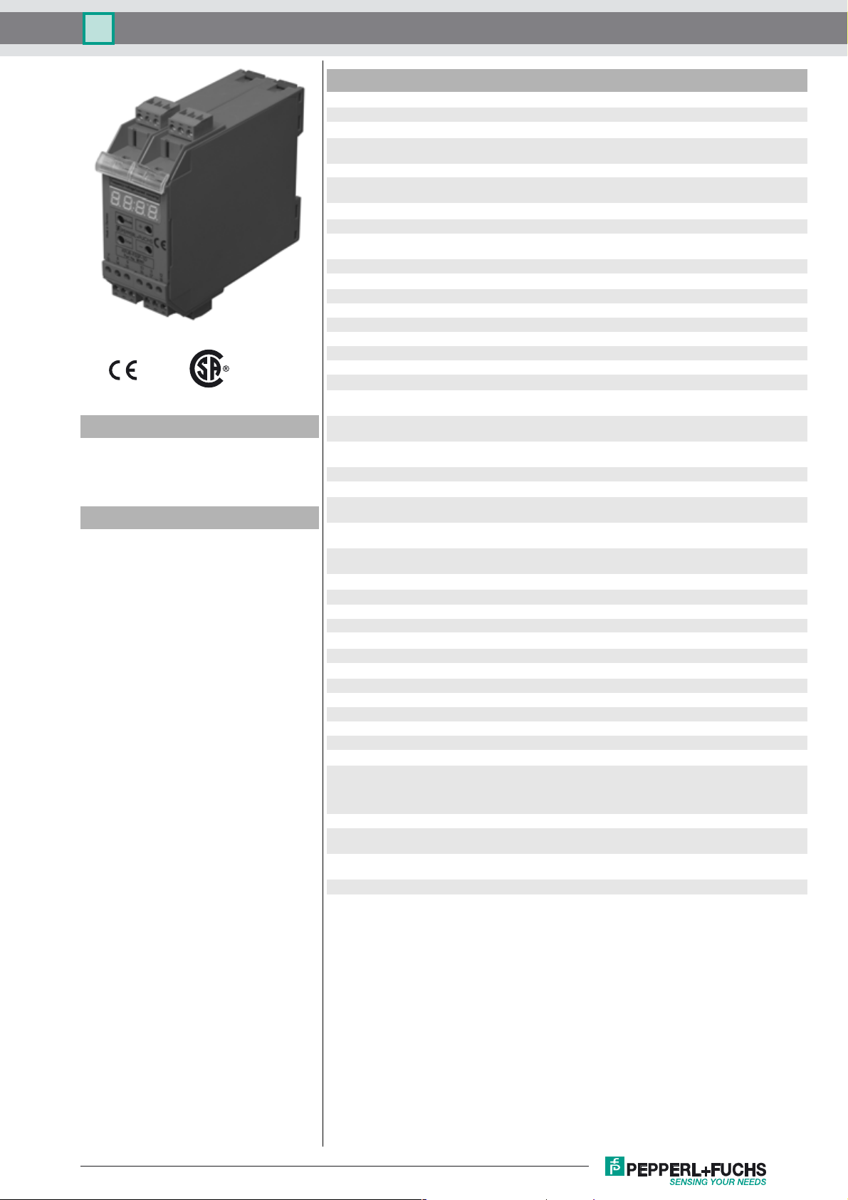
Frequency voltage current converter KFU8-FSSP-1.D
Technical data
Functional safety related parameters
MTTFd 100 a
Supply
Model Number
KFU8-FSSP-1.D
Frequency voltage current converter
40 kHz version
Features
• Limit frequency 40 kHz
• Voltage or current ouptput
• Incrementing output
(Spacing factor 1 ... 9999)
• Multi-range power pack
• 2-, 3-, 4-wire and NAMUR sensors as
well as rotary encoder connectable
• Auxiliary power output for sensors
• Connection via Power Rail
• Period measurement
• Display: Input in Hz or 1/min, output in
V or mA
• adjustable updating of indication
(0,001 ... 2,5 s)
Rated voltage Ur200 ... 230 V AC ; 100 … 130 V AC; 50 Hz
Fusing external fusing 4 A
Power consumption AC: < 5 VA
Indicators/operating means
Ty p e 4-digit, 7-segment red display, 7 mm digit height
Display interval 0.002 ... 9999 Hz or
Parameter assignment keypad-driven menu
Input 1
Connection terminals 8-, 9+
Connectable sensor types NAMUR sensors according to DIN EN 60947-5-6
Open loop voltage 8.2 V DC
Short-circuit current 6.5 mA
Switching point 1.2 ... 2.1 mA Switching hysteresis approx. 0.2 mA
nce 1.2
Impeda
Input 2
Switching point high: 16 ... 30 V DC; max.10 mA; Ri ≅ 3 kOhm
Connection terminals 7+, 13- sensor supply
Connectable sensor types 2-, 3-, or 4-wire proximity switches and incremental rotary enco-
Sensor supply 19 ... 28 V DC non-stabilised; ≤ 30 mA short-circuit protected
Output
Analog voltage output 0 ... 10 V DC; 2 ... 10 V DC; 30 mA max.; resolution: 12 mV; Ri ≥
Analog current output 0 ... 20 mA; 4 ... 20 mA; resolution: 25 µA; R
Digital incrementing ≥ (Ub -3 V), 20 mA, short-circuit proof (Terminals 1-, 2+)
Transfer characteristics
Input frequency ≤ 40000 Hz, pulse pause/pulse length: ≥ 12 µs
Deviation ≤ 0.2 % of full-scale value
Changing interval 5 ms (Internal processing time)
Standard c on fo rm ity
Electromagnetic compatibility acc. to EN 50081-2 / EN 50082-2
Ambient conditions
Ambient temperature -25 ... 40 °C (-13 ... 104 °F)
Storage temperature -40 ... 85 °C (-40 ... 185 °F)
Relative humidity max. 80 %, not condensing
Altitude 0 ... 2000 m
Operating conditions The device has only to be used in an indoor area.
Mechanical specifications
Connection assembly Caution: Please be aware that the device may only be connec-
Degree of protection IP20
Connection coded, removable terminals , max. core cross section 0.34 ... 2.5
Construction type modular terminal housing in Makrolon, System KF
Mounting snap-on to 35 mm standard rail or screw fixing
20 VDC ... 30 VDC
DC: < 5 W
0.01 ... 9999 min
kOhm
low: 0 ... 6 V DC
terminals 14, 15 NPN/PNP input (galvanically isolated)
der
330 Ω (terminal 5+, 6-)
, 5+)
with frequency division F
ted to a switchable power supply. The switch or circuit breaker
must be easy to reach and identified as the separator for the
device.
2
mm
For use in the switch cabinet/switch cabinet module
-1
/1 ... Fin /9999
in
≤ 600 Ω (terminal 4-
i
Release date: 2017-01-03 10:43 Date of issue: 2017-01-03 181191_eng.xml
Refer to “General Notes Relating to Pepperl+Fuchs Product Information”.
1
Dimensions
7-segment-display
Control keys
123 456
Drehzahlwächter
Output
Speed monitor
Mode
+
Enter
–
PEPPERL+FUCHS GERMANY
789 101112
13 14 15 16 17 18
KFU8-FSSP-1.DFrequency voltage current converter
11540
93
107
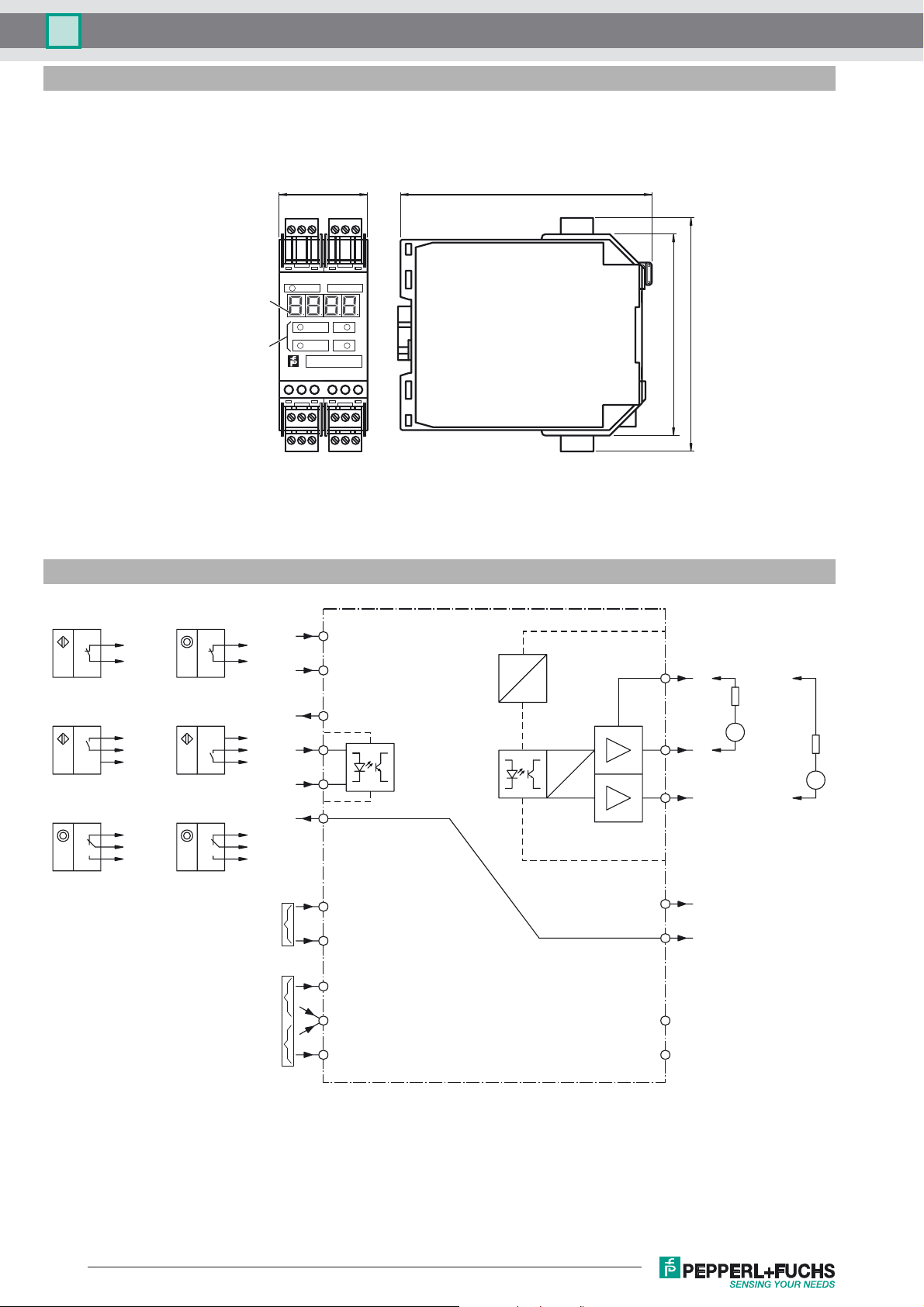
Electrical connection
NAMUR
Sensor
DC-3-wire
sensor, PNP
Encoder,
push-pull
L+
9
8
L–
L+
7
15
13, 14
L–
L+
7
15
13, 14
L–
NAMUR
Encoder
DC-3-wire
sensor, NPN
Encoder,
push-pull
Power supply 24 V DC
Power supply 230 V AC
Power supply 115 V AC
L+
9
8
L–
L+
7, 15
14
13
L–
L+
7, 15
9
NAMUR L+
8
NAMUR L–
7
Sensor power supply 24 V
15
14
13
Sensor power
supply GND
Galvanically
isolated input for
PNP- and NPNoutput circuits
DC
DC
5I+ / U+
Ri ≤ 600 Ω
I–U–4
mA
Ri ≥ 330 Ω
D
A
6
V
14
13
L–
11
L+
12
L–
Pulse output
Sensor power
supply GND
2
1
16
L1 (230 V)
18
17
N
L1 (115 V)
Not connected
Not connected
3
10
Refer to “General Notes Relating to Pepperl+Fuchs Product Information”.
2
Release date: 2017-01-03 10:43 Date of issue: 2017-01-03 181191_eng.xml

Frequency voltage current converter KFU8-FSSP-1.D
Function
The KFU8-FSSP-1.D frequency-voltage/current converter is a device for displaying and monitoring periodic signals, which occur in almost all
areas of the automation and processing industry, i.e. frequencies in general and rotational speeds in particular.
Input pulses are evaluated according to the cycle method, i.e. by measurement of the periodicity, and are converted into a frequency or rotational
speed by a µ controller. Depending on the measurement range value selected, the µ controller calculates a voltage or current value proportionate
to the input frequency and exports this value via a digital-analog converter.
The following analogue signals are available for selection: 0 V ... 10 V, 2 V... 10 V, 0 mA ... 20 mA, 4 mA ... 20 mA.
The serially switched output provides the input frequency which can be subdivided by the adjustable factor (1 ... 9999).
Special consideration was given to the frequently occurring special case of rotational speed measurement during the development of the device.
This makes it possible for the display and inputs to be either Hz or in min
In addition, in applications with signal encoders that return multiple pulses per revolution, it is possible to operate automatically at the actual
speed of the drive by assigning the number (1 ... 1200).
The frequency/voltage/current converter is supplied with 115 V AC, 230 VAC or 24 V DC. When it is connected with alternating voltage it provides an unstabilised 24-VDC source of power for the signal encoder.
All commonly available two- three- or four-wire proximity switches and incremental encoders on the input galvanically separated by an optical
coupler are accepted as a signal source. In addition, two terminals are reserved for connecting proximity switches or incremental encoders in
accordance with DIN 19234 (NAMUR).
The input signal frequency in Hz or the speed in min
display on the front of the device. Parameters can be set with 4 buttons underneath the display.
-1
- or the output signal voltage in V or current in mA - appears in a 4-place 7-segment LED
-1
.
Release date: 2017-01-03 10:43 Date of issue: 2017-01-03 181191_eng.xml
Refer to “General Notes Relating to Pepperl+Fuchs Product Information”.
3

Function description
Operating mode
MODE
+ +
MODE
KFU8-FSSP-1.DFrequency voltage current converter
+
+
–
–
+
+
ENTER
+ –
+ –
+ –
+ –
+ –
+ –
+ –
+ –
MODE
ENTER
MODE
ENTER
MODE
ENTER
MODE
ENTER
MODE
ENTER
MODE
ENTER
MODE
ENTER
ENTER
MODE
ENTER
MODE
ENTER
Function selection:
X=0: Frequency measurement 0.002 Hz...9999 Hz
X=1: Speed measurement 0.01 min
Factory set: X = 1
Display and measurement range:
0 ≤ X ≤ 3 at frequency measurement
0 ≤ X ≤ 2 at speed measurement
Factory set: X = 0
X Frequ
0000 0 ... 9999
000.1 0 ... 999.9
00.02 0 ... 99.99
0.003 0 ... 9.999 –
Signal divider:
Number of signals per rotation
(is ignored during frequency measurement)
1 ≤ XXXX ≤ 1200, Factory set: XXXX = 1
Measurement range final value:
Frequency or speed, by which 10 V or 20 mA are
applied to the analog output.
0 ≤ XXXX ≤ 9999, Factory set: XXXX = 9999
Teach in of the current frequency or speed value
as a measurement range final value by pressing
the "MODE" button and then the "ENTER" button.
X Analog output
0 0 V ... 10 V
1 2 V ... 10 V
2 0 mA ... 20 mA
3 4 mA ... 20 mA Factory set: X = 0
Display:
X=0: Frequency or speed
X=1: Voltage display or current display
Factory set: X = 0
Display rate:
0.01 s ≤ X.XX ≤
F
actory set: X.XX = 0.33 s
Division factor for pulse output:
1 ≤ XXXX ≤ 9999
Factory set: XXXX = 1
Software-version number:
Can only be read.
ency Speed
[Hz] [min
2.5 s
-1
...9999 min
-1
]
-1
Refer to “General Notes Relating to Pepperl+Fuchs Product Information”.
4
Release date: 2017-01-03 10:43 Date of issue: 2017-01-03 181191_eng.xml
 Loading...