

Pepperl+Fuchs KFD HM 16 Series Manual
ISO9001
PROCESS AUTOMATION
MANUAL
HART Multiplexer
System
KFD*-HM*-16
3

HART Multiplexer System KFD*-HM*-16
With regard to the supply of products, the current issue of the following document is
applicable: The General Terms of Delivery for Products and Services of the Electrical
Industry, published by the Central Association of the Electrical Industry (Zentralverband
Elektrotechnik und Elektroindustrie (ZVEI) e.V.) in its most recent version as well as the
supplementary clause: "Expanded reservation of proprietorship"

HART Multiplexer System KFD*-HM*-16
Table of contents
1 Introduction . . . . . . . . . . . . . . . . . . . . . . . . . . . . . . . . . . . . . . . . . . . . . . . . 5
1.1 Aim of the manual. . . . . . . . . . . . . . . . . . . . . . . . . . . . . . . . . . . . . . . . . . . . . . . . . . . . . 5
1.2 Responsibilities of the user . . . . . . . . . . . . . . . . . . . . . . . . . . . . . . . . . . . . . . . . . . . . 5
2 Safety instructions . . . . . . . . . . . . . . . . . . . . . . . . . . . . . . . . . . . . . . . . . . 6
2.1 General safety instructions. . . . . . . . . . . . . . . . . . . . . . . . . . . . . . . . . . . . . . . . . . . . . 6
2.2 Used symbols . . . . . . . . . . . . . . . . . . . . . . . . . . . . . . . . . . . . . . . . . . . . . . . . . . . . . . . . 6
2.3 Declaration of Conformity . . . . . . . . . . . . . . . . . . . . . . . . . . . . . . . . . . . . . . . . . . . . . . 6
2.4 Intended use . . . . . . . . . . . . . . . . . . . . . . . . . . . . . . . . . . . . . . . . . . . . . . . . . . . . . . . . . 7
2.5 Maintenance . . . . . . . . . . . . . . . . . . . . . . . . . . . . . . . . . . . . . . . . . . . . . . . . . . . . . . . . . 7
2.6 Delivery, transport and storage . . . . . . . . . . . . . . . . . . . . . . . . . . . . . . . . . . . . . . . . . 7
2.7 Installation and Commissioning. . . . . . . . . . . . . . . . . . . . . . . . . . . . . . . . . . . . . . . . . 8
2.8 Repair. . . . . . . . . . . . . . . . . . . . . . . . . . . . . . . . . . . . . . . . . . . . . . . . . . . . . . . . . . . . . . . 8
2.9 Disposal. . . . . . . . . . . . . . . . . . . . . . . . . . . . . . . . . . . . . . . . . . . . . . . . . . . . . . . . . . . . . 8
2.10 Applied standards and directives . . . . . . . . . . . . . . . . . . . . . . . . . . . . . . . . . . . . . . . 8
3 Product specification . . . . . . . . . . . . . . . . . . . . . . . . . . . . . . . . . . . . . . . . 9
3.1 HART Multiplexer Master. . . . . . . . . . . . . . . . . . . . . . . . . . . . . . . . . . . . . . . . . . . . . . . 9
3.2 Description of the HART communication . . . . . . . . . . . . . . . . . . . . . . . . . . . . . . . . 12
3.3 System construction . . . . . . . . . . . . . . . . . . . . . . . . . . . . . . . . . . . . . . . . . . . . . . . . . 13
4 Installation . . . . . . . . . . . . . . . . . . . . . . . . . . . . . . . . . . . . . . . . . . . . . . . . 19
4.1 Mounting . . . . . . . . . . . . . . . . . . . . . . . . . . . . . . . . . . . . . . . . . . . . . . . . . . . . . . . . . . . 19
4.2 Electrical connection . . . . . . . . . . . . . . . . . . . . . . . . . . . . . . . . . . . . . . . . . . . . . . . . . 22
5 Commissioning . . . . . . . . . . . . . . . . . . . . . . . . . . . . . . . . . . . . . . . . . . . . 24
5.1 Commissioning check list. . . . . . . . . . . . . . . . . . . . . . . . . . . . . . . . . . . . . . . . . . . . . 24
5.2 Data access to the connected transmitters . . . . . . . . . . . . . . . . . . . . . . . . . . . . . . 24
5.3 FDT framework PACTwareTM . . . . . . . . . . . . . . . . . . . . . . . . . . . . . . . . . . . . . . . . . . 25
5.4 Multiplexer configuration . . . . . . . . . . . . . . . . . . . . . . . . . . . . . . . . . . . . . . . . . . . . . 25
DOCT-0120D 06/2014
3

HART Multiplexer System KFD*-HM*-16
Table of contents
6 Configuration . . . . . . . . . . . . . . . . . . . . . . . . . . . . . . . . . . . . . . . . . . . . . 28
6.1 PACTwareTM introduction . . . . . . . . . . . . . . . . . . . . . . . . . . . . . . . . . . . . . . . . . . . . . 28
6.2 Installing the software components . . . . . . . . . . . . . . . . . . . . . . . . . . . . . . . . . . . . . 28
6.3 Connection with the device . . . . . . . . . . . . . . . . . . . . . . . . . . . . . . . . . . . . . . . . . . . . 29
6.4 Adding the Communications DTM . . . . . . . . . . . . . . . . . . . . . . . . . . . . . . . . . . . . . . 31
6.5 Adding the HART Multiplexer . . . . . . . . . . . . . . . . . . . . . . . . . . . . . . . . . . . . . . . . . . 33
6.6 Setting the parameters of the HART Multiplexers . . . . . . . . . . . . . . . . . . . . . . . . . 34
7 Operation. . . . . . . . . . . . . . . . . . . . . . . . . . . . . . . . . . . . . . . . . . . . . . . . . 49
7.1 Device functions . . . . . . . . . . . . . . . . . . . . . . . . . . . . . . . . . . . . . . . . . . . . . . . . . . . . . 49
8 Diagnosis and fault elimination . . . . . . . . . . . . . . . . . . . . . . . . . . . . . . 52
8.1 General . . . . . . . . . . . . . . . . . . . . . . . . . . . . . . . . . . . . . . . . . . . . . . . . . . . . . . . . . . . . . 52
8.2 LED indication . . . . . . . . . . . . . . . . . . . . . . . . . . . . . . . . . . . . . . . . . . . . . . . . . . . . . . . 52
8.3 Status/response code (response code). . . . . . . . . . . . . . . . . . . . . . . . . . . . . . . . . . 52
8.4 Extended device status . . . . . . . . . . . . . . . . . . . . . . . . . . . . . . . . . . . . . . . . . . . . . . . 56
9 Appendix . . . . . . . . . . . . . . . . . . . . . . . . . . . . . . . . . . . . . . . . . . . . . . . . . 57
9.1 Supported commands . . . . . . . . . . . . . . . . . . . . . . . . . . . . . . . . . . . . . . . . . . . . . . . . 57
9.2 Terminal assignment of the 26 pin connector with analog HART signals. . . . . . 60
9.3 Literature . . . . . . . . . . . . . . . . . . . . . . . . . . . . . . . . . . . . . . . . . . . . . . . . . . . . . . . . . . . 61
9.4 Glossary . . . . . . . . . . . . . . . . . . . . . . . . . . . . . . . . . . . . . . . . . . . . . . . . . . . . . . . . . . . . 62
DOCT-0120D 06/2014
4
HART Multiplexer System KFD*-HM*-16
Note
Warni ng
Introduction
1Introduction
1.1 Aim of the manual
This manual should enable the user to install the HART Multiplexer Master, to
commission it and to maintain it. It provides all the information required on status and
fault messages and also provides a guide to fault diagnosis and rectification.
In addition, the manual provides an introduction to HART communication. For
additional information, the attention of the user is directed to the bibliography in the
appendix and to other literature on the subject, including the publications of the
HART Communication Foundation (www.hartcomm.org).
Where reference to the bibliography is made in this manual it is indicated thus: /3/.
The appendix also explains many terms and abbreviations used in this manual.
1.2 Responsibilities of the user
In order to avoid damage, incorrect operation and equipment failures, the user must
make himself acquainted with the equipment and must have read and understood
the manual before undertaking its installation and commissioning.
Repairs to the device must only be undertaken by specialist personnel and in
compliance with the relevant regulations.
We strongly recommend that repairs are undertaken by the manufacturer. No
guarantee claims will be accepted by Pepperl+Fuchs GmbH resulting from
improper repair work.
DOCT-0120D 06/2014
5
HART Multiplexer System KFD*-HM*-16
Warni ng
Attention
Note
Note
Safety instructions
2 Safety instructions
2.1 General safety instructions
The operator of the system is responsible in terms of planning, mounting,
commissioning, operating and maintenance.
Installation and commissioning of all devices must be performed by a trained
professional only.
Protection of operating personnel and the system is not ensured if the product is not
used in accordance with its intended purpose.
Laws and regulations applicable to the usage or planned purpose of usage must be
observed. Devices are only approved for proper usage in accordance with intended
purpose. Improper handling will result in voiding of any warrantee or manufacturer's
responsibility.
The Declaration of Conformity, Certificate of Compliance and data sheets are an
integral part of this document. The data sheet contains the electrical data of the
Declaration of Conformity and the Certificate of Compliance.
The documents mentioned are available from http://www.pepperl-fuchs.com or
contact your local Pepperl+Fuchs representative.
2.2 Used symbols
This symbol indicates a warning about a possible danger. Failure to observe this
warning may result in personal injury or death, or property damage or destruction.
This symbol warns of a possible fault. If the instruction given in this warning is not
heeded, the device and any plants or systems connected to it could develop a fault
or even fail completely.
This symbol brings important information to your attention.
2.3 Declaration of Conformity
All products have been developed and manufactured taking into consideration
applicable European standards and regulations
A Declaration of Conformity can be requested from the manufacturer.
6
The manufacturer of this product, Pepperl+Fuchs GmbH in Mannheim, Germany,
has a certified quality assurance system in conformity with ISO 9001.
ISO9001
DOCT-0120D 06/2014
HART Multiplexer System KFD*-HM*-16
Warni ng
Safety instructions
2.4 Intended use
Identification The following identification is affixed to the Multiplexer Master:
The KFD-HMM-16(referred to as "Multiplexer Master" or "Multiplexer" in the
following sections) and the KFD0-HMS-16 (referred to as "Multiplexer Slave" or
"Multiplexer" in the following sections) provides full HART access to up to 256 field
devices and hence operation with the conventional 4 mA ... 20 mA current loops. It
thus acts as a transparent gateway between the service station (PC or PCS (Process
Control System) and the transmitters.
The Multiplexer can be used within zone 2 hazardous areas or in the safe area.
Power is provided by a 24 V (nominal voltage) DC power supply. Connection to the
PCS or PC is via an RS 485 interface.
It should be stressed that the Multiplexer is approved for use in zone 2 and
therefore may not be used in zone 0 or 1 hazardous areas. If the equipment is used
in conjunction with intrinsically safe or associated apparatus, then this use must
take place in front of the Ex-barrier (e. g. transmitter power supply device).
Reference should be made to the statement of conformity.
Pepperl+Fuchs GmbH
2.5 Maintenance
Lilienthalstrasse 200, 68307 Mannheim, Germany
KFD2-HMM-16
PF07 CERT 1143 X
II 3 G Ex nA IIC T4 Gc
The following identification is affixed to the Multiplexer Slave:
Pepperl+Fuchs GmbH
Lilienthalstrasse 200, 68307 Mannheim, Germany
KFD0-HMS-16
PF07 CERT 1143 X
II 3 G Ex nA IIC T4 Gc
The device must not be cleaned with caustic fluids.
The devices are maintenance-free. However, to guarantee perfect operation of the
complete system, check the operation, including all system parts, at least once a
year.
2.6 Delivery, transport and storage
Check the packaging and contents for damage. In the event of damage, notify the
postal service or express agent and inform the supplier.
Check the scope of supply for completeness and correctness using the order and
delivery papers.
Keep the original packaging.
The device should always be stored or transported in the original packaging.
Always store the device in a dry and clean environment. Observe the permissible
storage temperature (see data sheet).
DOCT-0120D 06/2014
7

HART Multiplexer System KFD*-HM*-16
Safety instructions
2.7 Installation and Commissioning
2.7.1 Installation of the warning device
The device must only be installed outside potentially explosive zones. The device
must not be installed in places with potentially aggressive vapors.
The device must be free of voltage during installation and maintenance. The warning
system must only be connected to the supply voltage after complete mounting and
connection of the sensors.
The name plate must not be removed.
2.8 Repair
The devices may not be repaired, changed or manipulated. If there is a defect, the
product must always be replaced with an original part.
2.9 Disposal
Disposal of devices and their packaging material must be performed in compliance
with the applicable laws and guidelines of the corresponding country.
The devices do not contain batteries which need to be disposed of separately from
the products.
2.10 Applied standards and directives
See Declaration of Conformity.
DOCT-0120D 06/2014
8
HART Multiplexer System KFD*-HM*-16
Note
Product specification
3 Product specification
3.1 HART Multiplexer Master
3.1.1 Delivery package
Included in the delivery package of the KFD2-HMM-16 are:
• HART Multiplexer Master KFD2-HMM-16
• Operating instructions
Included in the delivery package of the KFD0-HMS-16 are:
• HART Multiplexer Slave KFD2-HMS-16
• Operating instructions
3.1.2 Accessories/product family
In addition to the HART Multiplexer Master, the following items from the HART
Multiplexer System family of products are available from Pepperl+Fuchs:
• KFD0-HMS-16, HART Multiplexer Slave, for extending the HART channels
• KSD2-HC, HART RPI control module, for connecting the HART Multiplexer to the
RPI product family
• K-HM14, cable Master <> Slave, for connecting the Master with the Slaves
• FI-***, HART flexible interface, handover interface of the analog signals between
transmitter, Multiplexer and PLC/DCS (control system specific)
• K-HM26, cable Master/Slave <> FI-***/MB-***, for connection of Master/Slave
with flexible interface FI-*** or motherboard MB-***, respectively
• Interface converter RS 485 <> RS 232 (Telebyte Model No. 285), converter
RS 485 <> RS 232, Pepperl+Fuchs order code: Telebyte Model 285M
The complete product family is described in the Pepperl+Fuchs product catalogs.
Please refer to the ordering instructions detailed in the catalogs.
3.1.3 Description of the hardware
The HART Multiplexer can operate up to 256 analog transmitters. The built-in Slave
unit operates the first 16 loops, and a maximum of a further 15 KFD0-HMS-16 Slaves
can be connected.
The external connections are shown in Figure 3.1 and Figure 3.2.
The power supply (24 V DC nominal voltage) is provided via the Power Rail or
terminals 17 and 18. The optional Slave units (KFD0-HMS-16) or the RPI control
module (KSD2-HC) are connected with the Master via a 14-core flat cable
(K-HM14). Its connector is placed on the same housing side as the terminals for the
RS 485 interface and the voltage supply. The analog signals for each unit are
connected separately via a 26-core cable. 16 leads are provided for the HART
signals of the analog instrument circuits, the other 10 are connected to ground. The
minimum load resistance of the analog instrument circuits is 230 (min. load
resistance in accordance with the HART specification), the max. load resistance is
500 . Load resistances of up to 1000 are possible, however, resistance values
greater than 500 can interfere with the HART communication. The connector for
these connections is located on the top of the housing. A process control system or a
PC can be connected via a RS 485 interface (terminals 13, 14 and 15). Up to 31
KFD2-HMM-16 can be operated on one RS 485 interface. Terminals 19, 20 and 21
can be used to connect additional stations to the RS 485 interface. The DIP switch
on the housing front is for the setting of the RS 485 address and the baud rate.
DOCT-0120D 06/2014
9

HART Multiplexer System KFD*-HM*-16
KFD2-HMM-16
20
19
21
24 V DC
RS 485
17+
18-
Power Rail
24 V DC
HART
14
13
15
T-
GND
T+
1
2
14
...
KFD0-HMS-16
1
2
23
...
...
HART
Termination
Board FI
24
25
26
Zone 2
Div. 2
1
2
3
4
5
6
7
8
19
1713 1816
201421
15
KFD0-HMM-16
1
26
Front view
26 pin connector
LED orange:
Operational
14 pin connector
Removable terminals
green
LED red:
Fault signal
LED green:
Power supply
Product specification
Figure 3.1 Connection diagram KFD2-HMM-16
10
Figure 3.2 Position of the operating and display elements of the KFD2-HMM-16
DOCT-0120D 06/2014
HART Multiplexer System KFD*-HM*-16
Attention
Product specification
3.1.4 Galvanic isolation
he voltage supply, the analog signals and the RS 485 interface are galvanically
separated. This galvanic isolation is achieved through the use of transformers and
opto couplers.
For the direct current components, the individual HART channels are isolated by
means of two capacitors. Thus the 4 mA ... 20 mA signal is not affected.
The connected current repeaters are galvanically interconnected unilaterally
through the common ground connection of the analog signals.
If the galvanic isolation is to be properly maintained, the individual ground cables
must be isolated by capacitors. Suitable Fl and MB boards can be supplied by
Pepperl+Fuchs for this purpose.
Notwithstanding the common ground connection of the analog signals from the
Masters/Slaves, the galvanic isolation of the current repeaters is secured if
• FI and MB boards are used, which are fitted with capacitors.
• KFD2-STC4-Ex1 or KFD2-STC4-Ex2 Ex isolation modules are used as current
repeaters.
3.1.5 All the functions at a glance
The following list gives all the functions once again at a glance:
• 16 channels, extendable to 256 channels by the connection of up to
15 KFD0-HMS-16 Slaves
• up to 7936 loops per interface (31 Multiplexers with in each case 256 channels)
• automatic search of all existing HART field devices (REBUILD)
• facility for self-standing cyclic interrogation of the HART variables (SCAN)
• acts as a primary or secondary Master
• fast RS 485 interface (multidrop) with up to 38400 Baud
• integrated modem
• removable terminals
•supply via Power Rail
• approval for zone 2
DOCT-0120D 06/2014
11
HART Multiplexer System KFD*-HM*-16
-0.5 mA
+0.5 mA
0
1200 Hz 2200 Hz
"1"
"0"
20 mA
Analog
signal
C
R
C
R
C
R
4 mA
C = Command
R = Response
Time (seconds)
FSK signal
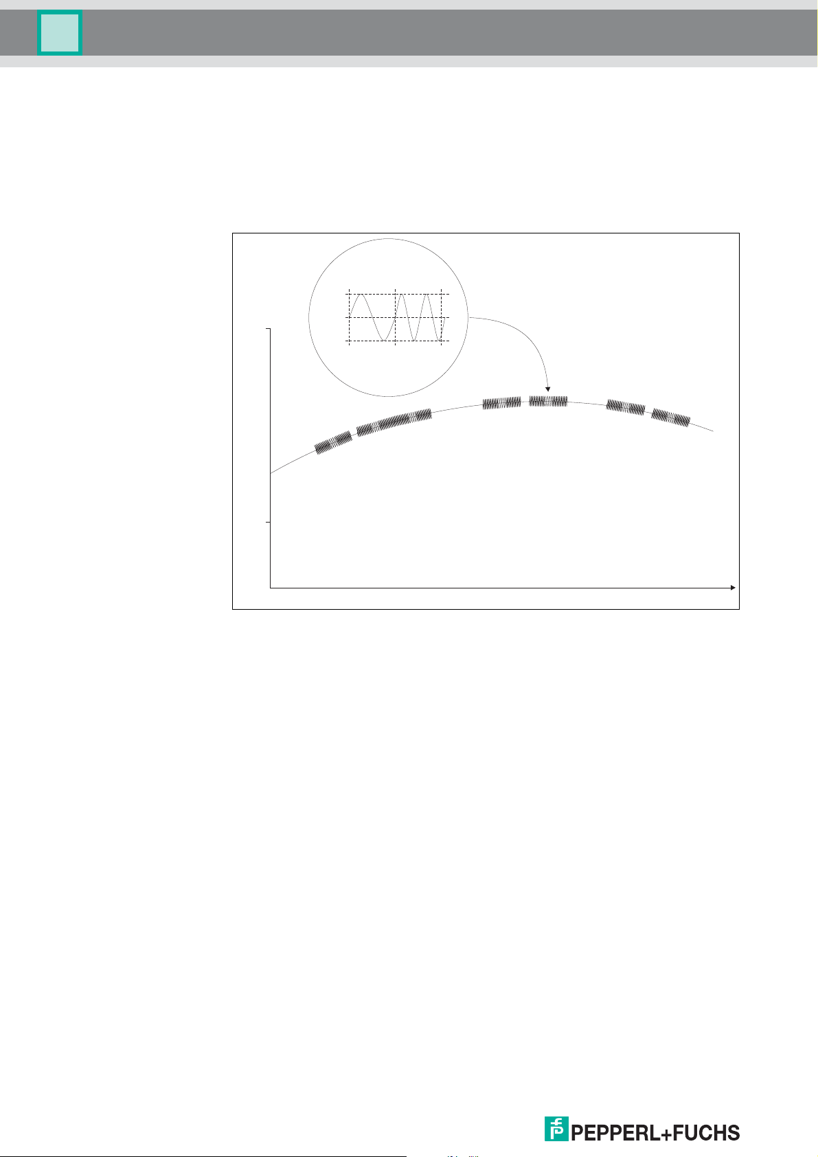
The high frequency HART signal consists of
the sinusoidal frequencies 1200 Hz and
2200 Hz. This signal has an average value of
zero, so that it does not affect the analog
signal. It is removed by standard analog input
circuit filtering.
Product specification
3.2 Description of the HART communication
The HART protocol (Highway Addressable Remote Transducer) is supported by
many conventional 4 mA ... 20 mA field devices, which thus enable digital
communication for configuration and servicing purposes. Many device parameters
and also the measured values themselves can thus be digitally transferred to and
from the device. This digital communication runs in parallel with the 4 mA ... 20 mA
signal on the same cable. This is possible through a current modulation, which is
superimposed on the user signal.
Figure 3.3 The modulated HART signal
HART is a Master-Slave protocol: a field device does only respond when requested
(except in "Burst mode"). The message duration is several hundred milliseconds, so
that between two and three messages can be transferred per second.
On HART, there are three groups of commands:
• The Universal commands; these must be supported by all field devices,
• the Common practice commands; these are pre-defined commands, suitable for
many field devices, which, if they are supported by the device, must be
implemented in the pre-defined form,
• device-specific commands; these are commands, which are particularly suitable
for this field device.
The HART Multiplexer contains commands in all three groups. Details of the
supported commands are given in section 9.1.
DOCT-0120D 06/2014
12

HART Multiplexer System KFD*-HM*-16
Product specification
3.3 System construction
3.3.1 System description
In process engineering plants, there are many field devices distributed over a large
area. The characteristic values of these field devices must be monitored, for
example, in the context of ISO 9000 and recorded and adapted to changes in
process parameters.
The HART Multiplex System from Pepperl+Fuchs enables on-line communication
between a PC and "smart" field devices that support the HART protocol.
SMART transmitters and intelligent valve positioners enable information such as
measurement range and tag number to be stored in the field device itself. Access to
these data is usually obtained using a handheld terminal. This means, that when
changes to information are required, connection to the field device must be carried
out "by hand".
When specific data has to be recorded in the context of quality assurance - in
accordance with ISO 9000 - this means that there is an increased demand on the
process control system or the DCS. For example, the data has to be cyclically
interrogated and then stored by the system in a database.
The HART Multiplex System from Pepperl+Fuchs provides the coupling between the
PC and the intelligent "HART capable" field devices. All access to the field device
takes place in parallel with the transfer of the 4 mA ... 20 mA measuring signal and
therefore has no affect on the processing of measured values by the process control
system.
3.3.2 Service station
The system thus provides a subordinate service interface. It is also possible to obtain
measured values through the HART Multiplex System. On field devices, which are
installed in hazardous areas, the coupling takes place on the safe area side of the
current repeaters.
Pepperl+Fuchs can supply the appropriate SMART transmitter power supplies
(e.g.KFD2-STC4-**) and SMART repeater (e.g.KFD2-STV4-**). Similarly, the
HART Multiplex System can also be connected to other SMART Ex-isolation stages.
This means that existing systems can be expanded very easily, thus taking full
advantage of the HART communication system.
The system comprises a max. of 31 HART Multiplexer Masters, which are connected
to the PC via a RS 485 interface. Each HART Multiplexer Master can control up to 15
HART Multiplexer Slaves. Each Multiplexer, irrespective of Master or Slave, can
connect up to 16 transmitters.
Thus one PC can be used to address up to 7936 field devices for the exchange of
data. Operation using a handheld terminal also remains possible, since the HART
protocol accepts two Masters in one system, i. e. PC and handheld terminal.
Besides the control system a PC is frequently used as the service station, with which
the parameter functions or data logging functions can be carried out. Operating
programs for the PC are available from various manufacturers (see section 3.3.3) to
provide the necessary back-up for this purpose.
However, in some cases the communication is provided by a process control system
via a RS 485 interface direct (via the HART Multiplexer) to the field devices without a
connected service station. But the low speed of the HART communication imposes
limitations on this method of operation.
DOCT-0120D 06/2014
13
HART Multiplexer System KFD*-HM*-16
Note
Product specification
3.3.3 Integration in the operating software (Asset Management Systems)
The full potential of the HART Multiplexer System is realized through integration in
modern Asset Management Systems such as PACTware
SIMATIC PDM (Siemens), AMS (Fisher-Rousemount), Cornerstone (Applied
System Technologies) and Valve Manager (Neles Automation). These operating
tools combine the device functions of the Multiplexer in the form of menu commands
in a unified interface providing a very convenient method of operation. The
presentation and description of the functions in the individual operating tools can be
very different, however; thus a generally applicable presentation is not possible here.
Information on the configuration, parameter assignment, operation and diagnostics
options of the Multiplexer is provided in the documentation accompanying the
various operating tools.
TM
(open source),
DOCT-0120D 06/2014
14
HART Multiplexer System KFD*-HM*-16
Note
Management
Software
KFD2-EB2
4 AT
!
KFD2-HMM-16
ON
13 14 15
19 20 21
16 17 18
ON
KFD0-HMS-16
78 9
10 11 12
Flex-InterfaceFlex-Interface
Converter
Power Rail insert
26 way ribbon cable
14 way ribbon cable
DIN Rail
up to 31 HART Multiplexer Masters
up to 15 HART Multiplexer Slaves per Master
24 VDC
RS 485
connection
Up to
16
field devices
Up to
16
field devices
DCS
RS 232
RS 485
Product specification
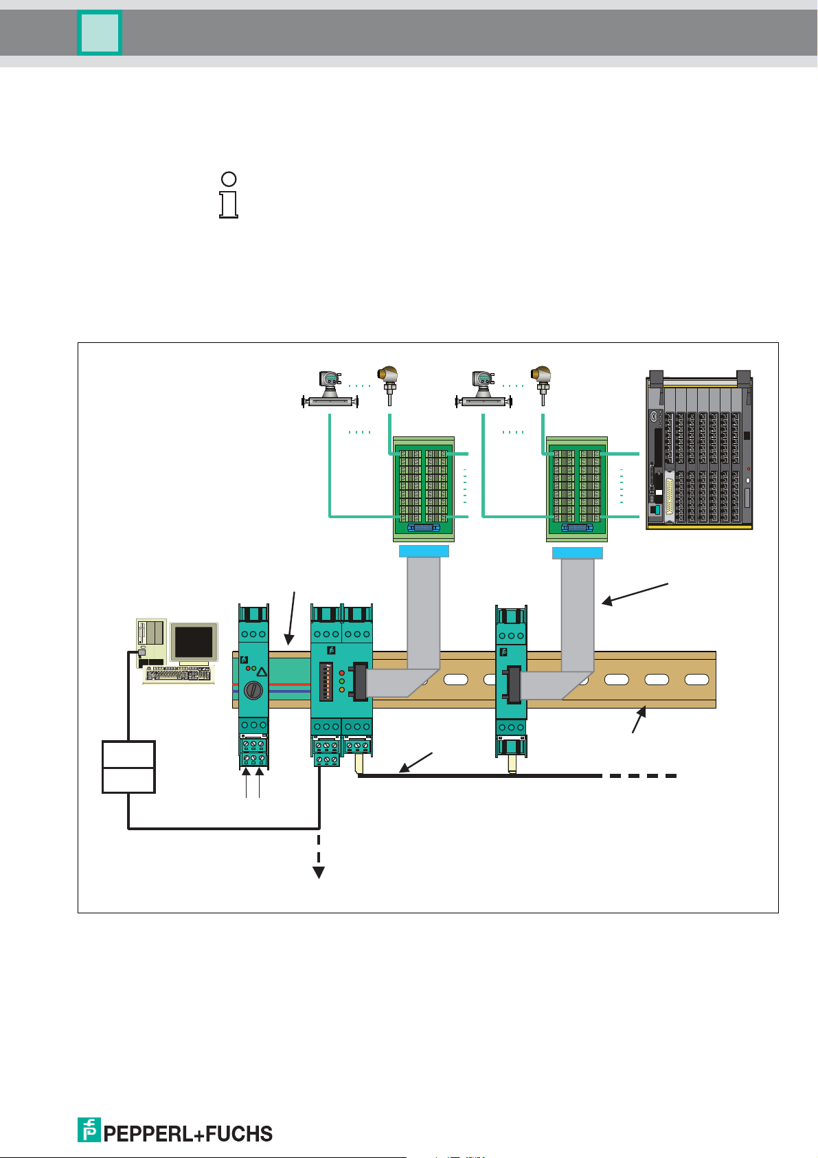
3.3.4 System construction
External assembly Multiplexer Master and Slaves are installed on Flex Interfaces, which transmits the
The wiring of the single I/O components of the HART product portfolio is done via a
Termination Board. Since a wide variety of Termination Boards is available, only the
basic wiring options should be described here.
Field devices and DCS are connected via Termination Boards in every case. More
detailed information to connection layout can be found in the data sheet of the
according Termination Board
signals via screw terminals. In this case the Termination Board provides the
connection to the Multiplexer parallel or serial. This assembly method is completely
independent of DCS and eventually used field barriers.
Figure 3.4 External assembly of Multiplexers
DOCT-0120D 06/2014
15
HART Multiplexer System KFD*-HM*-16
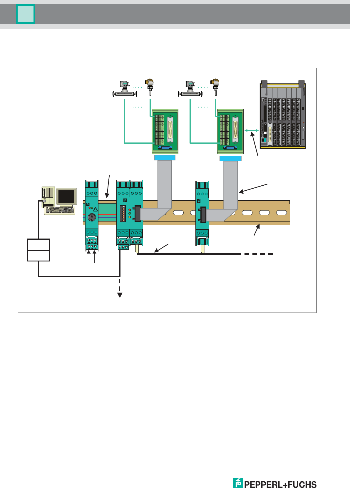
Product specification
Assembly integrated
in the DCS
Management
Software
Multiplexer Master and Slaves are installed on Flex Interfaces, which transmits the
signals via screw terminals and system cable to the DCS. In this case the
Termination Board provides the connection to the Multiplexer parallel or serial. The
Termination Boards are designed especially for individual DCS.
DCS
Flex-InterfaceFlex-Interface
Up to
16
field devices
Connection via
system connector
26 way ribbon cable
Power Rail insert
KFD2-EB2
!
Up to
field devices
KFD2-HMM-16
ON
ON
16
Converter
RS 232
RS 485
4 AT
78 9
10 11 12
24 VDC
RS 485
connection
Figure 3.5 Assembly integrated in the DCS
13 14 15
16 17 18
19 20 21
14 way ribbon cable
up to 15 HART Multiplexer Slaves per Master
up to 31 HART Multiplexer Masters
KFD0-HMS-16
DIN Rail
16
DOCT-0120D 06/2014
HART Multiplexer System KFD*-HM*-16
Management
Software
KFD2-EB2
4 AT
!
KFD2-HMM-16
ON
13 14 15
19 20 21
16 17 18
ON
KFD0-HMS-16
78 9
10 11 12
Converter
Power Rail insert
26 way ribbon cable
14 way ribbon cable
DIN Rail
up to 31 HART Multiplexer Masters
up to 15 HART Multiplexer Slaves per Master
24 VDC
RS 485
connection
Up to 16
field devices
Up to 16
field devices
DCS
Connection via
system connector
Redundant
power supply
Power supply
Redundant
power supply
Power supply
Motherboard
with isolator module
Motherboard
with isolator module
RS 232
RS 485
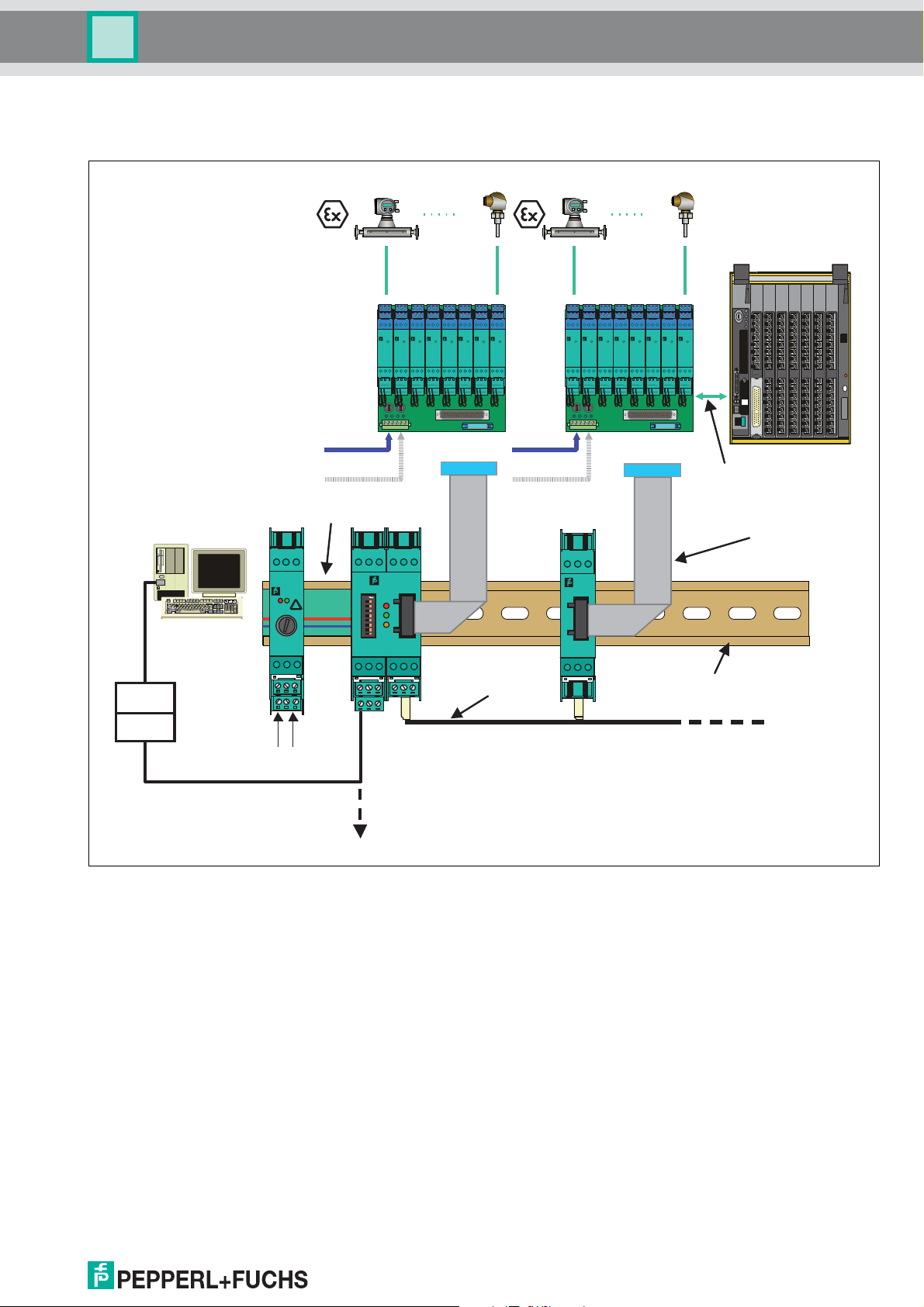
Product specification
Assembly integrated
in the K-System
When using the K-System of Pepperl+Fuchs the signals can be transmitted directly
from the Termination Boards of the K-System to the Multiplexer Master or Slave via a
system plug.
1 23
1 23
1 23
1 23
1 23
1 23
1 23
1 23
1 23
1 23
1 23
1 23
1 23
1 23
4 5 6
4 5 6
4 5 6
4 5 6
PWR
KFD2-
KFD2-
STC4-Ex2
STC4-Ex2
7 8 9
7 8 9
10
10
13 14 15
13 14 15
4 5 6
PWR
PWR
PWR
KFD2-
KFD2-
KFD2-
STC4-Ex2
STC4-Ex2
STC4-Ex2
7 8 9
7 8 9
7 8 9
10
10
10
13 14 15
13 14 15
13 14 15
1 23
4 5 6
4 5 6
4 5 6
PWR
PWR
PWR
PWR
KFD2-
KFD2-
KFD2-
STC4-Ex2
STC4-Ex2
STC4-Ex2
7 8 9
7 8 9
7 8 9
10
10
10
13 14 15
13 14 15
13 14 15
4 5 6
4 5 6
4 5 6
4 5 6
PWR
KFD2-
KFD2-
STC4-Ex2
STC4-Ex2
7 8 9
7 8 9
10
10
13 14 15
13 14 15
4 5 6
PWR
PWR
PWR
KFD2-
KFD2-
KFD2-
STC4-Ex2
STC4-Ex2
STC4-Ex2
7 8 9
7 8 9
7 8 9
10
10
10
13 14 15
13 14 15
13 14 15
1 23
4 5 6
4 5 6
4 5 6
PWR
PWR
PWR
PWR
KFD2-
KFD2-
KFD2-
STC4-Ex2
STC4-Ex2
STC4-Ex2
7 8 9
7 8 9
7 8 9
10
10
10
13 14 15
13 14 15
13 14 15
Figure 3.6 Assembly integrated in the K-System
DOCT-0120D 06/2014
17
HART Multiplexer System KFD*-HM*-16
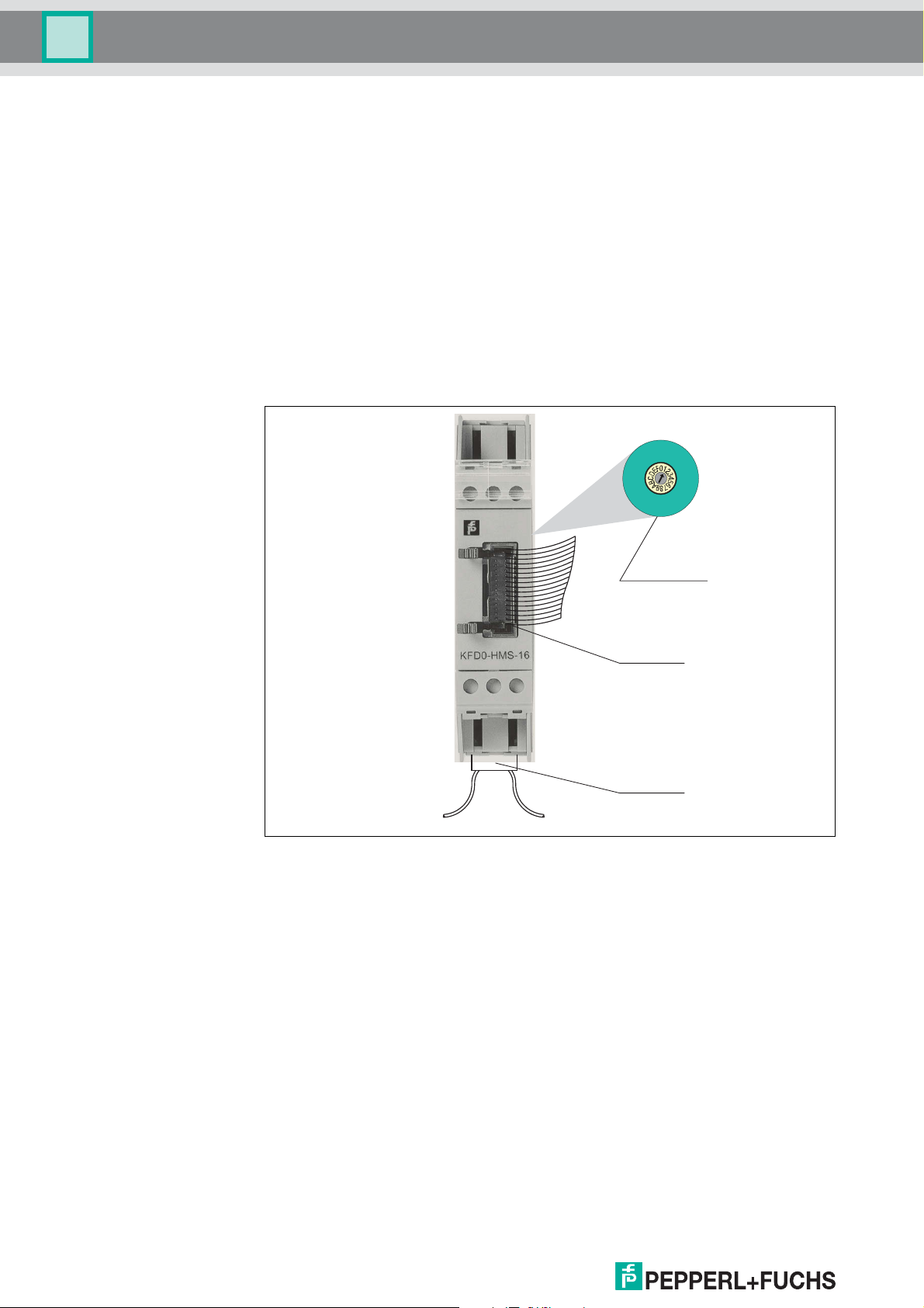
1
26
Rotary switch
26 pin
Connector
14 pin
Connector
Product specification
3.3.5 HART Multiplexer Slave
The HART Multiplexer Slave is supplied from the HART Multiplexer Master via the
14-core flat cable. The contacting of the flat cable is provided via IDC connectors, so
that the cable can be tapped at any position. By this means, the power supply and
data cables are looped on from station to station. The address 1 ... 15 is set via a 16step rotary switch. Address 0 is reserved for the Multiplexer Master and must
therefore not be used. If a number of Slaves are operated on the KFD2-HMM-16,
different addresses must be assigned. The sequence therefore plays no role in this.
The analog signals are fed via a 26 core flat cable into the KFD0-HMS-16. 16 of
these are intended for the HART signal of the analog instrument circuit (the
remaining 10 are to ground) (for the assignment, see section 9.2).
The minimum load resistance of the analog measuring circuit is 230 (minimum
load impedance in accordance with HART specification), the maximum resistive load
being 500 . Load resistances of up to 1000 are possible, however, resistance
values greater than 500 can interfere with the HART communication.
Slave connection HART Multiplexer Masters and Slaves must be connected together via a separate K-
3.3.6 Operation
18
Figure 3.7 Front view HART Multiplexer Slave
HM14 flat cable.
The length of cable required should be stated when ordering. Hence the wiring of the
HART Multiplexer is significantly simplified and the danger of wiring faults is
excluded.
The Multiplexer also functions as a HART device (see also section 5.4.5). However,
due to the incorporation into the operating software of the service station (see
section 3.3.3), this remains concealed from the user. The HART commands that are
supported by the Multiplexer can be found in section 9.1.
For HART communication with the transmitters, the commands of the service station
are passed through without modifications.
DOCT-0120D 06/2014
HART Multiplexer System KFD*-HM*-16
Power 24 V DC
Note
Installation
4 Installation
4.1 Mounting
The K-System allows three different types of mounting:
1. wall or panel mounting
2. mounting on 35 mm DIN EN 60715 mounting rail
– TH 35-7.5 (installation height 7.5 mm)
– TH 35-15 (installation height 15 mm, material thickness 1.5 mm)
3. mounting on 35 mm DIN rail with a Power Rail insert
Wall or panel mounting Panel mounting is only recommended when a very small number of isolation
components must be installed.
Mounting the device on the wall.
Pull the two clip fasteners out of the back of the device until the clips audibly click
into place.
Fasten the device to the wall or panel with 3 mm screws.
The device is mounted
Mounting on
DIN rail
When mounting on DIN rail, the device is simply snapped into place.
Figure 4.1
The wiring effort for power supply with the isolation modules of the K-Systems can
be greatly reduced by using Power Rail.
DOCT-0120D 06/2014
19
HART Multiplexer System KFD*-HM*-16
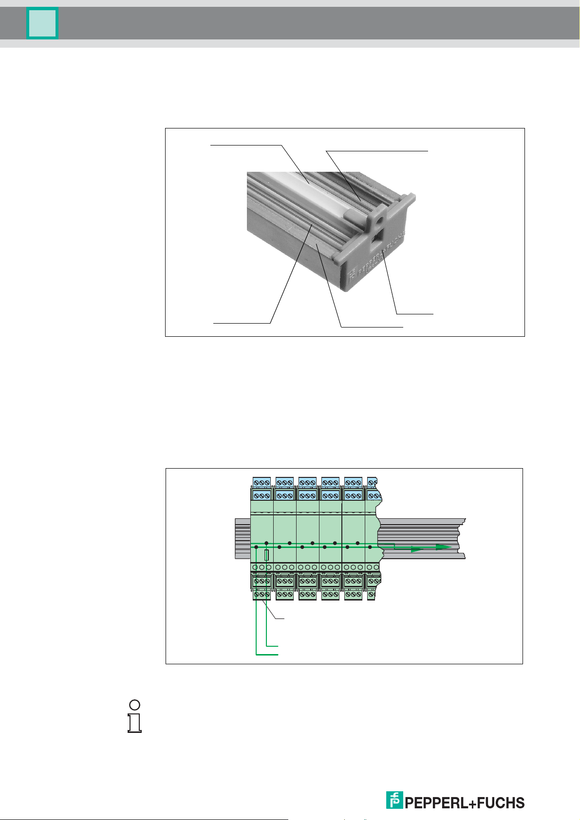
2 leads for
power supply
End cap
Power Rail insert
1 lead for centralized error
UPR-03-*
DIN mounting rail
Power 24 V DC
Power feed module
KFD2-EB*.***.*
Note
Installation
Mounting on DIN rail with
Power Rail
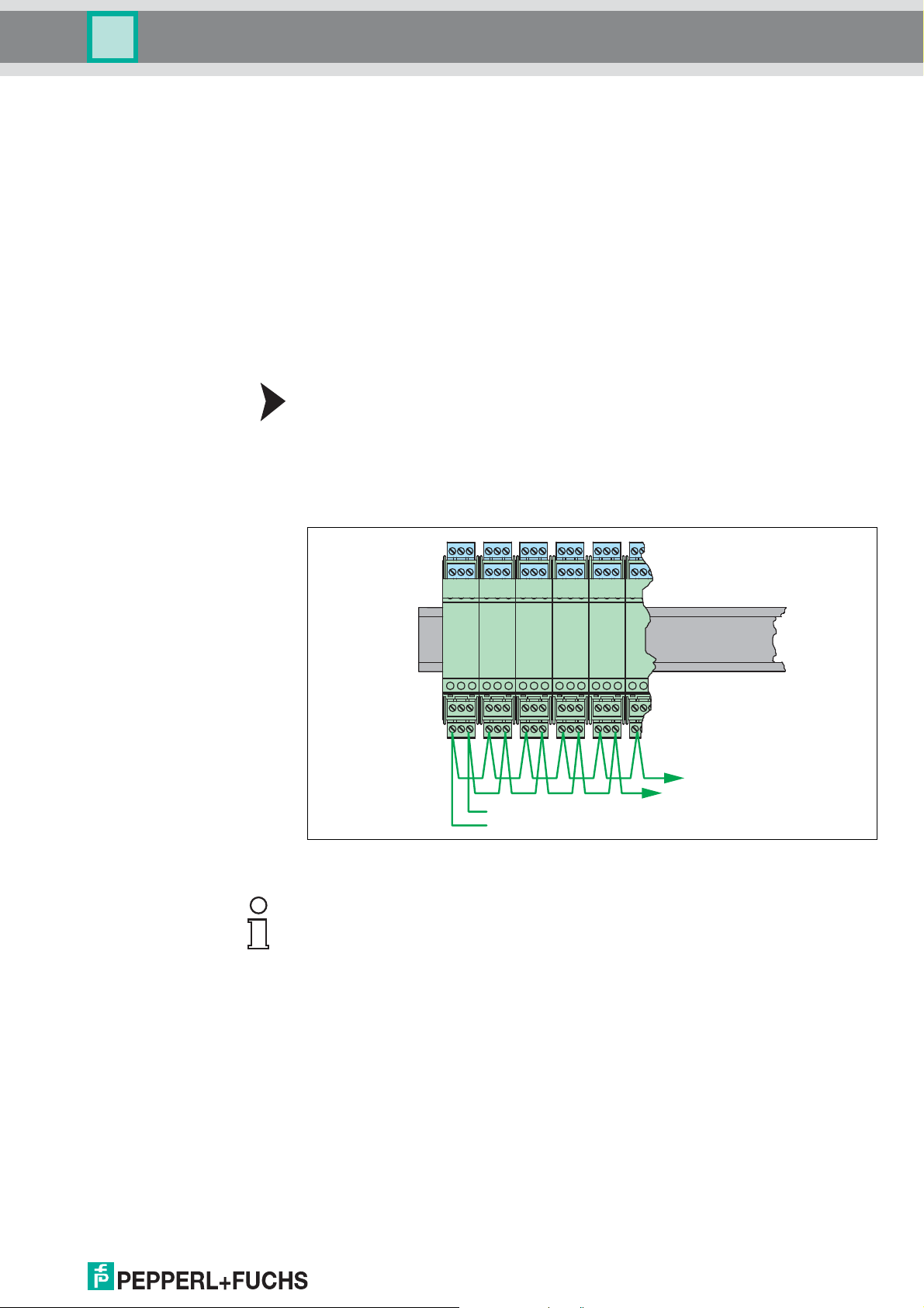
The Power Rail UPR-03-* is an insert for a DIN rail which Pepperl+Fuchs has
developed for this application.
The Power Rail provides two leads for power supply of the modules and one lead for
centralized error messages. The devices of the K-System are supplied with power
through these two leads.
Figure 4.2
Standard devices of types KFD2-... and KCD2-... have gold-plated contacts to
connect to the power supply rails of the Power Rail. By snapping it onto the DIN rail,
the device automatically receives power. Thus separate wiring of the power supply is
eliminated. An included cover provides for the mechanical and electrical protection
of unused spaces. Furthermore, any reserved spaces are automatically connected to
the power supply.
Third-party devices which can be mounted on a DIN EN 60715 mounting rail can
easily be mounted on the Power Rail as well. Mixed devices from different device
manufacturers are thus possible.
Figure 4.3
When supplying power via the Power Rail, the wiring effort is greatly reduced.
Moreover, there is the option of the centralized error message and redundant power
supply. Failure of the power supply is indicated through the message contact of the
power supply component.
20
DOCT-0120D 06/2014
 Loading...