

Page 1
24 V DC
Zone 2
Div. 2
Zone 0, 1, 2
Div. 1, 2
KFD2-UFT-Ex2.D
3-
1+
16
17
18
10
11
12
I
II
III
IV
13+
1415+
78+
V
6-
4+
10 kΩ 10 kΩ
400 Ω ≤ R ≤ 2 kΩ
10 kΩ 10 kΩ
400 Ω ≤ R ≤ 2 kΩ
24 V DC
23+
24-
Power Rail
24 V DCERR
I
II
19+
20-
21+
mA
Germany: +49 621 776 2222Pepperl+Fuchs Group
Refer to "General Notes Relating to Pepperl+Fuchs Product Information".
USA: +1 330 486 0002 Singapore: +65 6779 9091
www.pepperl-fuchs.com pa-info@us.pepperl-fuchs.com pa-info@sg.pepperl-fuchs.com
pa-info@de.pepperl-fuchs.com
Function
Frequency Converter with Direction and Synchronization Monitor
KFD2-UFT-Ex2.D
2-channel isolated barrier
<
24 V DC supply (Power Rail)
<
Dry contact or NAMUR inputs
<
Input frequency 1 mHz ... 1 kHz
<
Current output 0/4 mA ... 20 mA
<
Relay contact and transistor output
<
Start-up override
<
Configurable by PACTware or keypad
<
Line fault detection (LFD)
<
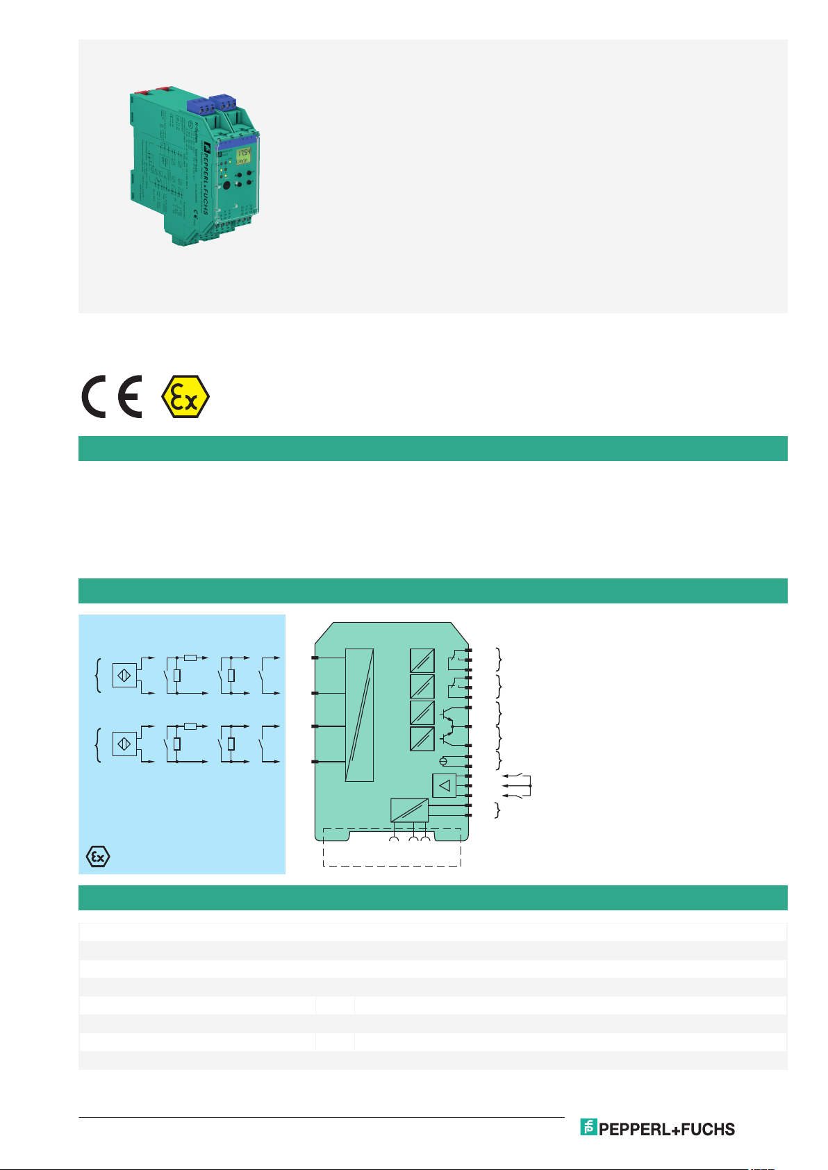
This isolated barrier is used for intrinsic safety applications. It analyzes 2 digital signals (NAMUR sensor/mechanical contact) from a hazardous
area and functions as a rotation direction indicator, slip monitor, frequency monitor or synchronization monitor.
Each proximity sensor or switch controls a passive transistor output. The 2 relay outputs indicate if the input signal is above or below the trip value
or the rotational direction.
The analog output can be programmed to be proportional to the input frequency or slip differential.
The unit is easily programmed by the use of a keypad located on the front of the unit or with the PACTware™ configuration software.
Line fault detection of the field current is indicated by a red LED.
For additional information, refer to the manual and www.pepperl-fuchs.com.
Connection
Technical Data
General specifications
Signal type Digital Input
Supply
Connection terminals 23+, 24- or power feed module/Power Rail
Rated voltage U
Rated current I
Power dissipation 2.2 W
Power consumption 2.5 W
Release date: 2020-09-23 Date of issue: 2020-09-23 Filename: 231200_eng.pdf
r
r
20 ... 30 V DC
approx. 130 mA
1
Page 2

KFD2-UFT-Ex2.D
Germany: +49 621 776 2222Pepperl+Fuchs Group
Refer to "General Notes Relating to Pepperl+Fuchs Product Information".
USA: +1 330 486 0002 Singapore: +65 6779 9091
www.pepperl-fuchs.com pa-info@us.pepperl-fuchs.com pa-info@sg.pepperl-fuchs.com
pa-info@de.pepperl-fuchs.com
Technical Data
Interface
Programming interface programming socket
Input
Connection side field side
Connection input I: terminals 1+, 3-
Input I, II 2-wire sensor, sensor acc. to EN 60947-5-6 (NAMUR) or mechanical contact
Open circuit voltage/short-circuit current 8.2 V / 10 mA
Pulse duration min. 250 µs , overlap on direction of rotation signal: ≥ 125 µs
Input frequency rotation direction monitoring 0.001 ... 1000 Hz slip monitoring 10 ... 1000 Hz
Line fault detection breakage I ≤ 0.15 mA; short-circuit I > 6.5 mA
Input III, IV
Active/Passive I > 4 mA (for min. 100 ms) / I < 1.5 mA
Open circuit voltage/short-circuit current 18 V / 5 mA
Output
Connection side control side
Connection output I: terminals 10, 11, 12
Output I, II signal , relay
Contact loading 250 V AC / 2 A / cos φ ≥ 0.7 ; 40 V DC / 2 A
Mechanical life 5 x 10⁷ switching cycles
Energized/De-energized delay approx. 20 ms / approx. 20 ms
Output III and IV signal , electronic output, passive
Contact loading 40 V DC
Signal level 1-signal: (external voltage) - 2.5 V max. for 10 mA or 3 V max. for 100 mA (100 mA,
Output V analog
Current range 0 ... 20 mA or 4 ... 20 mA
Open loop voltage max. 24 V DC
Load max. 650 Ω
Fault signal downscale I ≤ 3.6 mA, upscale I ≥ 21.5 mA (acc. NAMUR NE43)
Collective error message Power Rail
Transfer characteristics
Input I and II
Measurement range 0.001 ... 1000 Hz
Resolution slip monitoring: 1% frequency measurement: 0,1% of measured value; but >0.001Hz
Accuracy slip monitoring: 1% frequency measurement: 0.5% of measured value; but >0.001Hz
Measuring time frequency measurement: < 100 ms
Influence of ambient temperature 0.003 %/K (30 ppm)
Output I, II
Response delay ≤ 200 ms
Output V
Resolution < 10 µA
Accuracy < 30 µA
Influence of ambient temperature 0.005 %/K (50 ppm)
Galvanic isolation
Input I, II/other circuits reinforced insulation according to IEC/EN 61010-1, rated insulation voltage 300 V
Input III, IV/power supply and collective error functional insulation acc. to IEC 62103, rated insulation voltage 50 V
Output I, II/other circuits reinforced insulation according to IEC/EN 61010-1, rated insulation voltage 300 V
Mutual output I, II, III reinforced insulation according to IEC/EN 61010-1, rated insulation voltage 300 V
Release date: 2020-09-23 Date of issue: 2020-09-23 Filename: 231200_eng.pdf
input II: terminals 4+, 6input III: terminals 13+, 14- (control input 1)
input IV: terminals 15+, 14- (control input 2)
output II: terminals 16, 17, 18
output III: terminals 19+, 20output IV: terminals 21+, 20output V: terminals 7-, 8+
short-circuit proof) -2.5 V (50 mA, short-circuit/overload proof)
0-signal: switched off (off-state current ≤ 10 µA)
eff
eff
eff
eff
2
Page 3

Technical Data
Germany: +49 621 776 2222Pepperl+Fuchs Group
Refer to "General Notes Relating to Pepperl+Fuchs Product Information".
USA: +1 330 486 0002 Singapore: +65 6779 9091
www.pepperl-fuchs.com pa-info@us.pepperl-fuchs.com pa-info@sg.pepperl-fuchs.com
pa-info@de.pepperl-fuchs.com
KFD2-UFT-Ex2.D
Mutual output I, II, IV reinforced insulation according to IEC/EN 61010-1, rated insulation voltage 300 V
Output III, IV/power supply and collective error basic insulation according to IEC/EN 61010-1, rated insulation voltage 50 V
Output III, IV/input III, IV basic insulation according to IEC/EN 61010-1, rated insulation voltage 50 V
Output III, IV/V basic insulation according to IEC/EN 61010-1, rated insulation voltage 50 V
Output V/power supply and collective error functional insulation acc. to IEC 62103, rated insulation voltage 50 V
Interface/power supply and collective error functional insulation acc. to IEC 62103, rated insulation voltage 50 V
Interface/output III, IV basic insulation according to IEC/EN 61010-1, rated insulation voltage 50 V
eff
eff
eff
eff
eff
eff
Indicators/settings
Display elements LEDs , display
Control elements Control panel
Configuration via operating buttons
via PACTware
Labeling space for labeling at the front
Directive conformity
Electromagnetic compatibility
Directive 2014/30/EU EN 61326-1:2013 (industrial locations)
Low voltage
Directive 2014/35/EU EN 61010-1:2010
Conformity
Electromagnetic compatibility NE 21:2006
Degree of protection IEC 60529:2001
Input EN 60947-5-6:2000
Ambient conditions
Ambient temperature -20 ... 60 °C (-4 ... 140 °F)
Mechanical specifications
Degree of protection IP20
Connection screw terminals
Mass 300 g
Dimensions 40 x 119 x 115 mm (1.6 x 4.7 x 4.5 inch) , housing type C3
Mounting on 35 mm DIN mounting rail acc. to EN 60715:2001
Data for application in connection with hazardous areas
EU-type examination certificate TÜV 99 ATEX 1471
Marking 1 II (1)G [Ex ia Ga] IIC
1 II (1)D [Ex ia Da] IIIC
1 I (M1) [Ex ia Ma] I
Supply
Maximum safe voltage U
40 V DC (Attention! Um is no rated voltage.)
m
Input I and II terminals 1+, 3-; 4+, 6-: Ex ia
Voltage U
Current I
Power P
o
o
o
10.1 V
13.5 mA
34 mW (linear characteristic)
Input III and IV terminals 13+, 14-; 15+, 14- non-intrinsically safe
Maximum safe voltage U
m
40 V (Attention! Um is no rated voltage.)
Output I, II terminals 10, 11, 12; 16, 17, 18 non-intrinsically safe
Maximum safe voltage U
253 V (Attention! The rated voltage can be lower.)
m
Contact loading 253 V AC/2 A/cos φ > 0.7; 40 V DC/2 A resistive load (TÜV 99 ATEX 1471)
eff
Output III and IV terminals 19, 20, 21 non-intrinsically safe
Maximum safe voltage U
m
U
40 V DC (Attention! Um is no rated voltage.)
m
Output V terminals 8+, 7- non-intrinsically safe
Maximum safe voltage U
m
U
40 V DC (Attention! Um is no rated voltage.)
m
Interface RS 232
Maximum safe voltage U
40 V (Attention! Um is no rated voltage.)
m
Certificate TÜV 02 ATEX 1885 X
Release date: 2020-09-23 Date of issue: 2020-09-23 Filename: 231200_eng.pdf
3
Page 4

ESC
OK
KFD2-UFTEx2.D
RS232
PWR1
1 2
324
IN/
CHK
OUT
19 21
15
9
13
7
20
14
8
22 24
18
12
16
10
23
17
11
132 465
Front view
LED green:
Power supply
LED yellow/red:
Input pulses/
fault signal
LED yellow:
Output I ... IV
Removable
terminals
green
Removable
terminals
blue
Keypad
LC display
Programming jack
Place for labeling
KFD2-UFT-Ex2.D
Germany: +49 621 776 2222Pepperl+Fuchs Group
Refer to "General Notes Relating to Pepperl+Fuchs Product Information".
USA: +1 330 486 0002 Singapore: +65 6779 9091
www.pepperl-fuchs.com pa-info@us.pepperl-fuchs.com pa-info@sg.pepperl-fuchs.com
pa-info@de.pepperl-fuchs.com
Technical Data
Marking 1 II 3G Ex nA nC IIC T4 Gc
Output I, II
Contact loading 50 V AC/2 A/cos φ > 0.7; 40 V DC/1 A resistive load
Galvanic isolation
Input I, II/other circuits safe electrical isolation acc. to IEC/EN 60079-11, voltage peak value 375 V
Directive conformity
Directive 2014/34/EU EN 60079-0:2012+A11:2013 , EN 60079-11:2012 , EN 60079-15:2010
International approvals
FM approval
Control drawing 16-538FM-12
UL approval E223772
IECEx approval IECEx TUN 04.0007
Approved for [Ex ia Ga] IIC, [Ex ia Da] IIIC, [Ex ia Ma] I
General information
Supplementary information Observe the certificates, declarations of conformity, instruction manuals, and manuals
where applicable. For information see www.pepperl-fuchs.com.
Assembly
Accessories
DTM Interface
Technology
PACTware 5.X FDT Framework
K-ADP-USB
KFD2-EB2 Power Feed Module
Release date: 2020-09-23 Date of issue: 2020-09-23 Filename: 231200_eng.pdf
4
Page 5

Accessories
Germany: +49 621 776 2222Pepperl+Fuchs Group
Refer to "General Notes Relating to Pepperl+Fuchs Product Information".
USA: +1 330 486 0002 Singapore: +65 6779 9091
www.pepperl-fuchs.com pa-info@us.pepperl-fuchs.com pa-info@sg.pepperl-fuchs.com
pa-info@de.pepperl-fuchs.com
UPR-03 Universal Power Rail with end caps and cover, 3 conductors, length: 2 m
UPR-03-M Universal Power Rail with end caps and cover, 3 conductors, length: 1,6 m
UPR-03-S Universal Power Rail with end caps and cover, 3 conductors, length: 0.8 m
K-DUCT-BU
K-DUCT-BU-UPR-03 Profile rail with UPR-03- * insert, 3 conductors, wiring comb field side blue
KFD2-UFT-Ex2.D
Release date: 2020-09-23 Date of issue: 2020-09-23 Filename: 231200_eng.pdf
5
Page 6
Germany: +49 621 776 2222Pepperl+Fuchs Group
Refer to "General Notes Relating to Pepperl+Fuchs Product Information".
USA: +1 330 486 0002 Singapore: +65 6779 9091
www.pepperl-fuchs.com pa-info@us.pepperl-fuchs.com pa-info@sg.pepperl-fuchs.com
pa-info@de.pepperl-fuchs.com
Frequency Converter with Direction and Synchronization Monitor
0.1
1
0.2
0.15
2
0.3
3
0.4
4
0.5
0 50 150 200 250100
I (A)
U (V)
1
KFD2-UFT-Ex2.D
Operation
The device processes two input frequencies up to a max. of 1 kHz. The following functions are provided by the device:
• Frequency measurement with freely adjustable trip value monitoring for high and low alarm as well as for frequency-currentconversion (0/4 mA ... 20 mA)
• Slip monitoring: The slip is calculated from the two input frequencies at channel I and II. If the freely parameterisable trip value
is exceeded, the respective output switches.
• Rotation direction signalling: The rotation direction is evaluated from the two input signals with the same frequency and a
phase shift of 90°. The corresponding outputs switch according to the direction of rotation.
• The frequency monitoring can be used in combination with rotation direction signalling or slip monitoring.
• Synchronisation monitor: The synchronisation monitor compares the pulse counts of the two inputs. If the measured
difference in the pulses is greater than the programmed value the corresponding outputs are switching.
The two electronic outputs serve to repeat the input signals.
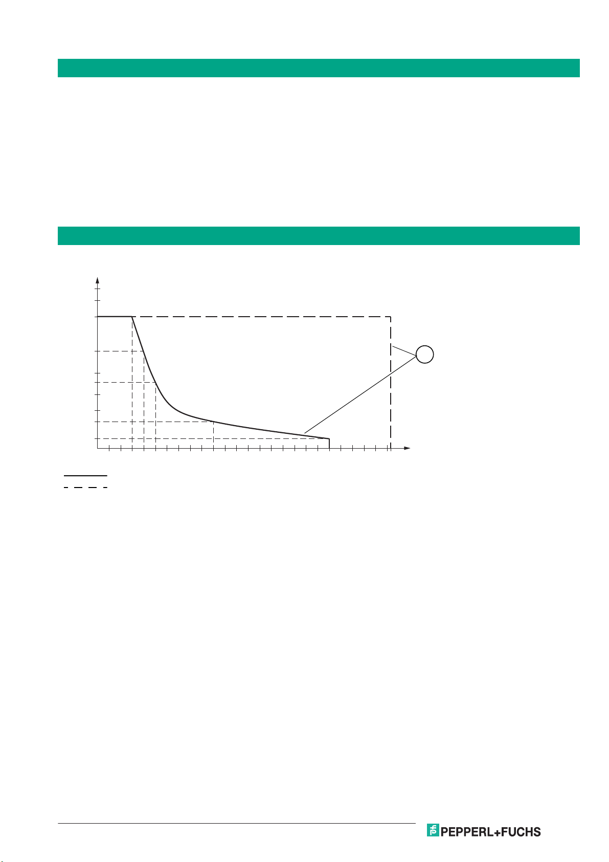
Characteristic Curve
Maximum Switching Power of Output Contacts
Resistive load DC
Resistive load AC
1 max. 105 switching cycles
Release date: 2020-09-23 Date of issue: 2020-09-23 Filename: 231200_eng.pdf
6
 Loading...