

Page 1
SMART Transmitter Power Supply
3
Zone 0, 1, 2
Div. 1, 2
KFD2-STC4-Ex1.2O.H
3
5-
6+
1+
2-
7-
8+
9
250
HART
HART
mA
mA
HART
10-
11+
12
250
HART
24 V DC
14+
15-
Power Rail
24 V DC
I
II
Zone 2
Div. 2
Germany: +49 621 776 2222Pepperl+Fuchs Group
Refer to "General Notes Relating to Pepperl+Fuchs Product Information".
USA: +1 330 486 0002 Singapore: +65 6779 9091
www.pepperl-fuchs.com pa-info@us.pepperl-fuchs.com pa-info@sg.pepperl-fuchs.com
pa-info@de.pepperl-fuchs.com
KFD2-STC4-Ex1.2O.H
1-channel isolated barrier
<
24 V DC supply (Power Rail)
<
Input 2-wire and 3-wire SMART transmitters and 2-wire SMART
<
current sources
Signal splitter (1 input and 2 outputs)
<
Dual output 0/4 mA ... 20 mA
<
Terminal blocks with test sockets
<
High field voltage 17.6 V DC
<
Up to SIL 3 acc. to IEC 61508
<
Input 0/4 mA ... 20 mA2 x Output 0/4 mA ... 20 mA
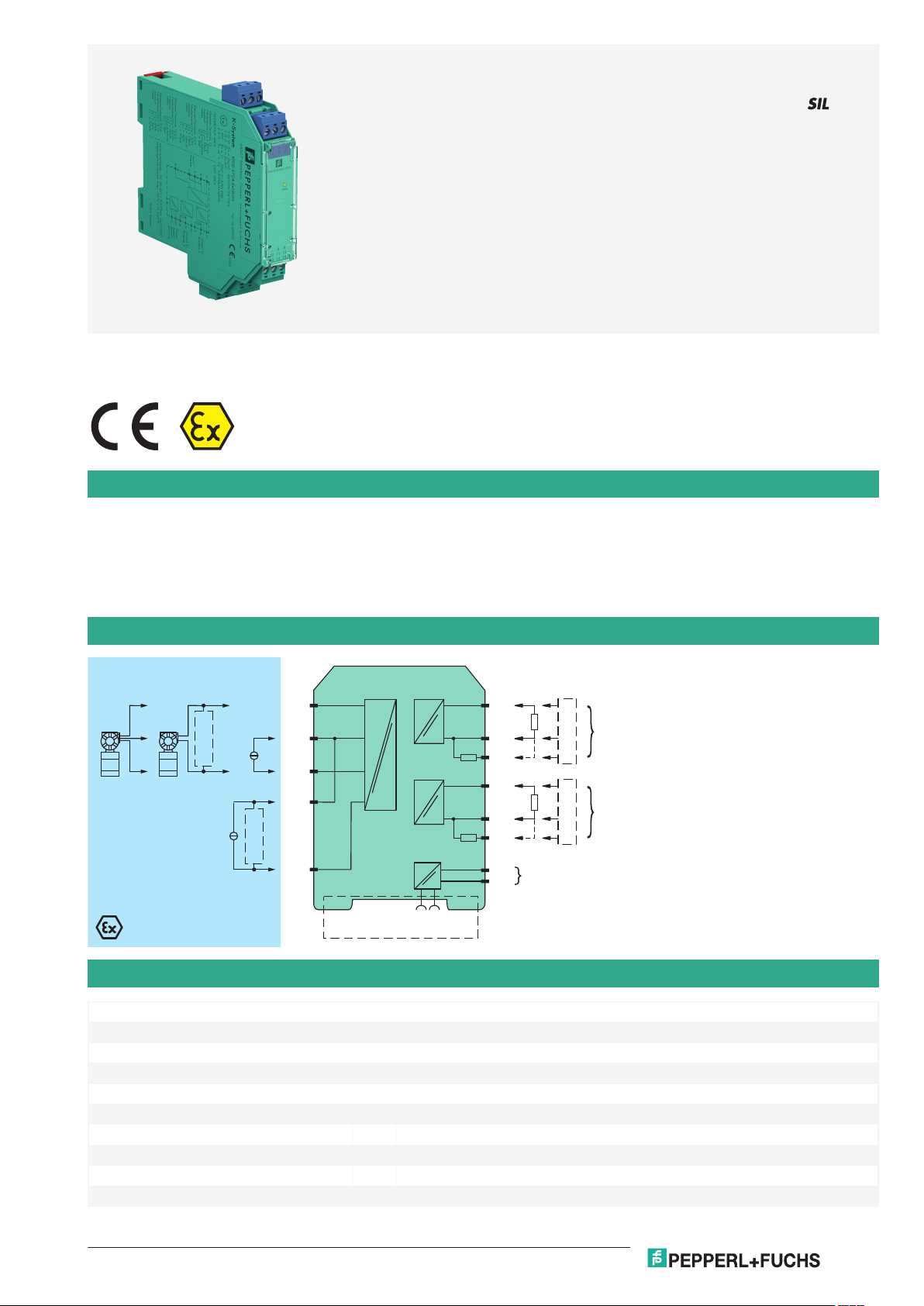
Function
This isolated barrier is used for intrinsic safety applications.
The device supplies 2-wire and 3-wire SMART transmitters with higher output voltage in a hazardous area, and can also be used with 2-wire
SMART current sources.
It transfers the analog input signal to the safe area as two isolated current values.
Digital signals may be superimposed on the input signal in the hazardous or safe area and are transferred bi-directionally.
If the HART communication resistance in the loop is too low, the internal resistance of 250 Ω between terminals 8 and 9 can be used.
Test sockets for the connection of HART communicators are integrated into the terminals of the device.
Connection
Technical Data
General specifications
Signal type Analog input
Functional safety related parameters
Safety Integrity Level (SIL) SIL 3
Supply
Connection Power Rail or terminals 14+, 15Rated voltage U
Ripple within the supply tolerance
Power dissipation 1.9 W
Power consumption 2.5 W
Release date: 2020-09-23 Date of issue: 2020-09-23 Filename: 283698_eng.pdf
r
20 ... 35 V DC
1
Page 2

SMART Transmitter Power Supply KFD2-STC4-Ex1.2O.H
Germany: +49 621 776 2222Pepperl+Fuchs Group
Refer to "General Notes Relating to Pepperl+Fuchs Product Information".
USA: +1 330 486 0002 Singapore: +65 6779 9091
www.pepperl-fuchs.com pa-info@us.pepperl-fuchs.com pa-info@sg.pepperl-fuchs.com
pa-info@de.pepperl-fuchs.com
Technical Data
Input
Connection side field side
Connection terminals 1+, 2-, 3 or 5-, 6+
Input signal 0/4 ... 20 mA
Open circuit voltage/short-circuit current terminals 1+, 3-: 24.2 V / 38 mA
Voltage drop terminals 5, 6 : ≤ 2.4 V at 20 mA
Input resistance terminals 2-, 3: max. 76 Ω
Available voltage terminals 1+, 3: ≥ 17.6 V at 20 mA
Output
Connection side control side
Connection terminals 7-, 8+,9; 10-, 11+,12
Load 0 ... 550 Ω at 20 mA
Output signal 0/4 ... 20 mA (overload > 25 mA)
Ripple max. 50 µA
Transfer characteristics
Deviation at 20 °C (68 °F), 0/4 ... 20 mA
Influence of ambient temperature 0.25 µA/K
Frequency range field side into the control side: bandwidth with 0.5 Vpp signal 0 ... 7.5 kHz (-3 dB)
Settling time 200 µs
Rise time/fall time 20 µs
Galvanic isolation
Output/power supply functional insulation, rated insulation voltage 50 V AC
Output/Output functional insulation, rated insulation voltage 50 V AC
Indicators/settings
Display elements LED
Labeling space for labeling at the front
Directive conformity
Electromagnetic compatibility
Directive 2014/30/EU EN 61326-1:2013 (industrial locations)
Conformity
Electromagnetic compatibility NE 21:2011
Degree of protection IEC 60529:2001
Protection against electrical shock UL 61010-1:2012
Ambient conditions
Ambient temperature -20 ... 60 °C (-4 ... 140 °F)
Mechanical specifications
Degree of protection IP20
Connection screw terminals
Mass approx. 200 g
Dimensions 20 x 124 x 115 mm (0.8 x 4.9 x 4.5 inch) , housing type B2
Mounting on 35 mm DIN mounting rail acc. to EN 60715:2001
Data for application in connection with hazardous areas
EU-type examination certificate BAS 99 ATEX 7060 X
Marking 1 II (1)G [Ex ia Ga] IIC , 1 II (1)D [Ex ia Da] IIIC , 1 I (M1) [Ex ia Ma] I
Input [Ex ia Ga] IIC, [Ex ia Da] IIIC, [Ex ia Ma] I
Supply
Maximum safe voltage U
Equipment terminals 1+, 3-
Voltage U
Current I
Power P
Release date: 2020-09-23 Date of issue: 2020-09-23 Filename: 283698_eng.pdf
o
o
o
terminals 1+, 3: max. 500 Ω (250 Ω load)
rms
≤ 10 µA incl. calibration, linearity, hysteresis, loads and fluctuations of supply voltage
control side into the field side: bandwidth with 0.5 Vpp signal 0.3 ... 7.5 kHz (-3 dB)
250 V (Attention! The rated voltage can be lower.)
m
27.2 V
93 mA
632 mW
2
Page 3

SMART Transmitter Power Supply KFD2-STC4-Ex1.2O.H
Germany: +49 621 776 2222Pepperl+Fuchs Group
Refer to "General Notes Relating to Pepperl+Fuchs Product Information".
USA: +1 330 486 0002 Singapore: +65 6779 9091
www.pepperl-fuchs.com pa-info@us.pepperl-fuchs.com pa-info@sg.pepperl-fuchs.com
pa-info@de.pepperl-fuchs.com
Technical Data
Internal capacitance C
i
12 nF
Internal inductance Li 0 mH
Equipment terminals 2-, 3
Voltage U
Current I
Voltage U
Current I
Power P
i
i
o
o
o
30 V
117 mA
3.5 V
73 mA
64 mW
Equipment terminals 1+, 2 / 3-
Voltage U
Current I
Power P
o
o
o
Internal capacitance C
i
27.2 V
117 mA
639 mW
12 nF
Internal inductance Li 0 mH
Equipment terminals 5-, 6+
Voltage U
Current I
Voltage U
Current I
i
i
o
o
Internal capacitance C
i
30 V
117 mA
8.7 V
0 mA
0 nF
Internal inductance Li 0 mH
Output
Maximum safe voltage U
250 V (Attention! The rated voltage can be lower.)
m
Certificate TÜV 99 ATEX 1499 X
Marking 1 II 3G Ex nA II T4 [device in zone 2]
Galvanic isolation
Input/Output safe electrical isolation acc. to IEC/EN 60079-11, voltage peak value 375 V
Input/power supply safe electrical isolation acc. to IEC/EN 60079-11, voltage peak value 375 V
Directive conformity
Directive 2014/34/EU EN 60079-0:2012+A11:2013 , EN 60079-11:2012 , EN 60079-15:2010
International approvals
UL approval
Control drawing 116-0428 (cULus)
IECEx approval IECEx BAS 04.0016X
IECEx CML 15.0055X
Approved for [Ex ia Ga] IIC, [Ex ia Da] IIIC, [Ex ia Ma] I
Ex nA IIC T4 Gc
General information
Note Both output loads must be connected to ensure complete and correct operation within
the technical specification.
Open circuit of one of the two outputs will not affect the connected output, but would
result in a loss of transmitter supply voltage of up to 0.7 Volt.
Supplementary information Observe the certificates, declarations of conformity, instruction manuals, and manuals
where applicable. For information see www.pepperl-fuchs.com.
Release date: 2020-09-23 Date of issue: 2020-09-23 Filename: 283698_eng.pdf
3
Page 4

1
3
4
6
2
5
13 15
12
9
10
7
14
11
8
KFD2-STC4-Ex1 .2O.H
PWR
Front view
LED green:
Power supply
Removable terminals
green
Removable terminals
blue
SMART Transmitter Power Supply KFD2-STC4-Ex1.2O.H
Germany: +49 621 776 2222Pepperl+Fuchs Group
Refer to "General Notes Relating to Pepperl+Fuchs Product Information".
USA: +1 330 486 0002 Singapore: +65 6779 9091
www.pepperl-fuchs.com pa-info@us.pepperl-fuchs.com pa-info@sg.pepperl-fuchs.com
pa-info@de.pepperl-fuchs.com
Assembly
Accessories
KFD2-EB2 Power Feed Module
UPR-03 Universal Power Rail with end caps and cover, 3 conductors, length: 2 m
UPR-03-M Universal Power Rail with end caps and cover, 3 conductors, length: 1,6 m
UPR-03-S Universal Power Rail with end caps and cover, 3 conductors, length: 0.8 m
K-DUCT-BU
K-DUCT-BU-UPR-03 Profile rail with UPR-03- * insert, 3 conductors, wiring comb field side blue
Release date: 2020-09-23 Date of issue: 2020-09-23 Filename: 283698_eng.pdf
4
Page 5

Germany: +49 621 776 2222Pepperl+Fuchs Group
Refer to "General Notes Relating to Pepperl+Fuchs Product Information".
USA: +1 330 486 0002 Singapore: +65 6779 9091
www.pepperl-fuchs.com pa-info@us.pepperl-fuchs.com pa-info@sg.pepperl-fuchs.com
pa-info@de.pepperl-fuchs.com
SMART Transmitter Power Supply
7-
8+
9
250 Ω
10-
11+
12
250 Ω
HART
I
Application
The device supports the following SMART protocols:
•HART
•BRAIN
•Foxboro
Configuration
Configuration active output (source)
If only one output of the two outputs is used, a plug-in jumper have to be set as follows.
KFD2-STC4-Ex1.2O.H
Release date: 2020-09-23 Date of issue: 2020-09-23 Filename: 283698_eng.pdf
5
 Loading...