

Page 1
Switch Amplifier
2
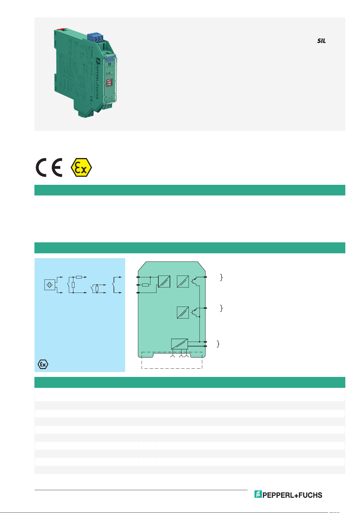
KFD2-ST2-Ex1-LB
Zone 2
Div. 2
Zone 0, 1, 2
Div. 1, 2
24 V DC
14+
15-
Power Rail
24 V DCERR
2+
3-
1+
7+
9+
I
II
10 kΩ
400 Ω ≤ R ≤ 2 kΩ
10 kΩ
Germany: +49 621 776 2222Pepperl+Fuchs Group
Refer to "General Notes Relating to Pepperl+Fuchs Product Information".
USA: +1 330 486 0002 Singapore: +65 6779 9091
www.pepperl-fuchs.com pa-info@us.pepperl-fuchs.com pa-info@sg.pepperl-fuchs.com
pa-info@de.pepperl-fuchs.com
KFD2-ST2-Ex1.LB
1-channel isolated barrier
<
24 V DC supply (Power Rail)
<
Dry contact or NAMUR inputs
<
Active transistor output
<
Active fault output
<
Line fault detection (LFD)
<
Reversible mode of operation
<
Up to SIL 2 acc. to IEC 61508
<
24 V DC
Function
This isolated barrier is used for intrinsic safety applications. It transfers digital signals (NAMUR sensors/mechanical contacts) from a hazardous
area to a safe area.
The proximity sensor or switch controls an active transistor output per channel for the safe area load. The normal output state is reversed using
switch S1. Switch S2 allows output II to be switched between a signal output and an error message output. Switch S3 enables or disables line fault
detection of the field circuit.
During an error condition, the transistors revert to their de-energized state and LEDs indicate the fault according to NAMUR NE44.
A unique collective error messaging feature is available when used with the Power Rail system.
Connection
Technical Data
General specifications
Signal type Digital Input
Functional safety related parameters
Safety Integrity Level (SIL) SIL 2
Supply
Connection Power Rail or terminals 14+, 15Rated voltage U
Ripple ≤ 10 %
Rated current I
Input
Release date: 2020-09-23 Date of issue: 2020-09-23 Filename: 180997_eng.pdf
r
r
20 ... 30 V DC
≤ 50 mA
1
Page 2
Switch Amplifier KFD2-ST2-Ex1.LB
Germany: +49 621 776 2222Pepperl+Fuchs Group
Refer to "General Notes Relating to Pepperl+Fuchs Product Information".
USA: +1 330 486 0002 Singapore: +65 6779 9091
www.pepperl-fuchs.com pa-info@us.pepperl-fuchs.com pa-info@sg.pepperl-fuchs.com
pa-info@de.pepperl-fuchs.com
Technical Data
Connection side field side
Connection terminals 1+, 2+, 3Rated values acc. to EN 60947-5-6 (NAMUR), see system description for electrical data
Open circuit voltage/short-circuit current approx. 8 V DC / approx. 8 mA
Switching point/switching hysteresis 1.2 ... 2.1 mA / approx. 0.2 mA
Line fault detection breakage I ≤ 0.1 mA , short-circuit I > 6 mA
Output
Connection side control side
Connection output I: terminals 7+ ; output II: terminals 9+
Signal level 1-signal: (L+) - 3.5 V (100 mA, short-circuit protected)
Output I signal , electronic output, active
Output II signal or error message , electronic output, active
Collective error message Power Rail
Transfer characteristics
Switching frequency ≤ 5 kHz
Galvanic isolation
Input/Output reinforced insulation acc. to IEC 62103, rated insulation voltage 300 V
Input/power supply reinforced insulation acc. to IEC 62103, rated insulation voltage 300 V
Output/power supply not available , common pole terminal 14+
Output/Output not available , common pole terminal 14+
Indicators/settings
Display elements LEDs
Control elements DIP-switch
Configuration via DIP switches
Labeling space for labeling at the front
Directive conformity
Electromagnetic compatibility
Directive 2014/30/EU EN 61326-1:2013 (industrial locations)
Conformity
Galvanic isolation IEC 62103:2003
Electromagnetic compatibility NE 21:2004
Degree of protection IEC 60529:2001
Input EN 60947-5-6:2000
Ambient conditions
Ambient temperature -20 ... 60 °C (-4 ... 140 °F)
Mechanical specifications
Degree of protection IP20
Connection screw terminals
Mass approx. 150 g
Dimensions 20 x 119 x 115 mm (0.8 x 4.7 x 4.5 inch) , housing type B2
Mounting on 35 mm DIN mounting rail acc. to EN 60715:2001
Data for application in connection with hazardous areas
EU-Type Examination Certificate PTB 00 ATEX 2035
Marking 1 II (1) G [Ex ia] IIC
Input Ex ia IIC, Ex ia IIIC
Voltage U
Current I
Power P
Supply
Maximum safe voltage U
Output
Maximum safe voltage U
Release date: 2020-09-23 Date of issue: 2020-09-23 Filename: 180997_eng.pdf
0-signal: switched off (off-state current ≤ 10 µA)
1 II (1) D [Ex ia] IIIC
10.5 V
o
13 mA
o
34 mW (linear characteristic)
o
40 V DC (Attention! The rated voltage can be lower.)
m
40 V DC (Attention! The rated voltage can be lower.)
m
rms
rms
2
Page 3

1
3
4
6
2
5
13 15
12
9
10
7
14
11
8
KFD2-ST2-Ex1.LB
OUT CHK PWR
S2
S1
S3
III
Front view
LED red:
LB/SC
LED green:
Power supply
Switch S2
(output selection II)
Removable terminals
green
Removable terminal
blue
Switch S1
(mode of operation)
Switch S3
(LB/SC-monitoring)
LED yellow:
Transistor output
Switch Amplifier KFD2-ST2-Ex1.LB
Germany: +49 621 776 2222Pepperl+Fuchs Group
Refer to "General Notes Relating to Pepperl+Fuchs Product Information".
USA: +1 330 486 0002 Singapore: +65 6779 9091
www.pepperl-fuchs.com pa-info@us.pepperl-fuchs.com pa-info@sg.pepperl-fuchs.com
pa-info@de.pepperl-fuchs.com
Technical Data
Certificate TÜV 99 ATEX 1499 X
Marking 1 II 3G Ex nA II T4
Galvanic isolation
Input/Output safe electrical isolation acc. to IEC/EN 60079-11, voltage peak value 375 V
Input/power supply safe electrical isolation acc. to IEC/EN 60079-11, voltage peak value 375 V
Directive conformity
Directive 2014/34/EU EN 60079-0:2012+A11:2013 , EN 60079-11:2012 , EN 60079-15:2010 , EN
International approvals
FM approval
Control drawing 116-0035
CSA approval
Control drawing 116-0047
IECEx approval
IECEx certificate IECEx PTB 05.0011
IECEx marking [Ex ia] IIC , [Ex ia] I , [Ex ia] IIIC
General information
Supplementary information Observe the certificates, declarations of conformity, instruction manuals, and manuals
Accessories
Optional accessories - power feed module KFD2-EB2(.R4A.B)(.SP)
50303:2000
where applicable. For information see www.pepperl-fuchs.com.
- universal power rail UPR-03(-M)(-S)
- profile rail K-DUCT-BU(-UPR-03)
Assembly
Accessories
KFD2-EB2 Power Feed Module
Release date: 2020-09-23 Date of issue: 2020-09-23 Filename: 180997_eng.pdf
3
Page 4

Switch Amplifier KFD2-ST2-Ex1.LB
Germany: +49 621 776 2222Pepperl+Fuchs Group
Refer to "General Notes Relating to Pepperl+Fuchs Product Information".
USA: +1 330 486 0002 Singapore: +65 6779 9091
www.pepperl-fuchs.com pa-info@us.pepperl-fuchs.com pa-info@sg.pepperl-fuchs.com
pa-info@de.pepperl-fuchs.com
Accessories
KFD2-EB2.R4A.B Power feed module, redundant supply
KFD2-EB2.R4A.B.SP Power feed module with spring terminals, redundant supply
KFD2-EB2.SP Power feed module with spring terminals
UPR-03 Universal Power Rail with end caps and cover, 3 conductors, length: 2 m
UPR-03-M Universal Power Rail with end caps and cover, 3 conductors, length: 1,6 m
UPR-03-S Universal Power Rail with end caps and cover, 3 conductors, length: 0.8 m
K-DUCT-BU
K-DUCT-BU-UPR-03 Profile rail with UPR-03- * insert, 3 conductors, wiring comb field side blue
Release date: 2020-09-23 Date of issue: 2020-09-23 Filename: 180997_eng.pdf
4
Page 5

Germany: +49 621 776 2222Pepperl+Fuchs Group
Refer to "General Notes Relating to Pepperl+Fuchs Product Information".
USA: +1 330 486 0002 Singapore: +65 6779 9091
www.pepperl-fuchs.com pa-info@us.pepperl-fuchs.com pa-info@sg.pepperl-fuchs.com
pa-info@de.pepperl-fuchs.com
Switch Amplifier
789
10 11 12
123
456
13 14 15
1
PWRCHKOUT
S1
S2
S3
123
123
S1
S3
IIS2I
Configuration
KFD2-ST2-Ex1.LB
Switch position
SFunction Position
1 Mode of operation output I active with high input current I
with low input current II
2 Assignment output II Switching state like output I I
Fault indication output (passive if fault) II
3 Line fault detection ON I
OFF II
Operating states
Control circuit Input signal
Initiator high impedance/contact opened low input current
Initiator low impedance/contact closed high input current
Lead breakage, lead short circuit Line fault
Factory setting: switch 1, 2 and 3 in position I
Release date: 2020-09-23 Date of issue: 2020-09-23 Filename: 180997_eng.pdf
5
 Loading...