

Page 1
Solenoid Driver
2
Zone 2
Div. 2
Zone 0, 1, 2
Div. 1, 2
KFD2-SL2-Ex1.LK
2-
3-
1+
7
8 (+/-)
24 V DC
14+
15-
Power Rail
24 V DCERR
ERR
10
11
12
V
Germany: +49 621 776 2222Pepperl+Fuchs Group
Refer to "General Notes Relating to Pepperl+Fuchs Product Information".
USA: +1 330 486 0002 Singapore: +65 6779 9091
www.pepperl-fuchs.com pa-info@us.pepperl-fuchs.com pa-info@sg.pepperl-fuchs.com
pa-info@de.pepperl-fuchs.com
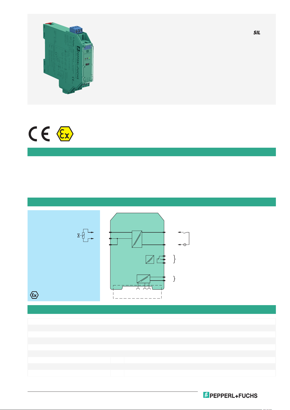
KFD2-SL2-Ex1.LK-Y1
1-channel isolated barrier
<
24 V DC supply (Power Rail)
<
Increased input load
<
Output 45 mA at 11.2 V DC
<
Logic input, non-polarized
<
Fault indication output
<
Line fault detection (LFD)
<
Up to SIL 2 acc. to IEC 61508
<
Function
This isolated barrier is used for intrinsic safety applications.
The device supplies power to solenoids, LEDs and audible alarms located in a hazardous area.
It is controlled via a logic signal. The input has two defined states: 1-Signal = 16 V DC ... 30 V DC, 0-Signal = 0 V DC ... 5 V DC. The current
consumption of the input is about 3 mA.
At full load, 11.2 V at 45 mA is available for the hazardous area application.
If the field impedance is > 10 kΩ for lead breakage or < 50 Ω for short circuits a line fault is detected.
During an error condition, the fault indication output de-energizes.
A fault is signalized by LEDs and a separate collective error message output.
Connection
Technical Data
General specifications
Signal type Digital Output
Functional safety related parameters
Safety Integrity Level (SIL) SIL 2
Supply
Connection Power Rail or terminals 14+, 15Rated voltage U
Power dissipation max. 1.5 W
Power consumption max. 2 W at 45 mA output current
Release date: 2020-09-23 Date of issue: 2020-09-23 Filename: 808102_eng.pdf
r
19 ... 30 V DC
1
Page 2
Solenoid Driver KFD2-SL2-Ex1.LK-Y1
Germany: +49 621 776 2222Pepperl+Fuchs Group
Refer to "General Notes Relating to Pepperl+Fuchs Product Information".
USA: +1 330 486 0002 Singapore: +65 6779 9091
www.pepperl-fuchs.com pa-info@us.pepperl-fuchs.com pa-info@sg.pepperl-fuchs.com
pa-info@de.pepperl-fuchs.com
Technical Data
Input
Connection side control side
Connection terminals 7, 8
Input current 1-signal: 3.5 mA over the entire range
Signal level 1-signal: 16 ... 30 V DC
Output
Connection side field side
Output I
Connection terminals 1+, 2- or 3Internal resistor Ri270 Ω
Current I
Voltage Uemin. 11.2 V
Open loop voltage Usmin. 23.5 V
Output signal These values are valid for the rated operating voltage 19 ... 30 V DC.
Energized/De-energized delay ≤ 20 ms / ≤ 20 ms
Line fault detection signal at short-circuit RB < 50 Ω, lead breakage RB > 10 kΩ ; test current < 650 µA
Output II fault signal
Connection terminals 10, 11, 12 , non-intrinsically safe
Contact loading 253 V AC/2 A/cos φ > 0.7; 40 V DC/2 A resistive load
Mechanical life 2 x 10⁷ switching cycles
Energized/De-energized delay ≤ 20 ms / ≤ 20 ms
Galvanic isolation
Input/power supply basic insulation according to IEC/EN 61010-1, rated insulation voltage 50 V
Output I, II against eachother reinforced insulation according to IEC/EN 61010-1, rated insulation voltage 300 V
Output II/power supply reinforced insulation according to IEC/EN 61010-1, rated insulation voltage 300 V
Indicators/settings
Display elements LEDs
Control elements DIP-switch
Configuration via DIP switches
Labeling space for labeling at the front
Directive conformity
Electromagnetic compatibility
Directive 2014/30/EU EN 61326-1:2013 (industrial locations)
Low voltage
Directive 2014/35/EU EN 61010-1:2010
Conformity
Electromagnetic compatibility NE 21:2007
Degree of protection IEC 60529:2001
Ambient conditions
Ambient temperature -20 ... 60 °C (-4 ... 140 °F)
Mechanical specifications
Degree of protection IP20
Connection screw terminals
Mass approx. 150 g
Dimensions 20 x 119 x 115 mm (0.8 x 4.7 x 4.5 inch) , housing type B2
Mounting on 35 mm DIN mounting rail acc. to EN 60715:2001
Data for application in connection with hazardous areas
EU-Type Examination Certificate ZELM 99 ATEX 0015
Marking 1 II (1)G [Ex ia Ga] IIC
Output I Ex ia
Release date: 2020-09-23 Date of issue: 2020-09-23 Filename: 808102_eng.pdf
0-signal: 1.5 mA at 5 V DC
0-signal: 0 ... 5 V DC
max. 45 mA
e
1 II (1)D [Ex ia Da] IIIC
1 I (M1) [Ex ia Ma] I
eff
eff
eff
2
Page 3

Solenoid Driver KFD2-SL2-Ex1.LK-Y1
Germany: +49 621 776 2222Pepperl+Fuchs Group
Refer to "General Notes Relating to Pepperl+Fuchs Product Information".
USA: +1 330 486 0002 Singapore: +65 6779 9091
www.pepperl-fuchs.com pa-info@us.pepperl-fuchs.com pa-info@sg.pepperl-fuchs.com
pa-info@de.pepperl-fuchs.com
Technical Data
Voltage U
Current I
Power P
28 V
o
110 mA
o
770 mW (linear characteristic)
o
Supply
Maximum safe voltage U
40 V (Attention! The rated voltage can be lower.)
m
Input
Maximum safe voltage U
60 V (Attention! The rated voltage can be lower.)
m
Collective error message
Maximum safe voltage U
40 V (Attention! The rated voltage can be lower.)
m
Certificate TÜV 02 ATEX 1820 X
Marking 1 II 3G Ex nA nC IIC T4 Gc
Output II
Contact loading 50 V AC/2 A/cos φ > 0.7; 40 V DC/2 A resistive load
Galvanic isolation
Output I/other circuits safe electrical isolation acc. to IEC/EN 60079-11, voltage peak value 375 V
Directive conformity
Directive 2014/34/EU EN 60079-0:2012+A11:2013 , EN 60079-11:2012 , EN 60079-15:2010 , EN
60079-26:2007 , EN 50303:2000
International approvals
CSA approval
Control drawing 116-0362
IECEx approval
IECEx certificate IECEx ZLM 14.0001
IECEx marking [Ex ia Ga] IIC, [Ex ia Da] IIIC, [Ex ia Ma] I
General information
Supplementary information Observe the certificates, declarations of conformity, instruction manuals, and manuals
where applicable. For information see www.pepperl-fuchs.com.
Accessories
Optional accessories - power feed module KFD2-EB2(.R4A.B)(.SP)
- universal power rail UPR-03(-M)(-S)
- profile rail K-DUCT-BU(-UPR-03)
Release date: 2020-09-23 Date of issue: 2020-09-23 Filename: 808102_eng.pdf
3
Page 4

1
3
4
6
2
5
13 15
12
9
10
7
14
11
8
KFD2-SL2-Ex1.LK
OUT CHK PWR
III
Front view
LED green:
Power supply
Removable terminals
green
LED yellow:
Status
LED red:
LB/SC
Removable terminal
blue
LB/SC
Position I: ON
Position II: OFF
Solenoid Driver KFD2-SL2-Ex1.LK-Y1
Germany: +49 621 776 2222Pepperl+Fuchs Group
Refer to "General Notes Relating to Pepperl+Fuchs Product Information".
USA: +1 330 486 0002 Singapore: +65 6779 9091
www.pepperl-fuchs.com pa-info@us.pepperl-fuchs.com pa-info@sg.pepperl-fuchs.com
pa-info@de.pepperl-fuchs.com
Assembly
Accessories
KFD2-EB2 Power Feed Module
KFD2-EB2.R4A.B Power feed module, redundant supply
KFD2-EB2.R4A.B.SP Power feed module with spring terminals, redundant supply
KFD2-EB2.SP Power feed module with spring terminals
UPR-03 Universal Power Rail with end caps and cover, 3 conductors, length: 2 m
UPR-03-M Universal Power Rail with end caps and cover, 3 conductors, length: 1,6 m
UPR-03-S Universal Power Rail with end caps and cover, 3 conductors, length: 0.8 m
K-DUCT-BU
K-DUCT-BU-UPR-03 Profile rail with UPR-03- * insert, 3 conductors, wiring comb field side blue
Release date: 2020-09-23 Date of issue: 2020-09-23 Filename: 808102_eng.pdf
4
Page 5

Germany: +49 621 776 2222Pepperl+Fuchs Group
Refer to "General Notes Relating to Pepperl+Fuchs Product Information".
USA: +1 330 486 0002 Singapore: +65 6779 9091
www.pepperl-fuchs.com pa-info@us.pepperl-fuchs.com pa-info@sg.pepperl-fuchs.com
pa-info@de.pepperl-fuchs.com
Solenoid Driver
R
i
U
s
U
U
s
U
e
I
e
I
Output circuit diagram Output characteristic
KFD2-SL2-Ex1.LK-Y1
Application
e. g. Yokogawa ProSafe DO card SDV541, SDV531 with deactivated test pulse and deactivated line fault detection
Characteristic Curve
Output characteristics
Release date: 2020-09-23 Date of issue: 2020-09-23 Filename: 808102_eng.pdf
5
 Loading...