

Page 1

Manual
BA268F/00/en 02.03 Part No. 52017696
KFD2-HMM-16
HART Multiplexer Master
PROCESS AUTOMATION
PEPPERL+FUCHS
Page 2

The general terms of delivery for products and services produced or provided by the electrical industry as
published by the Zentralverband Elektrotechnik und Elektroindu stri e (ZVEI) e.V.
in its most recent edition as well as the supplementary proviso: "Extended property proviso" are applicable.
We at Pepperl+Fuchs feel obligated to contribute to the future;
this publication is, therefore, printed on paper bleached without the use of chlorine.
Page 3

HART Multiplexer Master KFD2-HMM-16
Table of contents
Table of contents
1INTRODUCTION ....................................................................................................................5
1.1 Explanation of the symbols used in the manual ...................................... ................................................5
1.2 Aim of the manual .............................................................. ..........................................................................5
1.3 Intended use .................................................................................................................................................5
1.4 Responsibilities of the user ........................................................................................................................6
1.5 Marking .........................................................................................................................................................6
2PRODUCT DESCRIPTION .......................................................................................................7
2.1 HART multiplexer master .................. ................................................................ ..........................................7
2.1.1 Delivery package ....................................... ................................................................. ...................................7
2.1.2 Accessories/Product family ............................................................................................................................7
2.1.3 Description of the hardware ...........................................................................................................................7
2.1.4 Galvanic isolation ...........................................................................................................................................9
2.1.5 Cabling for the analogue signals ...................................................................................................................9
2.1.6 Device function ..............................................................................................................................................9
2.1.7 Start-up sequence ..... ...... ....... ................................................................ ....... ...... ........................................11
2.1.8 Operation .....................................................................................................................................................11
2.1.9 LED indicators .............................................................................................................................................12
2.1.10 Device parameter, parameterisation ....................................................... .................... ................... .............. 12
2.1.11 Connection to the service station (PC, DCS/Process control system) ........................................................13
2.1.12 DIP switch settings ......................................................................................................................................13
2.1.13 Co nne ction and Connection Assignment of RS 485 ................................................................ ...... ..... .........14
2.2 Description of the HART communication ........................ ...... ....... ...... ....... ...... ....... ...... ....... ...... ..............15
2.3 System construction ............................... ................................................................. .................................16
2.3.1 System description ......................................................................................................................................16
2.3.2 Service station .............................................................................................................................................16
2.3.3 Integration in the operating software (Asset Management Systems) ..........................................................16
2.3.4 System construction with and without mul ti ple xer slaves .............................................................. ..............17
2.3.5 System structure with Flex-interface solutions ............................................................................................18
2.3.6 Structure with motherboard solutions ..........................................................................................................19
2.4 HART Multiplexer Slave ....................................... .....................................................................................20
2.5 Slave connection .......................................................................................................................................20
3INSTALLATION ...................................................................................................................21
3.1 Storage and transportation .................................................................. ....... ...... ....... ...... ...........................21
3.2 Unpacking ..................................................................................................................................................21
3.3 Installation ...................... .......................................................... ..................................................................21
3.4 Electrical connection .................................................................................................................................21
3.4.1 General notes for connect ion ..................................................... ..................................................................21
3.4.2 Location of electrical connections ................................................................................................................21
3.4.3 Note on electromagnetic compatability (EMC) .................... ...... ................................................................. .22
3.5 Dismantling, packaging and disposal .....................................................................................................22
Part No.: 109143, Date of issue 29.11.2000
Subject to reasonable modifications due to technical advances. Copyright Pepperl+Fuchs, Printed in Germany
Pepperl+Fuchs Group • Tel.: Germany (06 21) 7 76-0 • USA (330) 4 25 35 55 • Singapore 7 79 90 91 • Internet http://www.pepperl-fuchs.com
3
Page 4

HART Multiplexer Master KFD2-HMM-16
Table of contents
4COMMISSIONING ...............................................................................................................23
4.1 Commissioning check list ........................................................................................................................ 23
4.2 Data access to the connected transmitters ......................................................... ...... ............................. 23
5DIAGNOSIS AND FAULT ELIMINATION ................................................................................. 24
5.1 General ................................ ................... ............. .................... ................... ................................................ 24
5.2 LEDs ............................. .................................................... .......................................................................... 24
5.3 Status/Response code (Response code) ...............................................................................................24
5.3.1 General .......................................................................................................................................................24
5.3.2 Structure of the first byte ............................................................................................................................. 24
5.3.3 Device status (structure of the second byte) ............................................................................................... 26
5.4 Extended device status ............................................................................................................................ 27
6APPENDIX .........................................................................................................................28
6.1 Supported commands .............................................................................................................................. 28
6.2 Terminal assignment of the 26 pin connector with analogue HART signals ...................................... 31
6.3 Literature ...................................................................................................................................................32
6.4 Glossary ....................... ............. .................... ................... ................... .................... ................................... 32
Part No.: 109143, Date of issue 29.11.2000
Subject to reasonable modifications due to technical advances. Copyright Pepperl+Fuchs, Printed in Germany
4
Pepperl+Fuchs Group • Tel.: Germany (06 21) 7 76-0 • USA (330) 4 25 35 55 • Singapore 7 79 90 91 • Internet http://www.pepperl-fuchs.com
Page 5
1 Introduction
1.1 Explanation of the symbols used in the manual
This symbol warns of danger. If the instruction given in this warning is not heeded the result
could be the injury or death of personnel and/or the severe damage or destruction of equipment.
This symbol advises of a possible failure. If the instructio n gi ven in this warni ng is not heeded,
the device and any plant or systems connected to it could develop a fault or even fail completely.
This symbol indicates important information.
HART Multiplexer Master KFD2-HMM-16
Introduction
1.2 Aim of the manual
This manual should enable the user to install the HART multiplexer master, to commission it and to maintain
it. It provides all the information required on status and fault messages and also provides a guide to fault
diagnosis and rectifi ca tio n.
In addition, the manual provides an introduction to HART communication. For additional information, the attention of the user is directed to the bibliography in the appendix and to other literature on the subject, including the pub li ca tions of the HART Communication Foundation
(www.hartcomm.org).
Where reference to the bibliography is made in this manual it is indicated thus: /3/.
The appendix also explains many terms and abbreviations used in this manual.
1.3 Intended use
The HART multiplexer master KFD2-HMM-16 provides full HART access to up to 256 field de vices and
hence operation with the conventional 4m A.. .2 0mA current loops. It thus acts as a transparent gateway
between the service station (PC, or proc es s co ntro l sy s tem ) and the trans mit ter s.
The multiplexer can be used within Zone 2 hazardous areas or in the safe area. Power is provided by a 24 V
(nominal voltage) DC power su ppl y . Connec ti on to the pr oc es s co ntr ol sys tem or PC is via an R S485
interface.
It should be stressed that the HART multiplexer master KFD2-HMM-16 is approved for use in
zone 2 and therefore may not be used in zone 0 or 1 hazardous areas. If the equipment is used
in conjunction with intrinsically safe or associated apparatus, then this use must take place in
front of the Ex-barrier (e. g. transmitter power supply device).
Reference should be made to the statement of conformity contained in TÜV 00 ATEX 1547 X.
Part No.: 109143, Date of issue 29.11.2000
Subject to reasonable modifications due to technical advances. Copyright Pepperl+Fuchs, Printed in Germany
Pepperl+Fuchs Group • Tel.: Germany (06 21) 7 76-0 • USA (330) 4 25 35 55 • Singapore 7 79 90 91 • Internet http://www.pepperl-fuchs.com
5
Page 6

1.4 Responsibilities of the user
In order to avoid damage, incorrect operation and equipment failures, the user must make himself acquainted with the equipment and must have read and understood the manual before undertaking i t s inst a llation and commissioning.
Repairs to the device must only be undertaken by spec ialist personnel and in compliance with
the relevant regulations.
We strongly recommend that repairs are undertaken by the manufacturer. No guarantee claims
will be accepted by Pepperl+Fuchs GmbH resulting from improper repair work.
1.5 Marking
The following identification is affixed to the KFD2-HMM-16 multiplexer:
Pepperl+Fuchs G mbH
D-68307 Mannheim
KFD2-HMM-16
HART Multiplexer Master KFD2-HMM-16
Introduction
TÜV 00 ATEX 1547 X II 3G EEx n A II T4
Part No.: 109143, Date of issue 29.11.2000
Subject to reasonable modifications due to technical advances. Copyright Pepperl+Fuchs, Printed in Germany
6
Pepperl+Fuchs Group • Tel.: Germany (06 21) 7 76-0 • USA (330) 4 25 35 55 • Singapore 7 79 90 91 • Internet http://www.pepperl-fuchs.com
Page 7

2 Product description
2.1 HART multiplexer master
2.1.1 Delivery package
Included in the delivery package of the devic e are:
• One device KFD2-HMM-16
• One product supplement (manual, data sheet, installation instruction)
2.1.2 Accessories/Product family
In addition to the HART multiplexer master, the following items from the HART multiplexer system family of
products are availab le from Pepperl+Fuchs:
• KFD0-HMS-16, HART multiplexer slave, for extending the HART channels
• KSD2-HC, HART RPI control module, for connecting the HART multiplexer to the RPI product family
• K-HM14, cable master ↔ slave, for connecting the master with the slaves
• FI-***, HART flexible interface, handover interface of the analogue signals between transmitter, multiple-
xer and PLC/DCS (control sys tem spe ci fi c)
• MB-***, motherboard, carrier board for Ex-isolator module
• K-HM26, cable master/slave ↔ FI-***/MB-***, for connection of master/slave with flexible interface FI-***
or motherboard MB-***, res pectively
• Interface converter RS 485 ↔ RS 232 (Telebyte Model No. 285), converter RS 485 ↔ RS 232,
Pepperl+Fuchs o rd e r code: Telebyte Model 285M
HART Multiplexer Master KFD2-HMM-16
Product description
The complete product family is described in the Pepperl+Fuchs p ro duc t catalogues.
Please refer to the ordering instructions detailed in the catalogues.
2.1.3 Description of the hardware
The HART multiplexer can operate up to 256 analogue transmitters. The built-in slave unit operates the first
16 loops, and a maximum of a further 15 KFD0-HMS-16 slaves can be connected.
The external connections are shown in Fi gu re 2.1 and Figure 2.2.
The power supply (2 4 VDC nominal voltage) is provided via the power rail or terminals 17 and18. The op-
tional slave units or the RPI control module are connected with the master via a 14-core flat cable (K-HM14).
Its connector is placed on the same housing side as the terminals for the R S485 interface and the voltage
supply. The analogue signals for each unit are connected separately via a 26-core cable. 16 leads are provided for the HART signals of the analogue instrument circuits, the other 10 are connected to ground. The
minimum load resistance of the analogue instrument circuits is 2 30Ω (min. load resistance in accordance
with the HART specification), the max. load resistance is 5 0 0Ω. Load resistances of up to 1000 Ω are pos-
sible, however, resistance values greater than 500 Ω can interfer e with the HA RT communi cation. The connector for these conn ectio ns i s locat ed on th e top of the housing. A proces s control sys tem or a PC ca n be
connected via a RS485 interface (terminals 13, 14 and 15). Up to 31 KFD2-HMM-16 can be operated on
one RS 485 interface. Terminals 19, 20 and 21 can be used to connect additional stations to the R S485
interface. The DIP-switch on the housing front is for the setting of the R S485 address and the baud rate.
Part No.: 109143, Date of issue 29.11.2000
Subject to reasonable modifications due to technical advances. Copyright Pepperl+Fuchs, Printed in Germany
Pepperl+Fuchs Group • Tel.: Germany (06 21) 7 76-0 • USA (330) 4 25 35 55 • Singapore 7 79 90 91 • Internet http://www.pepperl-fuchs.com
7
Page 8
HART Multiplexer Master KFD2-HMM-16
Product description
13 14 15 19 20 21
grd T- T+
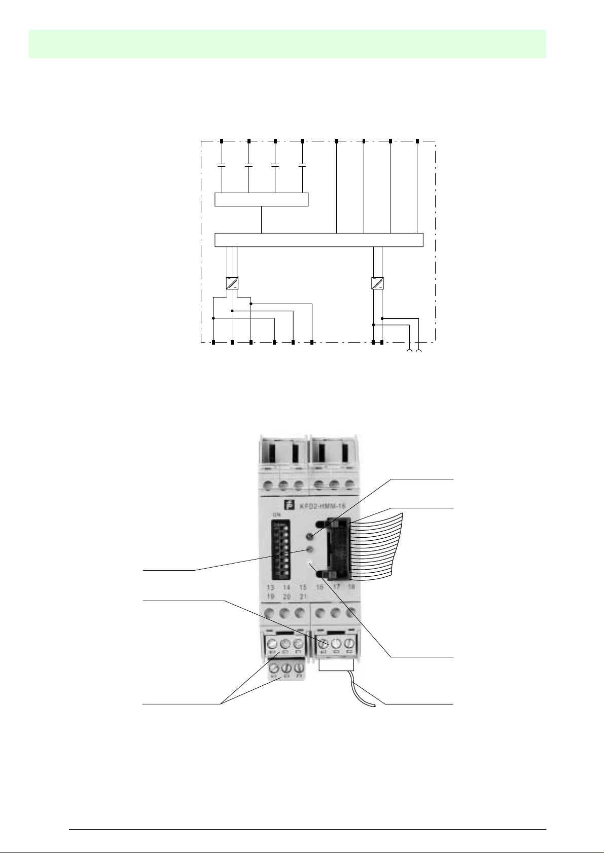
Figure 2.1: Block diagramm KFD2-HMM-16
26 pin connector
for up to
16 analog signal sources
Multiplexer
RS 485
Repeater
Micro processor
14 pin connector
for up to
15 KFD0-HMS-16 devices
+ -
17+ 18-
Power supply
Power Rail
Front view
LED red:
Fault signal
26 pin connector
1
LED green:
Power supply
26
Power supply
LED orange:
operational
Connectors RS 485
14 pin connector
Figure 2.2: Location of the plug connectors and controls and the indicators of the KFD2-HMM-16
Part No.: 109143, Date of issue 29.11.2000
Subject to reasonable modifications due to technical advances. Copyright Pepperl+Fuchs, Printed in Germany
8
Pepperl+Fuchs Group • Tel.: Germany (06 21) 7 76-0 • USA (330) 4 25 35 55 • Singapore 7 79 90 91 • Internet http://www.pepperl-fuchs.com
Page 9
2.1.4 Galvanic isolation
The voltage supply, the analogue signals and the RS 485 interface are galvanically separated. This galvanic
isolation is achieved through the use of transformers and opto couplers.
For the direct current components, the individual HART channels are isolated by means of capacitors. Thus
the 4 mA ... 20 mA signal is not affected .
The connected current repeaters are galvanically interconnected unilaterally through the common ground connection of the analogue signals.
If the galvanic isolation is to be properly maintained, the individual ground cables must be isolated by capacitors. Suitable Fl and MB boards can be supplied by Pepperl+Fuchs for this purpose.
Notwithstanding the common ground connection of the analogue signals from the masters/slaves, the galvanic isolation of t he cur r ent repeaters is secured if
• FI and MB boards are used, whic h a re fitted with capacitors.
• KFD2-STC4-Ex1 or KFD2-STC4-Ex2 Ex isolation modules are used as current repeaters.
2.1.5 Cabling for the analogue signals
The individual I/O components of the HART product family are connected by a single 26-pin system plug
connector for the connecti on of the individual current repeaters (for plug pin assignmentsee section 6.2).
Pepperl+Fuchs provide specially developed connector units (HART interfaces type FI-***) for this purpose.
As required, the connection to these units can be via a system cable or even by means of conventional
screwconnections. If the current repeaters are mounted on a motherboard (MB-***), the connection is made
directly from the board to the multiplexer via a flat cable type K-HM26.
The control system is conne cte d via a s yste m spe cif ic connecto r of the motherboard or the Flex-interface.
Flex-interfaces with screw terminals are available for the purpose of individual wiring.
HART Multiplexer Master KFD2-HMM-16
Product description
2.1.6 Device function
The software functions described in this section are normally integrated into the operating software for the servicing station, i.e. the functions are not generally (de- ) ac ti vated via the des c ribed HART commands. In contrast the operating software uses func ti on s (menu command s) to
control these procedures. However the basic HART commands are described as well, because
the functions may be named different in the various operating softwares and the basic function
may not be obvious. Information on the supported commands can be found in section 6.1.
Channel number
The HART multiplexer master KFD2-HMM-16 provides 16 channels for the connection of "smart“ transmitters or control devices, which support digital communication in accordance with the HART specification. A
maximum of 15 additional KFD0-HMS-16 slaves can be connected, each of which in turn support 16 channels. Thus in a full assembly, a loop of 256 channels can be achieved with just one master. When using the
multiplexer master with the RPI product family, no slave units are necessary. On RPI, communication takes
place via the power rail.
Multiplexer table (module table)
The multiplexer master and the connected multiplexer slaves must be designated as 'available' in a multiplexer table (command 157). Only those modules defined as 'available' in this table are used in the communication process. The multiplexer table consists of 16 bit, one for each possible multiplexer address
(default: module 0 (master) and 1 activa ted).
Part No.: 109143, Date of issue 29.11.2000
Subject to reasonable modifications due to technical advances. Copyright Pepperl+Fuchs, Printed in Germany
Pepperl+Fuchs Group • Tel.: Germany (06 21) 7 76-0 • USA (330) 4 25 35 55 • Singapore 7 79 90 91 • Internet http://www.pepperl-fuchs.com
9
Page 10

HART Multiplexer Master KFD2-HMM-16
Product description
Interface
In this way, the multiplex er ma ste r act s as a transpa r ent gate way between the service station (typically a
PC with suitable software, see section 2.3.2) and the field devices. The service station is able to communicate with up to 31 multiplexer master via up to 38400 baud R S485 connection. Because each master is
able to communicate with 256 field devices, up to 7936 field devices are controlable over a singl e RS485
interface.
HART
As a digital communication system for servicing and configuration purposes, the HART protocol is supported by many field devices with conventional analogu e 4m A. . .2 0mA current loops. The HART signal is
thus modulated on the analogue current as an FSK signal (see se cti on 2.2). The modulator/demodulator
circuitry (Modem) required for this is integrated in the multiplexer. Only one HART transmitter can be connected at each multiple xe r HART con necti on (n o "multidrop“ functionality).
Special procedures in respect to HART commun i cation:
• On the host side (RS 485) always the long frame address is used (except for command 0).
• On the field devices side, either the sho rt address or the long frame address is used, depending on
necessity.
• The operating modes "Primary Master“ and "Secondary Master" and the corresponding time responses
are supported on the field device side.
• On the host side, only the commands 0 ... 3 and 1 1. . .13 are accepted from the secondary h o st. Other
commands are not accepted/are ignored.
• Commands to connected field devices are only accepted by the primary host.
• Extended messages and messages in the Burst Mode are recognised and used, but not generated by
the multiplexer itself.
• An answer buffer is available for a delayed message response. This can be used to intermediately store
a message, the command for whic h req uir es a long execution time.
Loop construction/REBUILD (Software function)
On power-up, the device searches the multiplexers in the multiplexer table for the connected HART field
devices (commands 0 a nd 4
1
) and generates the internally required access tables. This function can also
be carried out by the connected service station, as is necessary, for example, in communication with newly
connected HART field devices. The duration of this function depends on the number of connected multiplexer slaves and HART field devices and also on the type of loop search (see command 153) and the permissible number of message repeats. With 16 HART devices (e.g. by using only one master without slaves) the
duration is between 1 5s and 3 0s. The number of permissible message repeats is set to "2" in the factory
setting and the loop search type to "single analogue".
During the REBUILD phase, only certain read commands are accepted from the service station (commands
0, 1, 2, 3, 11, 12, 13, 48, and 129). All other commands are followed by the response "Busy" (Code 32, see
section 5.3.2), until the REBUILD phase ends.
Cyclic data interrogation/SCAN (software function)
The multiplexer can read cyclic data from up to 31 transmitters. In this case th e SCAN option must be set
for the transmitter (command 137) and the SCAN function activated in the multiplexer (command 149,
function 1). Which data is transferred is determined by the "SCAN command" option (command 147).
If the SCAN function is activated, the transmitters, on which the SCAN option is activated are regularly chekked for data. In this case, the SCAN command is executed, with which one or more variables are read from
the transmitter. If a fiel d device does not res pond, it is designate d as having "disappeared" (see command
129), but it remains in the search list (i. e., it is searched for again on the next run sequence). If a device
has disappeared, but responds correctly on the next search command, it is then listed as "appeared". If,
instead of this, another device has answered, then the status "mismatched" is assigned.
10
1. Command 4 is additionally used on transmitters which only support the old HART specifications up to 4.
Subject to reasonable modifications due to technical advances. Copyright Pepperl+Fuchs, Printed in Germany
Pepperl+Fuchs Group • Tel.: Germany (06 21) 7 76-0 • USA (330) 4 25 35 55 • Singapore 7 79 90 91 • Internet http://www.pepperl-fuchs.com
Part No.: 109143, Date of issue 29.11.2000
Page 11

HART Multiplexer Master KFD2-HMM-16
Product description
Variation on the SCAN function (special SCAN function)
The multiplexer offers in addition a second SCAN function. With this special SCAN function (command 149,
function 2) an additional parameter is used, which defines the minimum length of the expected number of
data bytes. This can be different for each current loop, but must be set for each current loop that is to be
scanned.
The SCAN function itself takes place as above, however, the response of the transmitter is compared with
the expected data length. If the length of the response is less than the set minimum data length, the answer
is rejected. If the minimum length is 0, the answer is always saved.
Delay on channel change/Loop switch delay (software function when used with RPI)
If the HART multiplexer is used with the RPI HART control module KSD2-HC, a pause time must be inserted
when the multiplexer channel is changed. This pause time is necessary, since the RPI HART control module
has to monitor the communication channel of the multiplexer and recognise the channel change. This pause
time can be set by means of command 161.
All the functions at a glance
The following list gives all the functions once again at a glance:
• 16 channels, extendable to 256 channels by the connection of up to 15 KFD0- HMS- 16 slaves.
• Up to 7936 loops per interface
• Automatic search of all existing HART field devices (REBUILD)
• Facility for self-standing cyclic interrogation of the HART variables (SCAN)
• Acts as a primary or sec ondary master
• Fast RS 485 interface (multidrop) with up to 38400 baud
• Integrated Modem
• Removable terminals
• Supply via power rail
• Approval for zone 2
2.1.7 Start-up sequence
Following connection of the power supply, the device executes an initialisation procedure with self test. The
function is indicated by a flashing green LED, any errors detected are indicated by a red LED. Next a search
is made of the multiplexers in the multiplexer table (command 157) for available HART compatible field
devices (REBUILD). This function is indicated by a flashing orange LED. The REBUILD function can also
be started via the service station, e. g. in order to include connected transmitters in the communication
process during the operating phase. The duration of this function is dependent on the number of connected
transmitters, multiplexer slav es and message repeats in the case of errors, or if an interroga tio n has not
been answered. The factory setting for the number of repeats is "2". The search duration for this lies
between approx. 30 s and several minutes (full structure).
In addition, transient data are set to their pre-setting. Non-volatile stored data are retained. see section
2.1.10.
2.1.8 Operation
The multiplexer master KFD2 -HM M-16 al so func ti ons as a HART device (see also section 2.1.10). However, due to the incorporation into the operating software of the service station (see section 2.3.3), this
remains concealed from the user. The HART commands that are supported by the multiplexer can be found
in section 6.1.
For HART communication with the transmitters, the commands of the service station are passed through
without modifications.
Part No.: 109143, Date of issue 29.11.2000
Subject to reasonable modifications due to technical advances. Copyright Pepperl+Fuchs, Printed in Germany
Pepperl+Fuchs Group • Tel.: Germany (06 21) 7 76-0 • USA (330) 4 25 35 55 • Singapore 7 79 90 91 • Internet http://www.pepperl-fuchs.com
11
Page 12

2.1.9 LED indicators
The device has three LEDs, located on the front of the housing.
The meaning of these LEDs is given in the following table:
Colour Meaning
Red Error indications (detected during the initialisation phase)
Green Operating indications
Orange HART communication with a field device
During the initialisation phase, the green LED flashes, the other two are off.
During the REBUILD function, the green LED is ON and the orange flashes.
If all three LEDs flash one after the other, the DIP switch 1 (test) is in the "ON" position. Set the
switch to "OFF“ and repeat the commissioning.
2.1.10 Device parameter, parameterisation
For the identification and programming of the multiplexer master, this contains - as do other HART field
devices - specific parameters that are in the non-volatile memory. The following list shows these parameters
and how the programming must be carried out.
• Unambiguous device identification (see commands 0, 11)
The device identification provides information about the device (type, type-ID, serial number and revision
numbers) and the manufacturer and cannot be changed.
• Message (see commands 12 and 17)
An arbitrary 32 char ac ter long item of text can be stored in the device under this param ete r.
• Tag, description and date (see commands 13 and 18)
A tag (8 characters), description (16 characters) and a date, can be saved under these parameters.
• The number of preambles in message responses (see command 59)
This parameter is used to establish how many preambles are inserted in message responses. The presetting is 4, the setting range is 2 ... 20.
• Number of message repeats (retry) (see commands 144 and 145)
The number of message repeats can be separately set for the repeats in the case of communication
errors and for the response code "Busy" (see section 5.3.2).
The range of adjustment is 0.. .11 repeats. In the cas e of commun i cation errors, the pre-setting is 2, in
the case of the response code "Busy" it is 0.
• SCAN command (see section 2.1.6 and commands 146 and 147)
Of the available SCAN parameters, only the SCAN command is stored by non-volatile means. It signifies
which HART command (1, 2 or 3) is to be sent to the transmitter as the SCAN command.
• Master type (primary or secondary master) (see command 151)
This controls the priority for access to the HART field devices. A primary master always initiates a connection with a field device. A secondary master initiates a connection to a field device through an arbitration function (i.e. only when the primary master does not achieve access). The pre-setting of the
multiplexer is "Primary Master". A typical example of a secondary master is a hand-held operatin g
device.
• Loop type search (command 153)
At present, the multiplexer does not support a multidrop with HART, i. e. only one HART field device is
connected to each HART channel. With loop construction (REBUILD, see above )the connected field
devices are either always searched on the short address 0 ("single analogue"), or, in preparation for
multidrop, on the sh ort add ress es 0 ... 15, in which the first one found is addres sed (" si ngl e unk nown ").
• Module table (see section 2.1.6 and command 157)
• Delay time on channel change (loop-switch delay) (see section 2.1.6 and command 161)
HART Multiplexer Master KFD2-HMM-16
Product description
12
Part No.: 109143, Date of issue 29.11.2000
Subject to reasonable modifications due to technical advances. Copyright Pepperl+Fuchs, Printed in Germany
Pepperl+Fuchs Group • Tel.: Germany (06 21) 7 76-0 • USA (330) 4 25 35 55 • Singapore 7 79 90 91 • Internet http://www.pepperl-fuchs.com
Page 13

HART Multiplexer Master KFD2-HMM-16
2.1.11 Connection to the service st ation (PC, DCS/Process cont rol system)
The connection to the service station or to the control system is made via a multidrop able RS 485 interface.
The baud rate of this interface can be set to 9600, 19200 or 38400 baud via the DIP switches 2 and 3 (see
section 2.1.12). The device address for the communication via RS 485 is set by the DIP switches 4 to 8 (see
section 2.1.12).
When setting the address, care should be taken to ensure that no address is assigned more
than once, since this can lead to com mu nic ati on er ro rs or even communication failure.
The adjusted baud rate must comply with the service station.
2.1.12 DIP switch settings
8 DIP switches are located on the top of the device. DIP switch 1 is used by the manufacturer for testing the
device and must therefore always be set to "OFF".
DIP sw i tch 1 Meaning
Setting
OFF Normal st atus ( LED test de-activated)
ON LED test activated; all three LEDs flash one afte r the other
Product description
DIP switches 2 and 3 determine the baud rate of the RS 485 interface.
DIP sw i tch 2 3 Meaning
OFF OFF 9600 Baud
Setting
OFF ON 19200 Baud
ON OFF 38400 Baud
ON ON Not permitted
DIP switches 4 to 8 determine the RS485 address. A value is assigned to each of the individual DIP
switches for this purpose. The resulting address is given by the addition of the set values.
DIP sw i tch 4 5 6 7 8 Meaning
ON Value 16
ON Value 8
Setting
ON Value 4
ON Value 2
ON Value 1
Example: OFF ON ON OFF ON address = 8 + 4 + 1 = 13
To accep t the values set on the DIP switches, the device must be isolated briefly from power
supply.
Condition on delivery
DIP sw i tch 1 2 3 4 5 6 7 8 Meaning
Manufacturer te st d e- activat e d
Setting OFF OFF OFF OFF OFF OFF OFF OFF
Baud rate 9600 baud
RS 485 ad dr es s 0
The address 0 is set on the device when delivered. Care should be taken that no address is
assigned more than once.
Part No.: 109143, Date of issue 29.11.2000
Subject to reasonable modifications due to technical advances. Copyright Pepperl+Fuchs, Printed in Germany
Pepperl+Fuchs Group • Tel.: Germany (06 21) 7 76-0 • USA (330) 4 25 35 55 • Singapore 7 79 90 91 • Internet http://www.pepperl-fuchs.com
13
Page 14

2.1.13 Connection and Connection Assignment of RS 485
Connector assignment of the removable terminals:
Terminal Description Meaning
13, 19 Screen Cable screening
HART Multiplexer Master KFD2-HMM-16
Product description
14, 20 RxD/TxD + (RS 485 B)
RS 485 differential signal
15, 21 RxD/TxD - (R S485 A)
If the screen is grounded, the grounding should only be connected to one end of the cable, in
order to avoid equipotential bonding currents. However, in all cases, existing guidelines and
regulati ons must be observed.
To conne ct a s tand ard PC with a R S232 interface an interface converter R S485 to R S232 is
required. A convert er that has b een tes ted and re co mmended by Pep perl+Fuchs is manufactured by Telebyte (Telebyte Model No. 285). This can be obtained from Pepperl+Fuchs under the
part number "Telebyte Model 285M“.
In accordance with the RS 485 specification up to 32 stations ("multidrop") can be connected to a up to
1200 m cable (for data rates less than 100 kBaud). Pepperl+Fuchs recommends that this length of cable is
not exceeded. Even though problems seldom occur at these data rates, screened twisted two-wire cabling
should be used.
In addition a terminating resistor should be connected to each end of the R S485 cable. If the multiplexer
master is such a device, i. e. the RS 485 cable ends here and is not routed to other devices, then the second
available connection terminal for the RS 485 can be used for the connection of a terminating resistance.
The terminating resistor terminates the cables with its characteristic impedance. At minimal baud rates and
with short lengths of cable, in practice quite often no terminating resistors are used. If communication errors
arise, or if these are to be positively excluded from the outset, terminating resistors typically of
120 Ω ... 220 Ω should be used. Such can, for example, be connected between terminals 20 and 21.
If an interface converter is used, a terminating r es istor shou ld be con nec ted to the conver ter
and another to the other end of the cable.
14
Part No.: 109143, Date of issue 29.11.2000
Subject to reasonable modifications due to technical advances. Copyright Pepperl+Fuchs, Printed in Germany
Pepperl+Fuchs Group • Tel.: Germany (06 21) 7 76-0 • USA (330) 4 25 35 55 • Singapore 7 79 90 91 • Internet http://www.pepperl-fuchs.com
Page 15

2.2 Description of the HART communication
HART Multiplexer Master KFD2-HMM-16
Product description
The HART
1
protocol is supported by many conventional 4 mA ... 20 mA field devices, which thus enable
digital communication for configuration and servicing purposes. Many device parameters and also the measured values themselves can thus be digitally transferred to and from the device. This digital communication
runs in parallel with t h e 4m A. . .2 0mA signal on the same cable. This is possible through a current modulation, which is superimposed on the user signal.
FSK signal
+0,5 mA
0
20 mA
-0,5 mA
Analogue
signal
1200 Hz
"1"
C
R
2200 Hz
"0"
C
R
C
R
The high frequency HART signa l cons ists of
the sinusoidal frequenc ies 1 200 Hz and
4 mA
C = Command
R = Response
2200 Hz. This signal has an average value of
zero, so that it does not affect the analogue
signal. It is removed by standard analogue
input circuit filtering.
Time (seconds)
Figure 2.3: The modulated HAR T-S i gnal
HART is a master-slave protocol: a field device does only respond when requested (except in "Burst mode"). The message duration is several hundred milliseconds, so that between two and three messages can
be transferred per second.
On HART, there are three groups of co mma nds :
• The "Universal" commands; these must be supported by all field devices;
• the "Common practice" commands; these are pre-defined commands, suitable for many field devices,
which, if they are suppo rt ed by the dev ice, mus t be im ple men ted in the pre-defined form;
• device-specific commands; these are commands, which are particularly suitable for this field device.
The HART multiplexer contains comma nds in all three groups. Details of the supported commands are
given in section 6.1.
Part No.: 109143, Date of issue 29.11.2000
Subject to reasonable modifications due to technical advances. Copyright Pepperl+Fuchs, Printed in Germany
Pepperl+Fuchs Group • Tel.: Germany (06 21) 7 76-0 • USA (330) 4 25 35 55 • Singapore 7 79 90 91 • Internet http://www.pepperl-fuchs.com
1. HART = Highway Addressable Remote Transducer
15
Page 16

2.3 System construction
2.3.1 System description
In process engineering plants, there are many field devices distributed over a large area. The characteristic
values of these field devices must be monitored, for example, in the context of ISO 9000 and recorded and
adapted to changes in process parameters.
The HART multiplex system from Pepperl+Fuchs enables online communication between a PC and "smart"
field devices that support the HART protocol.
Smart transmitters and intelligent valve positi oners enable information such as measurement range, tag
number, ID number and manufacturer to be stored in the field device itself. Access to these data is usually
obtained using a handheld terminal. This means, that when changes to information are required, connection
to the field device mus t be carri ed out "B y han d".
When specific data has to be recorded in the context of quality assurance - in accordance with ISO 9000 this means that there is an increased demand on the process control system or the DCS. For example, the
data has to be cyclically interroga ted and then s tor ed by the sy st em in a databa se .
The HART multiplex system from Pepperl+Fuchs provides the coupling between the PC and the intelligent
"HART-capable" field devices. All access to the field device takes place in parallel with the transfer of the
4 mA ... 20 mA measuring signal and therefore has no affect on the processing of measured values by the
process control system.
The system thus provides a subordinate service interface. It is also possible to obtain measured values
through the HART multiplex system. On field devices, which are installed in hazardous areas, the coupl in g
takes place on the safe area side of the current repeaters.
Pepperl+Fuchs can supply the appropriate KFD2-STC4-Ex1/KFD2-STC4-Ex2 smart current repeaters and
KFD2-SCD-Ex1.32, KFD2-SCD-Ex1.LK smart isolated transformers. Similarly, the HART multiplex system
can also be connected to other smart Ex-isolation stages. This means that existing systems can be expanded very easily, thus taking full advantage of the HART communication system.
The system comprises a max. of 31 HART multiplexer masters, which are connected to the PC via a RS 485
interface. Each HART multiplexer master can control up to 15 HART multiplexer slaves. Each multiplexer,
irrespective of maste r or slav e, can c onne ct up to 16 tra ns mi t t ers.
Thus one PC can be used to address up to 7936 field devices for the exchange of data. Operation using a
handheld terminal also remains possible, since the HART protocol accepts 2 masters in one system, i. e.
PC and handheld terminal.
HART Multiplexer Master KFD2-HMM-16
Product description
2.3.2 Service station
Besides the control sy s tem a PC is frequently used as the service station, with whi ch the par am ete r
functions or data logging functions can be carried out. Operating programs for the PC are available from
various manufactur ers (see se cti on 2.3.3 ) to provide the nec es sa ry b ack -up for this purpo se .
However, in some cases the communication is provided by a process control system via a RS 485 interface
direct (via the HART multiplexer) to the field devices without a connected service station. But the low speed
of the HART com munication imposes limitations on this method of operation.
2.3.3 Integration in the oper ating software (Asset Management System s)
The full potential of the HART multiplexer System is realised through integration in modern Asset Management Systems such as PACTware (open source), SIMATIC PDM (Siemens), AMS (Fisher-Rousemount),
Cornerstone (Applied System Technologies) and Valve Manager (Neles Automation). These operating
tools combine the device functions of the multiplexer in the form of menu commands in a unified interface
providing a very convenient method of operation. The presentation and description of the functions in the
individual operating tools can be very different, however; thus a generally applicable presentation is not
possible here.
Information on the configuration, parameter assignment, operation and diagnostics options of
the multiplexer is provided in the documentation accompanying the various operating tools.
Part No.: 109143, Date of issue 29.11.2000
16
Subject to reasonable modifications due to technical advances. Copyright Pepperl+Fuchs, Printed in Germany
Pepperl+Fuchs Group • Tel.: Germany (06 21) 7 76-0 • USA (330) 4 25 35 55 • Singapore 7 79 90 91 • Internet http://www.pepperl-fuchs.com
Page 17

HART Multiplexer Master KFD2-HMM-16
PACTware
PACTware™ is the first open source Process Automation Configuration Tool with an open FDT interface
(Field Device Tool). For the first time this enables all
of the manufacturer, to be configured and assigned parameters using a single
Representative example on the basis of PACTware
The PACTware user interface is divided into two parts: The project tree is located in the left part; the data
and input fields being represented in the right.
The system structure is represented in the project tree. Above the HART multiplexer there is a HART driver
and above that a host sys tem (P C) . All the connected multiplexer slaves are to be found und er the HAR T
multiplexer master and also the internal one that is indicated as having the slave address 0.
Under these slave units there are the HART-compatible field devices.
2.3.4 System construction with and without multiplexer slaves
In a system structure without multi ple xe r sl aves , only one multiplexer master is used. The arrangement is
restricted to 16 HART channels. With two to three messages per second, the system cycle time can be up
to one minute.
In a system structure with multiplexer slaves, one multiplexer master and up to 15 slaves are used. The
number of channels per slave is extended by 16, so that in the fully-developed structure 256 HART channels
are available. With two to t hree messages per second, the system cy cl e time i s several minutes.
field buses and field devices in a system, independent
Product description
engineering tool.
RS 232
RS 485
KFD2-EB2
78 9
10 11 12
24 VDC
Management
Software
Converter
Power Rail Insert
!
4 AT
13 14 15
19 20 21
HART signals from smart field instruments -
16 smart field devices per Slave and Master
HART connector to Flexible Interface Board or Motherboard
26 way ribbon cable
KFD2-HMM-16
ON
ON
16 17 18
14 way ribbon cable
KFD0-HMS-16
KFD0-HMS-16
DIN Rail
Up to 15 HART Mux Slaves per Master
RS 485
Up to 31 HART Mux Masters
Figure 2.4: Multiplexer system structure
The connection between the field devices and the control system is the same in both cases and can take
place via motherboard s or Flex- Inte rfa ce s (s ee se cti on 2.3.5 and 2.3.6).
Part No.: 109143, Date of issue 29.11.2000
Subject to reasonable modifications due to technical advances. Copyright Pepperl+Fuchs, Printed in Germany
Pepperl+Fuchs Group • Tel.: Germany (06 21) 7 76-0 • USA (330) 4 25 35 55 • Singapore 7 79 90 91 • Internet http://www.pepperl-fuchs.com
17
Page 18

2.3.5 System structure with Flex-interface solutions
For general purpose applications, Pepperl+Fuchs offers Flex-interfaces in various versions. The HART connection for one multiplexer is common to all versions. The connections for the maximum of 16 field devices
are provided as screw terminals or in the form of Pepperl+Fuchs system connectors for cable tree installation. The connections for the con tro l system are likewise either provided as scr ew ter mi nal s or as contr ol
system-specific connectors. Such a system is presen ted in Figure 2.5.
The distinguishing characteristics of the FI-*** in detail:
• Power feed option (also redundant), switchable for each individ ual mo dul e.
• Fuses
• 250 Ω resistance
• Control system-specific connector (also redundant)
• Screw terminals/Sys tem connector
HART Multiplexer Master KFD2-HMM-16
Product description
Process control system
Up to 16 field devices
Slave
or
KFD0-HMS-16
ON
13 14 15
19 20 21
Master
KFD2-HMM-16
ON
16 17 18
Flex-interface
Connection
via system
connector
Service station
Management
Software
18
RS 485
Figure 2.5: System with Flex-interface
Part No.: 109143, Date of issue 29.11.2000
Subject to reasonable modifications due to technical advances. Copyright Pepperl+Fuchs, Printed in Germany
Pepperl+Fuchs Group • Tel.: Germany (06 21) 7 76-0 • USA (330) 4 25 35 55 • Singapore 7 79 90 91 • Internet http://www.pepperl-fuchs.com
Page 19

2.3.6 Structure with motherboard solutions
-
2
3
-
2
3
-
2
3
-
2
3
-
2
3
-
2
3
-
2
3
-
2
3
For applications in hazardous areas, motherboard solutions are employed. Motherboards serve as carriers
for Ex-isolation modules, such as current repeaters and isolated transformers and have connections both
for power supply, one or more HART system connectors suitable for the family of multiplexer devices and
a control system-specific connector for direct connection to the control system. Such a system is shown in
Figure 2.6.
The distinguishing char ac ter i sti c s of the MB - *** in detail:
• Power feed (also redundant) with fuses and LEDs
• 250 Ω resistance
• Control system-specifi c co nne cto r (als o red unda nt)
• Control system-specific arrangement of the Ex-isolation modules (Number and type)
Ex
HART Multiplexer Master KFD2-HMM-16
Product description
Process control system
Motherboard
with isolation modules
supply
Redundant
Power supply
Slave Master
KFD0-HMS-16
Up to 16 field devices
1 2
1 2
1 2
4
KFD2
STC4-Ex
7 8
10
13 14
or
4
PWR
KFD2
STC4-Ex
7 8
10
13 14
1 2
4
4
PWR
PWR
PWR
KFD2
KFD2
STC4-Ex
STC4-Ex
7 8
7 8
10
10
13 14
13 14
KFD2-HMM-16
ON
ON
13 14 15
16 17 18
19 20 21
1 2
4
KFD2
STC4-Ex
7 8
10
13 14
1 2
1 2
4
PWR
KFD2
STC4-Ex
7 8
10
13 14
1 2
4
4
PWR
PWR
PWR
KFD2
KFD2
STC4-Ex
STC4-Ex
7 8
7 8
10
13 14
Connection
10
13 14
via system
connector
Service statio n
Management
Software
RS 485
Figure 2.6: System with motherboard
Part No.: 109143, Date of issue 29.11.2000
Subject to reasonable modifications due to technical advances. Copyright Pepperl+Fuchs, Printed in Germany
Pepperl+Fuchs Group • Tel.: Germany (06 21) 7 76-0 • USA (330) 4 25 35 55 • Singapore 7 79 90 91 • Internet http://www.pepperl-fuchs.com
19
Page 20

2.4 HART Multiplexer Slave
The HART multiplexer slave is supplied from the HART multiplexer master via the 14-core flat cable. The
contacting of the flat cable is provided via IDC connectors, so that the cable can be tapped at any position.
By this means, the power supply and data cables are looped on from station to station. The address 1 ... 15
is set via a 16-step rotary swit ch. Addres s 0 is reserved for the multiplexer master and must therefore not
be used. If a number of slaves are operated on the KFD2-HMM-16, different addresses must be assigned.
The sequence therefore plays no role in this.
The analogue signals are fed via a 26 core flat cable into the KFD0-HMS-16. 16 of these are intended for
the HART signal of the analogue instrument circuit (the remaining 10 are to ground) (for the assignment,
see section 6.2).
The minimum load resistance of the analogue measuring circuit is 23 0Ω (minimum load impedance in
accordance with HART specification), the maximum resistive load being 500 Ω. Load resistances of up to
1000 Ω are possible, however, resistance values greater than 50 0Ω can interfere with the HART communication.
Front View
HART Multiplexer Master KFD2-HMM-16
Product description
Rotary switch
2.5 Slave connection
HART multiplexer masters and slaves must be connected together via a separate K-HM14 flat cable.
The length of cable required should be stated when ordering. Hence the wiring of the HART multiplexer is
significantly simplified and the danger of wiring faults is excluded.
1
26
26 pin
Connector
Housing type A1
(see system description)
14 pin
Connector
20
Part No.: 109143, Date of issue 29.11.2000
Subject to reasonable modifications due to technical advances. Copyright Pepperl+Fuchs, Printed in Germany
Pepperl+Fuchs Group • Tel.: Germany (06 21) 7 76-0 • USA (330) 4 25 35 55 • Singapore 7 79 90 91 • Internet http://www.pepperl-fuchs.com
Page 21

3 Installation
3.1 Storage and transportation
For storage and transportation, the multiplexer must be protected from shock loading and dampness by means of suitable packaging. O ptim um pr ote cti on is affo r ded by the or ig ina l pac kag in g.
In addition, the permissible ambient conditions must prevail (see datasheet).
3.2 Unpacking
Make sure that the multiplexer is undamaged. Damages should be reported to the mail or forwarding agent
as well as the supplier.
The consignment should be in compliance with the order and shipment documents. Check the following
items:
• Quantity supplied
• Device type and version in accordance with the type plate
• Accessories (man ual, etc.)
Keep the original packing if the device is to be stored and shipped at a later date.
HART Multiplexer Master KFD2-HMM-16
Installation
3.3 Installation
The installation options are described in the accompanying product information about the K-System, KFD
series.
3.4 Electrical connection
3.4.1 General notes for connection
Work on live installations and electrical connect ion s mus t o nly be carried out by appropriately
trained personnel.
When connecting the RS 485, reference should be made to the instructions in section 2.1.13 .
3.4.2 Location of electrical connec t i ons
The power supply (24 V DC nominal voltage) is provided via the power rail or terminals 1 7(+) and1 8(-).
The device is protected against reverse polarity by means of a protection diode.
The connection of a higher level control unit (PLC, PC) is achieved via an RS 485 interface on terminals 13,
14 and 15. The RS 485 bus is looped through to terminals 19, 20 and 21. In this way, the three terminals
can be used alternatively, or simultaneously, (for the connection of other devices with R S485, or for the
connection of a terminating resistor). If a standard PC with an RS 232 interface is to be used, an interface
converter is required (see section 2.1.2).
The connection of the KFDO-HMS-16 HART Multiplexer slaves is via the 14 pin plug connector on the side
of the device.
The analogue HART signals are connected to the current repeaters via the 26 pin plug connector on the
front of the device.
Part No.: 109143, Date of issue 29.11.2000
Subject to reasonable modifications due to technical advances. Copyright Pepperl+Fuchs, Printed in Germany
Pepperl+Fuchs Group • Tel.: Germany (06 21) 7 76-0 • USA (330) 4 25 35 55 • Singapore 7 79 90 91 • Internet http://www.pepperl-fuchs.com
21
Page 22

3.4.3 Note on electromagnetic compatability (EM C)
The device is intended for use in electrically conductive and earthed control cabinets. Leads that are fed
into the control cabinet should be screened and the screen should be connected with the control cabinet at
the point of entry, preferably directly in the cable gland. Unscreened leads in the control cabinet (e.g. power
supply leads) should be fed via filters.
3.5 Dismantling, packaging and disposal
When dismantling the device, keep it in the original packaging for future use.
The multiplexer sho uld ev entually be disposed of in accordanc e with national regulations on
disposal / recycling.
The device does not contain batteries which would have to be separately disposed of.
HART Multiplexer Master KFD2-HMM-16
Installation
22
Part No.: 109143, Date of issue 29.11.2000
Subject to reasonable modifications due to technical advances. Copyright Pepperl+Fuchs, Printed in Germany
Pepperl+Fuchs Group • Tel.: Germany (06 21) 7 76-0 • USA (330) 4 25 35 55 • Singapore 7 79 90 91 • Internet http://www.pepperl-fuchs.com
Page 23

4 Commissioning
4.1 Commissioning check list
The commissioning of the Multiplexer Master i s summarised in the followin g check list. You should follow
the list through in sequence, actions that have already been carried out can be skipped. The steps required
for commissioning the multiplexer refer to the section in which the respective procedure is described in
detail.
The usual commissioning procedure is as follows:
Installation
• Installation of the field devices
• Selection and connection of the motherboard and Flex-Interface (see also section 2.3.5 and 2.3.6)
• Selection and connection of the isolating modules
• Connection of the process control system
• Connection of the Multiplexer Masters and Slaves ( see section 2.3 .5 and 2.3.6)
• Connection of the Service Station. If necessary, install the interface converters.
Set up the RS 485 address and set the baudrate(see section 2.1.12)
Caution: Note the polarity of the R S485 connection (see section 2.1.13).
HART Multiplexer Master KFD2-HMM-16
Commissioning
The device must be disconnected briefly from the power supply in order to accept the values set
on the DIP switches.
Operation
• Wait for the start-up sequ ence to fini sh (s ee se ct ion 2.1.7)
• Start the parameter assignment (see section 2.1.10), in particular, establish the position of the multiple-
xers that are being used in the module table (see section 2.1.6)
• Carry out the loop construction (REBUILD, see section 2.1.6)
• Activate the SCAN function, if required (see section 2.1.6)
4.2 Data access to the connected transmitters
The way in which data access to the connected field devices can take place depends on the operator tool
that is being used.
In general, however, the field devices are to be found in a project tree under the HART Multiplexer Slaves
(the master integrates the slave unit on slave address 0), where device data, parameters and diagnostics
can be accessed via menu functions. A project tree of this type is described in section 2.3.3.
The data, parameters and diagnostic windows accommodate data for the underlying HART commands,
which differ considerabl y, dep end ing on the field device.
Only the "Univers al" commands and general response codes have the same functions on all devi ces, so
that information relating to the devices themselves, as well as the process values and several items of
diagnostic information can be represented in a consistent manner.
Part No.: 109143, Date of issue 29.11.2000
Subject to reasonable modifications due to technical advances. Copyright Pepperl+Fuchs, Printed in Germany
Pepperl+Fuchs Group • Tel.: Germany (06 21) 7 76-0 • USA (330) 4 25 35 55 • Singapore 7 79 90 91 • Internet http://www.pepperl-fuchs.com
23
Page 24

5 Diagnosis and Fault Elimination
5.1 General
This section provides operating instructions to be used if faults occur and describes the possible causes of
such faults.
Faults and failures are signalled via the following means:
• LEDs (see section 2.1.9 and 5.2)
• Status/response code (see section 5.3)
• Extended device status (see section 5.4)
5.2 LEDs
The following fault conditions can occur during the initialisation phase after start-up:
Red Green Orange Cause Corrective action
Off Off Off • No power supply available
• LED(s) defect
On On On Fault in device hardware
(CPU, ROM)
On Off Off Fault in dev ice hardware
(CPU, ROM)
On On Off • Fault in device hardware
(CPU, RAM)
• Device parameter assignment
incorrect (Parameter Loop
Switch Delay, Command 161)
HART Multiplexer Master KFD2-HMM-16
Diagnosis and Fault Elimination
• Check power supply
• Select DIP switch 1, isolate power
supply briefly; LEDs flash one after
the other
Send device to Pepperl+Fuchs for repai r.
Send device to Pepperl+Fuchs for repai r.
• Send device to Pepperl+Fuchs for
repair.
• Parameterise device again. If this is
not successful, the device must be
sent to Pepperl+Fuchs for repair.
5.3 Status/Response code (Response code)
5.3.1 General
Two status bytes, also re fer re d to as the "Response code“ are contained in ev ery mes s age fr om a fi eld
device. These contain three types of information: Communication errors, command responses and the
device status. Depending on bit 7, the first two types are contained in the first status byte. The device status
is always transferred in the second byte.
5.3.2 Structure of the first byte
If bit 7 is set (1), the first status byte contains a summary of the communication errors. This information is
coded bit by bit.
If bit 7 is cleared (0), the first status byte contains a summary of the command responses. This information
is numbered consecuti ve ly and not coded bit by bit.
Communication error
This byte contains information concerning the reception of a message.
The individual bits indicate a detected error, which has resulted in non-acceptance of the message. Thus
neither can a response be given to the message. It is necessary to repea t the c ommand, to check the connections, to use the terminating resistors or to reduce the baud rate.
24
Part No.: 109143, Issue date 29.11.2000
Subject to reasonable modifications due to technical advances. Copyright Pepperl+Fuchs, Printed in Germany
Pepperl+Fuchs Group • Tel.: Germany (06 21) 7 76-0 • USA (330) 4 25 35 55 • Singapore 7 79 90 91 • Internet http://www.pepperl-fuchs.com
Page 25

HART Multiplexer Master KFD2-HMM-16
Diagnosis and Fault Elimination
Bit
7 6 5 4 3 2 1 0
Meaning
1 Communication error, if bit 7 = 1; coded bit by bit
1 1 Parit y error
1 1 Overrun error
1 1 Message error
1 1 Checksum error
1 0 Always 0 (reserved)
1 1 Input buffer overrun
1 1 (undefined)
Details can be found in /1/.
Command responses
The first byte contains information relating to the execution of a command. The command-specific response
code thus documents the execution of the command.
In contrast to the communication error, the command responses are not coded bit by bit, but are numbered
consecutively from 0 to 127.
Of the command responses signalled by the multiplexer, two instances are warnings (codes 8 and 31), in
which the processing of the command is continued. In the other cases, errors are indicated, that means that
the initiating command could not be correctly executed. Here, the remedy is given by the meaning of the
code.
All the codes that occ ur on the HART system are described in /1/.
The following response codes can occur on the multiplexer:
Code Description Meaning
Can occur with
commands ...
2 Invalid selection The selected code/index is not permissible. 147, 149, 151, 153
3 The parameter value was
59, 129, 155
too large
4 The parameter value was
59
too small
5 Too few data bytes received The message has no error, but it contains
fewer bytes than expected for the execution
of the command.
17, 18, 59,
129 ... 141, 145, 147,
149, 151, 153, 154,
155, 157
8 Warning Here (132): Preamble length not within
132
range 5 ... 20 and has been set to 5 or 20.
9 1st parameter too large The first of the two parameters is too large. 145
11 2nd parameter too large The second of the two parameters is too
145
large.
16 Access restricted The command has been ignored, since the
current device status does not permit the
command to be carried out correctly.
6, 17, 18, 38, 41, 42,
48, 59, 106,
128 ... 157
Part No.: 109143, Issue date 29.11.2000
Subject to reasonable modifications due to technical advances. Copyright Pepperl+Fuchs, Printed in Germany
Pepperl+Fuchs Group • Tel.: Germany (06 21) 7 76-0 • USA (330) 4 25 35 55 • Singapore 7 79 90 91 • Internet http://www.pepperl-fuchs.com
25
Page 26

HART Multiplexer Master KFD2-HMM-16
Diagnosis and Fault Elimination
Code Description Meaning
17 Too many items r equested 131, 132, 133,
31 Warning Here (137): SCAN value has not been chan-
ged, since it is identical.
32 Busy The device is executing a function, which
cannot be interrupted by this command.
64 Command not implemented The command does not exist and therefore
cannot be executed.
This error message is also output if an error
occurs that cannot be accurately specified
by the device.
65 Not specified Parameter not in the permissible range. 132, 137
5.3.3 Device status (structure of the second byte)
If a communication error is indicated in the first byte (bit 7 = "1"), the second byte described here has no
significance (always 0).
In the other case, it contains the status of the field device in full, i.e. independent of commands.
The individual bits ha ve the following meaning:
Can occur with
commands ...
135 ... 141, 154
137
6, 17, 18, 38, 41, 42,
59, 106, 128,
130 ... 157
Almost all
Bit Description Meaning Correcti ve action
7 Error function of the field
device
(malfunction)
Hardware fault. The extended
device status may provide further
information (see section 5.4).
• Read extended device status
(section 5.4)
• Check LEDs (section 5.2)
• Re-parameterise device
6 Configuration changed
(Configuration changed)
5 Start-up sequence is ru nning The power supply has been con -
A write command has b een executed.
nected or a reset has been activa-
This bit can be cleared by command 38.
Wait for the start-up sequence,
then parameterise the device.
ted. Transient data are reset to the
preset values.
4 Extended device status
available
Further s t atus messages are
available and can be called up; see
Read extended device status
(section 5.4)
section 5.4.
3 Analogue output current
fixed (primary variable)
The primary variable is fixed at the
requested value and no longer follows the process.
Always 1
(Has no function on the multiple-
xer, since there is no analogue
output)
2 Analogue output current has
reached its limit (primary
variable)
1 Var i ables (not the primary
one) outside the range
The primary variable lies outside its
limit value and therefore no longer
corresponds to the process value.
The values detected by the sensor
(not for the primary v ariable) lie outside the operating range. The
Always 0
(Has no function on the multiple-
xer)
Always 0
(Has no function on the multiple-
xer)
extended device status may yield
additional informati on (s ee sec ti on
5.4).
0 Primary variable outside the
range
The measured value detected by
the sensor lies outside the operating range.
Always 0
(Has no function on the multiple-
xer)
26
Part No.: 109143, Issue date 29.11.2000
Subject to reasonable modifications due to technical advances. Copyright Pepperl+Fuchs, Printed in Germany
Pepperl+Fuchs Group • Tel.: Germany (06 21) 7 76-0 • USA (330) 4 25 35 55 • Singapore 7 79 90 91 • Internet http://www.pepperl-fuchs.com
Page 27

5.4 Extended device status
The extended device status can be called up via command 48. It provides five bytes of information, which
are thematically arranged:
1st byte: Operation in progress
The byte indicates which operation is in progress. The information is coded bit by bit. The coding is shown
in the following table:
Bit Operation in progress Meaning
7 Reset Start-up seq uen ce running and must be completed
6 REBUILD REBUILD function is running and must be completed
5 Internal EEPROM write function Switching off the power supply can result in loss of the
4 SCAN SCAN function is running and must be completed
3 Self test (command 41) The device self test is executed (as when the power
2...0 Reserved Reserved.
HART Multiplexer Master KFD2-HMM-16
Diagnosis and Fault Elimination
parameter assignment
supply is switched on); if no error occurs, the "Malfunction" status message (see se cti on 5.3.3) clears (if
it is set)
2nd byte: Hardware fault
This byte, which is also bit by bit coded, indicates any hardware faults that have been found. Hardware faults
are only detected during the initialisation sequence after the power supply has been switched on.
Bit Detect ed hardware fault Meaning/Remedial action
7 Current loop OR logic operation on all detected hardware faults in the current
loops. Check the transmitter and its cabling, then execute
REBUILD.
6 ROM error Send device to Pepperl+Fuchs for repair
5 EEPROM error Send device to Pepperl+Fuchs for repair
4...0 Reserved Reserved
3rd byte: SCAN er ror
The byte indicates an OR logic op er ation for all err or s that hav e been detected during the SCAN function.
Example: If a field device has been detected as having "Disappeared" and another as "Mismatched", then
these two bits are set simultaneously.
The bit by bit coded information is shown in the following table:
Bit State Meaning Corrective action
7 Reserved Reserved
6 Searching Transmitter is searched for (due to having disap-
peared)
•Check cabling
• Check transmitter
5 Disappeared Transmitter no longer responds
4 Appeared Transmitter responds again Check cabling
3 Mismatche d Despite this, another transm itter has responded Transmitter has been
exchanged for another type.
Check type, rebuild loop.
2 ... 0 Reserved Reserved
Part No.: 109143, Issue date 29.11.2000
Subject to reasonable modifications due to technical advances. Copyright Pepperl+Fuchs, Printed in Germany
Pepperl+Fuchs Group • Tel.: Germany (06 21) 7 76-0 • USA (330) 4 25 35 55 • Singapore 7 79 90 91 • Internet http://www.pepperl-fuchs.com
27
Page 28

6 Appendix
6.1 Supported commands
The following tables show the HART commands supported by the multiplexer, ordered by the three groups
"Universal", "Comm on- pr ac ti ce " and "Dev i ce spec ifi c" c omm and s (s ee als o se cti on 2.2) . Th e read c ommands are caracter is ed by ! and the write commands by ".
The "Universal" and "Common-practice" commands are described in detail in /1/. In this section only the
functions are explained, not the data structure of the lower layer of the HART protocol.
"Universal" commands:
Command Action Meaning
!
0
1
2
3
6
11
12
13
17
18
Read unique identifier 12 bytes device identifier are given in the response.
!
Read HART variables
(process val u e s)
!
!
"
Write polling address
Read unique identifier ass oc iat ed
!
with tag
!
Read "Message" Read the 32 digit message (see also 17).
!
Read tag, description and date
"
Write "Message" Write the 32 digit message (see also 12).
"
Write tag, description and date
HART Multiplexer Master KFD2-HMM-16
Appendix
Commands are only supported for compatibility purposes and are without any meaning. Used with transmitters
(e.g. SCAN function) they have the following meanings:
1: Read primary variable
2: Read primary variable as current (in mA) and percent
of range
3: Read primary variable as current (in mA) and four
(predefined) dyn amic variables
This command is never accepted and the mess age s
"Access restricted" or "Busy" (see section 5.3.2) will be
returned.
A response will contain 12 bytes device identifier, if the
given tag complies to the tag of the multiplexer.
Read the 8 digit tag, the 16 digit description and the
date.
Write the 8 digit tag, the 16 digit description and the
date.
28
Part No.: 109143, Date of issue 29.11.2000
Subject to reasonable modifications due to technical advances. Copyright Pepperl+Fuchs, Printed in Germany
Pepperl+Fuchs Group • Tel.: Germany (06 21) 7 76-0 • USA (330) 4 25 35 55 • Singapore 7 79 90 91 • Internet http://www.pepperl-fuchs.com
Page 29

HART Multiplexer Master KFD2-HMM-16
"Common-practice" c ommands:
Command Action Meaning
38
41
42
48
59
106
"Device specific " com man ds :
Command Action Meaning
128
129
130
131
132
133
134
135
136
Reset "Configuration
"
changed" flag
"
Perform device self test
"
Perform device reset
Read additional device
!
status
Write number of the
"
response preambles
Delete all delayed
responses pending for
"
the host
Read parameterisation of the mul-
!
tiplexer
!
Read loop status
Read transmitter list (max. 49 entries, beginning with the gi ven
!
index)
Read static data of up to 22 trans-
!
mitters
Write static data of up to 22 trans-
"
mitters
Remove transmitter from transmit-
"
ter list (max. 35 at the same time)
Read SCAN list (max. 49 entries,
!
beginning with the given index)
Read dynamic data of up to 7
!
transmitters
Read SCAN status of up to 31
!
transmitters
Reset the "Configuration changed" response code, see section
5.3.3.
Initiates the self tes t functi on in the device (as during power up); if
no error occurs the response code "malfunction" (see section 5.3.3)
is cleared (if set).
Immediately after the response the microprocessor of the device
will be reset.
See section 5.4.
The number of preambles insert in response telegrams can vary
from 2 to 20. Default setting is 4.
All pending response telegrams are deleted. Because only one
response buffer exists, the buffer is always deleted (independent
from the initiating host) in accordance with the specification.
The actual parameteris at ion is r ead out of the multiplexer.
With this command the status of the current loop can be
read out. The following information is supplied:
• Hardware fault
• Rebuild running for this loop
• SCAN activated for this loop
• Searching transmitter (due to "disappeared")
• Transmitter not responding ("disappeared")
• Transmitter responding again ("appeared")
• An other transmitter responded instead ("mismatched")
The long frame addresses of up to 49 transmitters are
returned beginning at the given index.
For the given long frame addresses the function returns
the following transmitter data:
• Current loop number (0. ..15)
• Polling address
• Supported HART revision
• Minimum count of required preambles (5 ... 20)
Write static data (see 131). Values out of the range
5 ... 20 will be set to 5 or 20, respectively.
Transmitters with the given long frame addresses will be
removed from the transmitter list (and the SCAN list).
The long frame addresses of up to 49 transmitters are
returned beginning at the given index.
For the given long frame addresses the function returns
the following transmitter data:
• the selected SCAN comm and
• long frame address
•HART data
For the given long frame addresses, this command
returns the SCAN status of the transmitters (0=SCAN
disabled, 1=SCAN enabled)
Appendix
Part No.: 109143, Date of issue 29.11.2000
Subject to reasonable modifications due to technical advances. Copyright Pepperl+Fuchs, Printed in Germany
Pepperl+Fuchs Group • Tel.: Germany (06 21) 7 76-0 • USA (330) 4 25 35 55 • Singapore 7 79 90 91 • Internet http://www.pepperl-fuchs.com
29
Page 30

HART Multiplexer Master KFD2-HMM-16
Command Action Meaning
For the given long frame addresses, this command sets
the SCAN status of the transmitters (0=disable SCAN,
1=enable SCAN)
This command returns the OR-combination of com m unication errors and stat us res ponse bits.
This command resets the cumulative responses.
Communication statistic that contains the number of
commands sent to the transmitter and the number of
commands that failed.
Reset the communication statistic.
Communication statistic concerning the multiplexer.
Reset the communication statistic.
Retries in case of communicat ion error s: 0 ... 11 (default
is 2).
During SCAN the HART commands 1, 2 or 3 (see
above) can be executed.
is set or read, respectively (see section 2.1.6).
0: SCAN function disabled (default after power-up)
1: Normal SCAN function activated
2: Special SCAN function activated (see 158, 159)
1 = Primary master (default),
0 = Secondary master.
a transmitter that did not respond during several
requests (disappeared) is searched (see also command
129).
0: Single transmitter, 4 mA ... 20 mA (single ana-
logue)(only polling address 0) (default)
1: Single transmitter, unknown (single unknown)
(first one of the polling addresses 0 to 15)
Note: The search procedure without any connected
transmitters is 16 times longer because all 16 polling
addresses are checked!
2: Reserved for multidrop
By this any command can be passed to a field device
and the response can be e valuated - without any modification by the multiplexer.
This command returns the multiplexer table (see 157).
This is to select which of the multiplexers (master and
15 slaves) are connected (2 bytes, bit coded).
137
138
139
140
141
142
143
144
145
146
147
148
149
150
151
152
153
154
155
156
157
Write SCAN status of up to 31
"
transmitters
Read cumulative responses of up
!
to 27 transmitters
Reset cumulative responses of up
"
to 35 transmitters
Read transmitter counts of tries
and failures of up to 16 transmit-
!
ters
Reset transmitter counts of tries
and failures of up to 16 transmit-
"
ters
Read counts of host communicati-
!
ons
Reset counts of host communicati-
"
ons
!
Read retry l imits Retries in case of "B us y" : 0 ... 11 (default is 0);
"
Write retry limits
Read the sele cte d SCAN com-
!
mand
"
Select SCAN command
!
Read SCAN status With these commands the status of the SCAN function
"
Write SCAN status
!
Read master type (gender)
"
Write master type (gender)
!
Read loop search type The loop search type defines the polling address(es) for
"
Write search type
"
"Rebuild" up to 83 loops see section 2.1.6.
Pass through host command to
transmitter and transmitter
"
response to host
Read multiplexer table (module
table)
!
(16 multiplexers)
Write multiplexer table (module
table)
"
(16 multiplexers)
Appendix
30
Part No.: 109143, Date of issue 29.11.2000
Subject to reasonable modifications due to technical advances. Copyright Pepperl+Fuchs, Printed in Germany
Pepperl+Fuchs Group • Tel.: Germany (06 21) 7 76-0 • USA (330) 4 25 35 55 • Singapore 7 79 90 91 • Internet http://www.pepperl-fuchs.com
Page 31

HART Multiplexer Master KFD2-HMM-16
Command Action Meaning
For the given loop the actual special parameters and, if
available, the transmitter data are returned. These are:
• Loop number
• Error flag (0=OK, 1= special SCAN not activated)
158
159
160
161
!
Read special SCAN parameters
"
Write special S CAN paramete rs
!
Read loop switch delay When the multiplexer switches the communication
"
Write loop switch dela y
• Polling address (always 0, no multidrop)
• Threshold data length for special S C AN
• Selected SCAN command
• Long frame address
• Number of available data bytes
• The data bytes itself (if any)
For the given current loop and polling address (has to
be 0) the threshold data le ngth ( 0 ... 62) and the SCAN
command to be used can be written.
channel (loop 0 ... 255) it can insert a delay time
(0 ms ... 300 ms) before a ny HART commands are sent
to the loop. This is necessar y when using the multiplexer together with the RPI product family of
Pepperl+Fuchs.
Appendix
6.2 Terminal assignment of the 26 pin connector with analogue HART signals
Pin Signal Pin Signal
1 Analogue ground 14 Analogue gro und
2 Analogue ground 15 Analogue ground
3 Analogue ground 16 HART channel 9
1
4 Analogue ground 17 HART channel 10
5 Analogue ground 18 HART channel 11
6 HART channel 1 19 HART channel 12
7 HART channel 2 20 HART channel 13
8 HART channel 3 21 HART channel 14
9 HART channel 4 22 HART channel 15
10 HART channel 5 23 HART channel 16
25
11 HART channel 6 24 Analogue ground
12 HART channel 7 25 Analogue ground
13 HART channel 8 26 Analogue ground
KFD2-HMM-16
KFD0-HMS-16
2
26
Part No.: 109143, Date of issue 29.11.2000
Subject to reasonable modifications due to technical advances. Copyright Pepperl+Fuchs, Printed in Germany
Pepperl+Fuchs Group • Tel.: Germany (06 21) 7 76-0 • USA (330) 4 25 35 55 • Singapore 7 79 90 91 • Internet http://www.pepperl-fuchs.com
31
Page 32

6.3 Literature
/1/ HART Communication Foundation:
/2/ HART Communication Foundation:
/3/ Romilly Bowden, Fisher-Rosemount:
6.4 Glossary
Address
In communications technology, the address of a device is used to identify that device, so that messages can be delivered correctly. HART uses tw o forms of addressing: a polling address in the
range 0 to 15, and a unique identifier (long frame format address) of 38 bits. The polling address 0
is reserved for 4m A. . .2 0mA analogue transmitters in
ses 1 ... 15 for transmitters in
HART Multiplexer Master KFD2-HMM-16
HART - SMART Communications Protocol Specification
HCF SPEC-11, Revision 5.9
www.hartcomm.org
HART Application Guide
HCF LIT 34
www.hartcomm.org
HART- A technical Overview, August 1997
Fisher-Rosemount
➝
➝
multidrop networks.
Appendix
point-to-point networks, polling addres-
Broadcast Mode
➝
Burst Mode
Burst Mode
A communica tion mode in which a maste r d evice instructs slave devices to continiously broadcast
➝
process values (e. g. the
recognizes and supports this mode, but itself does not instruct field devices to use this mod e.
FSK
Abbrev. f or Frequency Shift Keying. Method of coding the two digital signals "0" and "1" with two different frequencies.
HART
Abbrev. for Highwa y Addressable Remote Transducer . Used to describe communications that complies to the HART specification. HART is a
Host
Higher layer system, e. g. service station, PC oder process control system.
Long frame address
➝
Address
Master
A device (e. g. the pr oces s control system) in a
tions and commands.
Master-slave system
A communication system in which all message transactions and commands are always initiated by
➝
master device and ➝slave devices only respond to requests received.
a
primar y variable ) until the mas ter i ns tructs it to stop. The multiplexer
➝
master-slave system.
➝
master-slave system that initi a te s all trans ac -
32
Part No.: 109143, Date of issue 29.11.2000
Subject to reasonable modifications due to technical advances. Copyright Pepperl+Fuchs, Printed in Germany
Pepperl+Fuchs Group • Tel.: Germany (06 21) 7 76-0 • USA (330) 4 25 35 55 • Singapore 7 79 90 91 • Internet http://www.pepperl-fuchs.com
Page 33

HART Multiplexer Master KFD2-HMM-16
Multidrop
➝
In contrast to
ment (pair of wires) in a multidrop system. To correspond to each singe device it must have a
unique
➝
times are increasing proportional to the number of field devices. In HART multidrop operation the
current through each field device is fixed at 4 mA to allow parallel operation of more than one
device (up to 15 devices are possible).
Multimaster
HART al lows connection of two masters, a primary and a secondary maste r. A high level station is
configured as primary master, usually this is the process control system or the main service station. A lower level station is configured as secondary master, this may be a hand terminal or a service station. The difference between primary and secondary master is the priority of the bus
access: the primary master has a higher priority than the secondary master. Messages sent by the
masters are ch ar act erise d b y a mast er bi t, so tha t the masters can recognise w hi ch respon ses ar e
intended for them.
Point-to-point
In a point-to-point communcation system, only two communicating de vices are connected together
to one segment (pair of wires). A point-to-point system is for example the master-slav e system multiplexer-field device.
point-to-point, more than two (field) devices are connected together to one seg-
address. Because communica tio n can onl y be esta blished to one field device, cycle
Appendix
Polling address
➝
Address
Primary master
➝
Multimaster
Primary variable
Process value measured by a field device. The unit depends on the used HART command (see
commands 1, 2 and 3). The primary variable of a pressure sensor could contain for example the
measured process pressu re in the unit " bar".
Secondary master
➝
Multimaster
Secondary variable
Additional value (measured in the prozess) of a field device (up to four additional values are supported by HART). This variable can only be read by HART command 3.
Slave
➝
A device (e. g. transmitter or valve) in a
➝
master device. A slave is not able to initiate a transaction.
master-slave system that receives commands from a
"Smart" field device
Microprocessor-based device that can be programmed, has memory, is capable of performing calculations and self-diagnostics and reporting faults, and can be communicated with from a remote
location.
Tag
Unique tag (designation of the control engineering point) of the field device within the process
plant.
Part No.: 109143, Date of issue 29.11.2000
Subject to reasonable modifications due to technical advances. Copyright Pepperl+Fuchs, Printed in Germany
Pepperl+Fuchs Group • Tel.: Germany (06 21) 7 76-0 • USA (330) 4 25 35 55 • Singapore 7 79 90 91 • Internet http://www.pepperl-fuchs.com
33
Page 34

HART Multiplexer Master KFD2-HMM-16
34
Part No.: 109143, Date of issue 29.11.2000
Subject to reasonable modifications due to technical advances. Copyright Pepperl+Fuchs, Printed in Germany
Pepperl+Fuchs Group • Tel.: Germany (06 21) 7 76-0 • USA (330) 4 25 35 55 • Singapore 7 79 90 91 • Internet http://www.pepperl-fuchs.com
Page 35

The general terms of delivery for products and service s prod uc ed or provi ded by the electrical industry as
published by the Ze ntralverband Elektrotechni k und Elek troi nd ustrie (ZVEI) e.V.
in its most recent edition as well as the supplementary proviso: "Extended property proviso" are applicable.
We at Pepperl+Fuchs fe el obligated to contribute to the future;
this public ation is, therefo re, printed on paper bleached without the use of chlorine.
Page 36

One Company, Two Divisions.
Factory Automation
Division
Product Range
Digital and analogue sensors
in different technologies
Inductive and capacitive sensors
Magnetic sensors
Ultrasonic sensors
Photoelectric sensors
Incremental and absolute rotary encoders
Counters and control equipment
Identification Systems
AS-Interface
Areas of Application
Process Automation
Division
Product Range
Signal conditioners
Intrinsically safe interface modules
Remote Process Interface (RPI)
Intrinsically safe field bus solutions
Level control sensors
Process measuring and control systems
engineering at the interface level
Intrinsic safety training
Areas of Application
Machine engineering
Conveyor or transport
Packaging and bottling
Automotive industry
Chemical industry
Industrial and community sewage
Oil, gas and petrochemical industry
PLC and process control systems
Engineering companies for process systems
Service Area
Worldwide sales, customer service and consultation via competent and reliable Pepperl+Fuchs
associates ensure that you can contact us wherever or whenever you need us. We have
subsidiaries worldwide for your convenience.
The Pepperl+Fuchs Group
USA Headquarters
Pepperl+Fuchs Inc.
Twinsburg, Ohio 44087
Tel.(330)4253555
e-mail: sales@us.pepperl-fuchs.com
Asia Pacific Headquarters
Pepperl+Fuchs Pte Ltd.
18 Ayer Rajah Crescent
Tel.(65)7799091
e-mail: sales@sg.pepperl-fuchs.com
Subject to reasonable modifications due to technical advances Copyright PEPPERL+FUCHS Printed in Germany Part. No.
1600 Enterprise Parkway
Cleveland-USA
Fax(330)4254607
P+F Building
Singapore 139 942
Fax(65)8731637
Worldwide Headquarters
Pepperl+Fuchs GmbH
68307 Mannheim
Tel. +49 621 7 76-0
http://www.pepperl-fuchs.com
e-mail: pa-info@de.pepperl-fuchs.com
Königsberger Allee 87
Germany
Fax +49 621 7 76-10 00
109143 11/00 00
 Loading...