

Pepperl+Fuchs KFD2-HLC-Ex1.D, KFD2-HLC-1.D.2W, KFD2-HLC-Ex1.D.2W, KFD2-HLC-1.D.4S, KFD2-HLC-1.D User Manual
...Page 1
MANUAL
HART LOOP CONVERTER
KFD2-HLC-(EX)1.D(.**)
PROCESS AUTOMATION
HANDBUCH
ISO9001
PROZESSAUTOMATION
Page 2

With regard to the supply of products, the current i ssue of the following document is applicable:
The general terms of delivery for products and s ervices of the electrical industry, as published
by the central association of the "Elektrot echnik und Elektroindustrie (ZVEI) e.V.",
including the supplementary clause "E xtended reservation of title".
Page 3

Date of issue 11/30/07 805639
HART Loop Converter KFD2-HLC-(Ex)1.D(.**)
Table of contents
1 Symbols used . . . . . . . . . . . . . . . . . . . . . . . . . . . . . . . . . . . . . . . . . . . . . . 3
2 Overview . . . . . . . . . . . . . . . . . . . . . . . . . . . . . . . . . . . . . . . . . . . . . . . . . . 3
2.1 Range of application . . . . . . . . . . . . . . . . . . . . . . . . . . . . . . . . . . . . . . . . . . . . . . . . . . 3
2.2 Model variants. . . . . . . . . . . . . . . . . . . . . . . . . . . . . . . . . . . . . . . . . . . . . . . . . . . . . . . . 4
3 Safety instructions . . . . . . . . . . . . . . . . . . . . . . . . . . . . . . . . . . . . . . . . . . 5
4 Explosion protection. . . . . . . . . . . . . . . . . . . . . . . . . . . . . . . . . . . . . . . . . 6
5 Installation and connection . . . . . . . . . . . . . . . . . . . . . . . . . . . . . . . . . . . 6
5.1 Installation. . . . . . . . . . . . . . . . . . . . . . . . . . . . . . . . . . . . . . . . . . . . . . . . . . . . . . . . . . . 6
5.2 Connection . . . . . . . . . . . . . . . . . . . . . . . . . . . . . . . . . . . . . . . . . . . . . . . . . . . . . . . . . . 7
5.2.1 Connection input (field circuit) . . . . . . . . . . . . . . . . . . . . . . . . . . . . . . . . . . . . . . . . . . . . 8
5.2.2 Connection output. . . . . . . . . . . . . . . . . . . . . . . . . . . . . . . . . . . . . . . . . . . . . . . . . . . . . . 9
5.3 Setting parameters of HART field device . . . . . . . . . . . . . . . . . . . . . . . . . . . . . . . . . 12
5.4 Front. . . . . . . . . . . . . . . . . . . . . . . . . . . . . . . . . . . . . . . . . . . . . . . . . . . . . . . . . . . . . . . 12
5.5 Meaning of LED indication. . . . . . . . . . . . . . . . . . . . . . . . . . . . . . . . . . . . . . . . . . . . . 13
6 Display modes and error messages . . . . . . . . . . . . . . . . . . . . . . . . . . . 14
7 Description of HART operations . . . . . . . . . . . . . . . . . . . . . . . . . . . . . . 15
8 Editing device data . . . . . . . . . . . . . . . . . . . . . . . . . . . . . . . . . . . . . . . . . 16
8.1 Parameterization mode . . . . . . . . . . . . . . . . . . . . . . . . . . . . . . . . . . . . . . . . . . . . . . . 16
8.1.1 Invocation . . . . . . . . . . . . . . . . . . . . . . . . . . . . . . . . . . . . . . . . . . . . . . . . . . . . . . . . . . . 16
8.1.2 Password . . . . . . . . . . . . . . . . . . . . . . . . . . . . . . . . . . . . . . . . . . . . . . . . . . . . . . . . . . . 17
8.1.3 Navigation method . . . . . . . . . . . . . . . . . . . . . . . . . . . . . . . . . . . . . . . . . . . . . . . . . . . . 18
8.1.4 Lowest menu level: select values, enter normal numbers . . . . . . . . . . . . . . . . . . . . . . 19
8.1.5 Lowest menu level: enter floating decimal numbers. . . . . . . . . . . . . . . . . . . . . . . . . . . 19
8.2 Unit. . . . . . . . . . . . . . . . . . . . . . . . . . . . . . . . . . . . . . . . . . . . . . . . . . . . . . . . . . . . . . . . 21
1
Page 4

HART Loop Converter KFD2-HLC-(Ex)1.D(.**)
Table of contents
8.3 HARTcom. . . . . . . . . . . . . . . . . . . . . . . . . . . . . . . . . . . . . . . . . . . . . . . . . . . . . . . . . . . 22
8.3.1 Mode . . . . . . . . . . . . . . . . . . . . . . . . . . . . . . . . . . . . . . . . . . . . . . . . . . . . . . . . . . . . . . . 23
8.3.2 TimeOut . . . . . . . . . . . . . . . . . . . . . . . . . . . . . . . . . . . . . . . . . . . . . . . . . . . . . . . . . . . . 23
8.3.3 ShortAddress and LocateMethod . . . . . . . . . . . . . . . . . . . . . . . . . . . . . . . . . . . . . . . . . 23
8.3.4 Rebuild . . . . . . . . . . . . . . . . . . . . . . . . . . . . . . . . . . . . . . . . . . . . . . . . . . . . . . . . . . . . . 23
8.4 Current outputs . . . . . . . . . . . . . . . . . . . . . . . . . . . . . . . . . . . . . . . . . . . . . . . . . . . . . . 24
8.4.1 Assignment . . . . . . . . . . . . . . . . . . . . . . . . . . . . . . . . . . . . . . . . . . . . . . . . . . . . . . . . . . 26
8.4.2 Characteristic . . . . . . . . . . . . . . . . . . . . . . . . . . . . . . . . . . . . . . . . . . . . . . . . . . . . . . . . 26
8.4.3 Start value and end value . . . . . . . . . . . . . . . . . . . . . . . . . . . . . . . . . . . . . . . . . . . . . . . 27
8.4.4 Error current . . . . . . . . . . . . . . . . . . . . . . . . . . . . . . . . . . . . . . . . . . . . . . . . . . . . . . . . . 27
8.5 Relay. . . . . . . . . . . . . . . . . . . . . . . . . . . . . . . . . . . . . . . . . . . . . . . . . . . . . . . . . . . . . . . 27
8.5.1 Trip value . . . . . . . . . . . . . . . . . . . . . . . . . . . . . . . . . . . . . . . . . . . . . . . . . . . . . . . . . . . 28
8.5.2 Assignment . . . . . . . . . . . . . . . . . . . . . . . . . . . . . . . . . . . . . . . . . . . . . . . . . . . . . . . . . . 30
8.5.3 Switching characteristics. . . . . . . . . . . . . . . . . . . . . . . . . . . . . . . . . . . . . . . . . . . . . . . . 30
8.5.4 Trip point and hysteresis. . . . . . . . . . . . . . . . . . . . . . . . . . . . . . . . . . . . . . . . . . . . . . . . 31
8.5.5 Restart inhibit . . . . . . . . . . . . . . . . . . . . . . . . . . . . . . . . . . . . . . . . . . . . . . . . . . . . . . . . 32
8.5.6 Response delay . . . . . . . . . . . . . . . . . . . . . . . . . . . . . . . . . . . . . . . . . . . . . . . . . . . . . . 32
8.5.7 Fault indication . . . . . . . . . . . . . . . . . . . . . . . . . . . . . . . . . . . . . . . . . . . . . . . . . . . . . . . 33
8.6 Service . . . . . . . . . . . . . . . . . . . . . . . . . . . . . . . . . . . . . . . . . . . . . . . . . . . . . . . . . . . . . 34
8.7 Default settings . . . . . . . . . . . . . . . . . . . . . . . . . . . . . . . . . . . . . . . . . . . . . . . . . . . . . . 35
Date of issue 11/30/07 805639
2
Page 5
HART Loop Converter KFD2-HLC-(Ex)1.D(.**)
Symbols used
1 Symbols used
This symbol warns of possible danger.
Failure to heed this warning may result in personal injury or death, or property damage,
including destruction.
Warning
This symbol warns the user of a possible fault.
Failure to heed this warning can lead to total failure of the device and any other
connected equipment.
Attention
Note
This symbol draws attention to important information.
2 Overview
2.1 Range of application
The K-System devices from Pepperl+Fuchs are used for transmitting signals between field devices
and a process control system/control system.
The devices marked with "Ex" in the type designation are suitable for the connection of field devices
used in potentially explosive atmospheres. Safe field circuits for these devices are intrinsically safe
and are galvanically isolated from non-intrinsically safe circuits. The devices thus establish an
electromagnetic separation between the potentially explosive atmospheres and the safe areas in a
system.
Devices without Ex-identification can be used to transmit signals between field devices and the
process control system/control unit.
Date of issue 11/30/07 805639
3
Page 6

HART Loop Converter KFD2-HLC-(Ex)1.D(.**)
Overview
The HART system allows digital communication with HART field devices via cables for analogue
4 mA ... 20 mA field circuits.
HART
More information (for example, certificates and data sheets for the HLC and the operating manual for
the K-System) can be found on our webpage www.pepperl-fuchs.com (enter *HLC* in the product
search).
The HART Loop Converter
KFD2-HLC-(Ex)1.D(.**) from the K-System
(HLC) evaluates up to four HART variables
(PV, SV, TV, QV). The information can be
converted to three different 4 mA ... 20-mA
current signals and conveyed to display
devices or analogue inputs on the process
control system/control system, for example.
In addition, two or four configurable trip values
from the HART variables can be monitored via
the relay outputs on the KFD2-HLC(Ex)1.D.2W or KFD2-HLC-(Ex)1.D.4S.
HART
PV, SV,
TV, QV
2.2 Model variants
The following variants of the HART Loop Converter are available:
KFD2-HLC-**1.D.**
.2W = with 2 change-over contacts
.4S = with 4 normally open contacts
no identification letters = without relay
Ex = for connection of field devices in areas exposed to danger of
explosion
without identifier letters = for connection of field devices in the
secure area
3x
4x
Date of issue 11/30/07 805639
4
Page 7

HART Loop Converter KFD2-HLC-(Ex)1.D(.**)
Safety instructions
3 Safety instructions
The HART Loop Converter KFD2-HLC-(Ex)1.D(.**) may only be operated by trained
professionals in a manner corresponding to this operating manual.
Warning
The protection of operating personnel and of the system is only ensured if the devices
are used in accordance with their intended purpose. Any other type of operation than
that described in this manual places the safety and functionality of the devices and
Warning
Warning
Warning
Note
Date of issue 11/30/07 805639
systems connected to them in question.
The devices may only be installed, connected, and adjusted by electrical professionals
outside the hazardous area.
If faults cannot be eliminated, the devices must be taken out of operation and protected
from being placed in service again inadvertently. Devices must only be repaired directly
by the manufacturer Pepperl+Fuchs. Tampering with or making changes to the devices
is dangerous and therefore not permitted. They render the warranty void.
The responsibility for the adherence to local safety standards lies with the operator.
5
Page 8

HART Loop Converter KFD2-HLC-(Ex)1.D(.**)
Explosion protection
4 Explosion protection
For primary explosion protection, that is, for measures to be taken to
prevent or hinder the development of a dangerous explosive
atmosphere, please observe the guideline 1999/92/EC (ATEX 137) or
the corresponding national guidelines.
For secondary explosion protection, that is, for measures to hinder the
ignition of a surrounding explosive atmosphere by electrical devices,
Pepperl+Fuchs will gladly make the "Explosion Protection Manual"
available to you for a nominal fee.
Note in particular DIN EN 60079-10, DIN EN 60079-14, DIN EN 50014
and DIN EN 50020, or the corresponding national guidelines.
Pepperl+Fuchs also offers a seminar on the topic of explosion
protection.
5 Installation and connection
5.1 Installation
The HART Loop Converter KFD2-HLC-(Ex)1.D(.**) is constructed in protection degree
IP20 and must therefore be protected from undesirable ambient conditions (water,
small foreign objects).
Attention
The devices of the K-system from Pepperl+Fuchs and thus also the
HART Loop Converter KFD2-HLC-(Ex)1.D(.**) can be mounted on a 35 mm
standard rail corresponding to DIN EN 50022. The devices must be snapped
onto the rail vertically, and never slanted or tipped to the side.
Additional possibilities for mounting, e. g. using the Power Rail, can be found
in the K-System operating manual on our webpage www.pepperl-fuchs.com
*HLC* in the product search).
(enter
Date of issue 11/30/07 805639
6
Page 9
HART Loop Converter KFD2-HLC-(Ex)1.D(.**)
Installation and connection
115
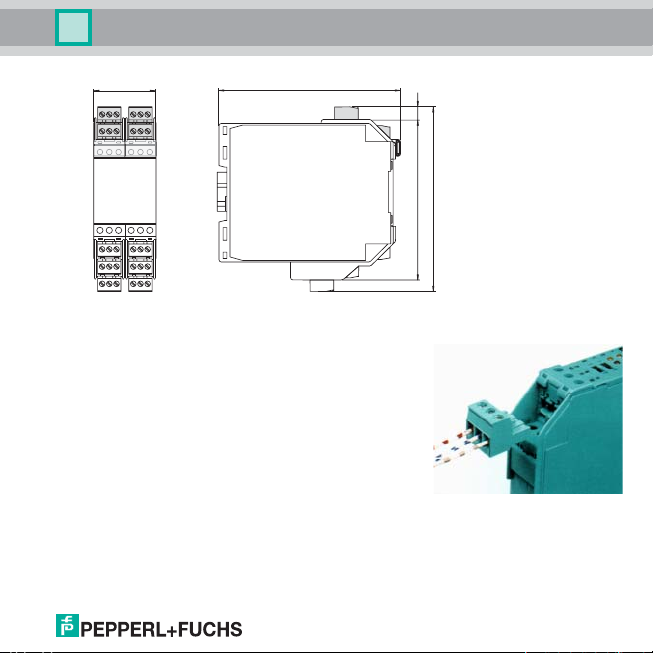
5.2 Connection
The detachable terminals of the KF-ser ies considerably simplify
the connection and the switch cabinet assembly. They make it
possible to replace devices quickly and without error if a
customer service becomes necessary.
Terminals are equipped with screws, are self-opening, have a
large connection area for a wire cross-section up to 2.5 mm²
and coded plugs, making it impossible to mix them up.
Date of issue 11/30/07 805639
Dimensions of the
KFD2-HLC-(Ex)1.D(.**) in mm
11940105 7
7
Page 10
HART Loop Converter KFD2-HLC-(Ex)1.D(.**)
2
2
I
Installation and connection
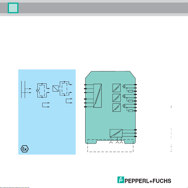
5.2.1 Connection input (field circuit)
The intrinsically safe field circuit is connected to the blue terminals 1 to 6 on the KFD2-HLC-Ex1.D(.**).
This may be conducted using DIN EN 60079-14-compliant leads into the hazardous area.
You can connect the following three operating modes:
1. any separately powered HART loop with a transmitter or positioner in a parallel circuit (as with
HART handheld terminals, terminals 2 and 3)
2. an active HART-compatible mA source, e. g. a separately powered HART transmitter (terminals 2
and 3, bridge between terminals 5 and 6)
3. a 2-wire HART transmitter (HART transmitter with analogue 4 mA ... 20 mA output signal) powered
by the HLC (terminals 1 and 3, bridge between terminals 4 and 5)
12 3
HART
Zone 0, 1, 2
Div. 1, 2
+
-
HART
HART
+
1+
2+
3-
4
5
6
KFD2-HLC-Ex1.D
Power Rail
7-
8+
9-
13+
14-
15+
19
20
21
22
23+
24-
24 V DCERR
8
+--
+--
+--
24 V DC
+
+
+
Zone
Div.
I
II
II
HART
Date of issue 11/30/07 805639
Page 11
HART Loop Converter KFD2-HLC-(Ex)1.D(.**)
Installation and connection
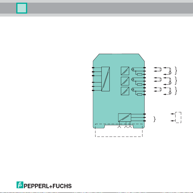
5.2.2 Connection output
The non-intrinsically safe field circuit is connected to the green terminals 1 to 6 on the KFD2-HLC-
1.D(.**).
The remaining green terminals have the following functions:
KFD2-HLC-Ex1.D
• Terminals 7 ... 9: output I, current
output as source (7/8) or sink (7/9)
• Terminals 13 ... 15: output II,
current output as source (13/14) or
sink (13/15)
• Terminals 19 ... 21: output III,
current output as source (19/20) or
sink (19/21)
• Terminals 22/24: HART handheld
terminal connection
• Terminals 23/24: power supply
24 V DC
Date of issue 11/30/07 805639
KFD2-HLC-Ex1.D
Power Rail
13+
1415+
19
20
21
22
23+
24-
24 V DCERR
78+
9-
+--
+--
+--
24 V DC
+
+
+
Zone 2
Div. 2
I
II
III
HART
9
Page 12

HART Loop Converter KFD2-HLC-(Ex)1.D(.**)
Installation and connection
KFD2-HLC-Ex1.D.2W
• Terminals 10 ... 12: output I
(relay 1 (change-over contact))
• Terminals 16 ... 18: output II
(relay 2 (change-over contact))
• Terminals 7 ... 9: output III, current
output as source (7/8) or sink (7/9)
• Terminals 13 ... 15: output IV,
current output as source (13/14) or
sink (13/15)
• Terminals 19 ... 21: output V,
current output as source (19/20) or
sink (19/21)
• Terminals 22/24: HART handheld
terminal connection
• Terminals 23/24: power supply
24 V DC
KFD2-HLC-Ex1.D.2W
Power Rail
10
I
11
12
16
17
II
18
7-
+
+
+
Zone 2
Div. 2
III
IV
V
HART
Date of issue 11/30/07 805639
8+
+--
913+
14-
+--
15+
19
20
+--
21
22
23+
24 V DC
24-
24 V DCERR
10
Page 13
HART Loop Converter KFD2-HLC-(Ex)1.D(.**)
Installation and connection
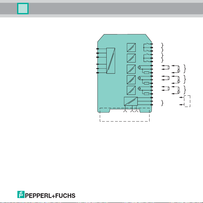
KFD2-HLC-Ex1.D.4S
• Terminals 10/11: output I
(relay 1 (change-over contact))
• Terminals 10/12: output II
(relay 2 (change-over contact))
• Terminals 16/17: output III
(relay 3 (change-over contact))
• Terminals 16/18: output IV
(relay 4 (change-over contact))
• Terminals 7 ... 9: output V, current
output as source (7/8) or sink (7/9)
• Terminals 13 ... 15: output VI,
current output as source (13/14) or
sink (13/15)
• Terminals 19 ... 21: output VII,
current output as source (19/20) or
sink (19/21)
• Terminals 22/24: HART handheld
terminal connection
• Terminals 23/24: power supply
24 V DC
More information on connecting the HLC (e. g. using the power rail with collective error message) can
be found in the data sheets and the K-System operating manual on our webpage www.pepperlfuchs.com (enter
Date of issue 11/30/07 805639
*HLC* in the product search).
KFD2-HLC-Ex1.D.4S
Power Rail
10
11
12
16
17
18
78+
913+
1415+
19
20
21
22
23+
24-
24 V DCERR
I
II
III
IV
+--
+--
+--
24 V DC
+
+
+
VII
Zone 2
Div. 2
V
VI
HART
11
Page 14
HART Loop Converter KFD2-HLC-(Ex)1.D(.**)
Installation and connection
5.3 Setting parameters of HART field device
In order to set the parameters of the connected HART field device, you will require a HART handheld
terminal which you can connect to terminals 22/24 or the field cables. Transmitting the HART signal
via the current outputs of the HLC is not possible.
When connecting the field cables, use an old handheld terminal if the field cables lead
through a hazardous area.
Warning
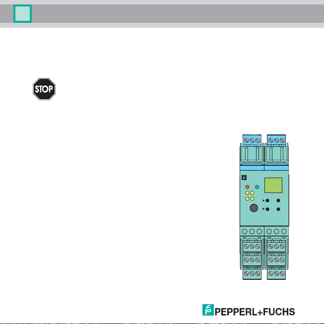
5.4 Front
The following are located on the front of the HLC:
• a display for showing the measured values, the current output values
and fault messages and for displaying in parameterization mode
• four keys for selecting the displayed values/current output value and for
setting the parameters of the HLC:
S (Up) T (Down) ESC (Escape) OK
• RS 232 serial interface for a connection to a PC for setting parameters
and diagnosis of the HLC using PACT ware
TM
(available from 2009)
• LED ERR (red) to indicate a fault
• LED PWR (green) to indicate the presence of the supply voltage
also for KFD2-HLC-(Ex)1.D.2W and KFD2-HLC-(Ex)1.D.4S:
• LED OUT 1 (yellow) to indicate that relay 1 is active
123
KFD2-HLCEx1.D.4S
1
IN /
CH
K
21
OUT
43
RS232
789
13 14 15
19 20 21
• LED OUT 2 (yellow) to indicate that relay 2 is active
also for KFD2-HLC-(Ex)1.D.4S:
• LED OUT 3 (yellow) to indicate that relay 3 is active
• LED OUT 4 (yellow) to indicate that relay 4 is active
PWR
456
ESC
OK
10 11 12
16 17 18
22 23 24
Date of issue 11/30/07 805639
12
Page 15
HART Loop Converter KFD2-HLC-(Ex)1.D(.**)
Installation and connection
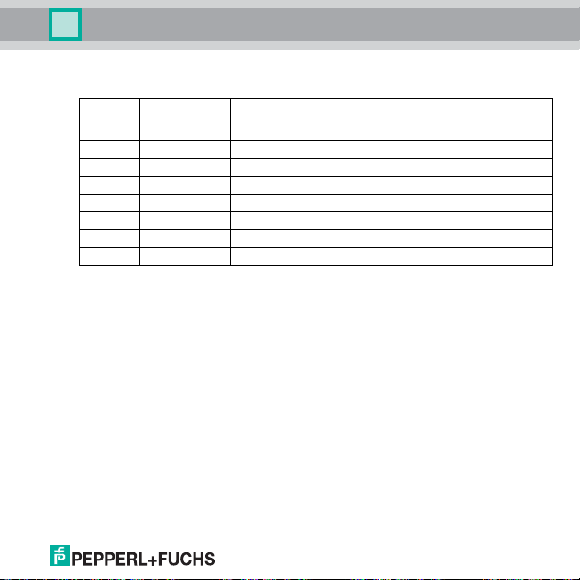
5.5 Meaning of LED indication
LED Indication Meaning
green off missing power
green regularly flashing power-up self-test phase (unit not yet working)
green on normal operating mode
yellow on Out 1 ... 4, output relay energised
red flashes briefly single HART error message received from the field device
red regularly flashing HART data invalid (communication loss or field device fault)
red on HLC self-test error detected (faulty unit, possible loss of functions)
red on HLC is in reset condition, all other LEDs are off
Date of issue 11/30/07 805639
13
Page 16

HART Loop Converter KFD2-HLC-(Ex)1.D(.**)
Display modes and error messages
6 Display modes and error messages
The following appear on the display in normal mode:
• the current values for HART variables PV, SV, TV, QV in the selected unit and
• the actual current output values Ch1, Ch2, Ch3 in mA.
• Please use the S and T keys to select the displayed measured value
or current output value.
• To select the units for the measured values see section 8.2.
• The display is updated every time the HLC receives a HART command 3 message from the field
device.
• Current output values are displayed as a four-digit number. The decimal point is set to give the best
possible resolution.
• The floating decimal values for the HART variables are displayed as follows:
− if possible as a four-digit number with decimal point and without an exponent (negative values
have three digits because of minus sign)
− a number may be rounded up (0.3456 appears as 0.346)
− if this display is not possible, the mantissa and exponent are displayed alternately.
If the restart inhibit (see section 8.5.5 and 8.5.7) is triggered but the device continues operating
normally, a corresponding message appears in the second line of the display.
If a fault occurs, one of the following messages is displayed until the fault is rectified:
• Err device fault (red LED lights up)
• Err communication error (red LED flashes)
• Err sensor fault (red LED flashes)
If switching the HLC on/off and checking the cables does not rectify the fault, please contact
Pepperl+Fuchs or the field device manufacturer.
The relays power down when a fault occurs.
For information on the behaviour of the current output in the event of a fault, see section 8.4.4.
Date of issue 11/30/07 805639
14
Page 17

HART Loop Converter KFD2-HLC-(Ex)1.D(.**)
Description of HART operations:
7 Description of HART operations
Dynamic variable acquisition
HART command 3 is always used to obtain the applicable dynamic variables, either directly or by
activating it in the Burst Mode.
Burst Mode operation
The HART Burst Mode is the HLC preferred one because it ensures a faster operation. The HLC will
therefore always try to set the connected device in the Burst Mode. The Burst Mode activation
command will be sent to the field device in the following situations:
• after an HLC unit power-up (or after an internally generated reset)
• after a field device power-up
• when the communication with the field device is recovered after a time-out.
"Command and answer" operation
If the field device doesn't support the Burst Mode, the HLC will use the normal "command and answer"
mode.
Burst mode recovery procedure
If the HLC stop receiving the burst frames, the following recovery procedure will be applied:
• The HLC immediately goes into the "command and answer" mode.
• The HLC then check if another HART master is sending messages on the loop; if another master
is found, the HLC will not try to re-enable the Burst Mode.
• If no other HART master is found the HLC will keep trying to re-enable the Burst Mode.
• As soon as any Burst frame is again received, the HLC immediately return to the Burst Mode.
This procedure makes possible for another HART master to temporary disable the Burst Mode, as
could be required for servicing reasons.
"Communication-loss" time-out
If the time-out is exceeded at missing communication, then all outputs switch in a defined safe state.
The time-out can be set.
Date of issue 11/30/07 805639
15
Page 18
HART Loop Converter KFD2-HLC-(Ex)1.D(.**)
Editing device data: Parameterization mode
8 Editing device data
A change in device data will change the operation of the device!
Before entering new data into the device, you should ascertain that no danger to the
installation will result.
Warning
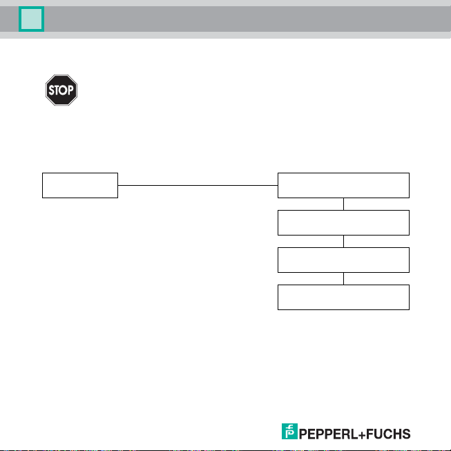
8.1 Parameterization mode
8.1.1 Invocation
Display mode
You can return to display mode from any point in the menu in parameterization mode by pressing the
ESC key (possibly multiple times). If you do not press any key for 10 minutes in parameterization
mode, the device automatically switches back into display mode.
OK + ESC (simultaneously for 1 sec) →
← ESC
Main menu parameterization mode
Unit (8.2)
HARTcom (8.3)
Output (8.4 and 8.5)
Service (8.6)
Date of issue 11/30/07 805639
16
Page 19

HART Loop Converter KFD2-HLC-(Ex)1.D(.**)
Editing device data: Parameterization mode
8.1.2 Password
You can protect the parameter s ettings from unauthorized changes using a passwor d (see section 8.6,
inactive when HLC delivered).
If password protection is active, the various settings in parameterization mode can be viewed without
entering the password, but not changed.
The password cannot be changed and is 1234.
The password is entered as follows:
• On the first attempt to make a change, the device immediately prompts for a password.
• The first digit of the password flashes.
• Now enter each number of the password by pressing the S and T keys (numbers 0 to 9) and press
OK to confirm each individual number. The next digit of the password then flashes.
• You can abort password entry at any time by pressing ESC.
• If you enter the last digit and press OK to confirm but the password is incorrect, the last digit of the
password continues to flash. You can either enter the last digit again or press ESC to cancel the
entry and make another attempt from the beginning.
• If you enter the last digit, press OK to confirm and the password is correct, the parameter change
is accepted.
The password must be entered for each transition from display mode to parameterization mode, once
each time.
Date of issue 11/30/07 805639
17
Page 20

HART Loop Converter KFD2-HLC-(Ex)1.D(.**)
Editing device data: Parameterization mode
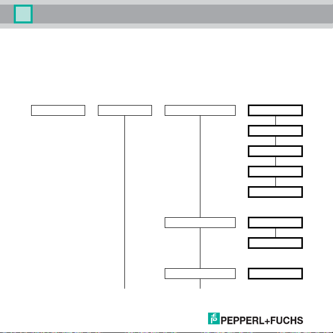
8.1.3 Navigation method
The following diagram illustrates the navigation method in parameterization mode using the S, T, OK
and ESC keys:
Iout1
OK →
← ESC
← ESC ← ESC
← ESC
← ESC
← ESC
Assignment
TS
Characteristic
TS
Start value
TS
End value
TS
Error current
OK →
4 - 20 NE43
Date of issue 11/30/07 805639
18
Page 21

HART Loop Converter KFD2-HLC-(Ex)1.D(.**)
Editing device data: Parameterization mode
8.1.4 Lowest menu level: select values, enter normal numbers
On the lowest level of the menu, you can either select one of several possible values, or enter a
number for the individual parameters.
Proceed as follows (for floating decimal number, see section 8.1.5):
Lowest menu level
Para meter
When entering normal numeric values, please note:
• If you press the S or T keys, the value changes step by step.
• If you hold the S or T keys, the value "rolls" to higher or lower values.
8.1.5 Lowest menu level: enter floating decimal numbers
Enter floating decimal numbers as follows:
• positive numbers with four-digit mantissa, decimal point in or after the mantissa, exponent in three
stages from E-33 and E00 to E33
• negative numbers with minus sign, three-digit mantissa, decimal point in or after the mantissa,
exponent in three stages from E-33 and E00 to E33
Date of issue 11/30/07 805639
OK →
← ESC
← ESC
← ESC
Current value, flashing
S, T: ↓
New value, flashing,
not saved
OK ↓
New value, not flashing,
saved
19
Page 22

HART Loop Converter KFD2-HLC-(Ex)1.D(.**)
Editing device data: Parameterization mode
The following table provides an overview:
Positive number Entry Negative number Entry
43 210 000 43.21 E06 - 3 210 000 -3.21 E06
4 321 000 4321 E03 - 321 000 -321 E03
432 100 432.1 E03 - 32 100 -32.1 E03
43 210 43.21 E03 - 3 210 -3.21 E03
4 321 4321 E00 - 321 -321 E00
432.1 432 .1 E00 - 32.1 -32.1 E00
43.21 43.21 E00 - 3.21 -3.21 E00
1.234 1.234 E00
0.123 4 123.4 E-03 - 0.123 -123 E-03
0.012 34 12.34 E-03 - 0.012 3 -12.3 E-03
0.001 234 1.234 E-03 - 0.001 23 -1.23 E-03
0.000 123 4 123.4 E-06 - 0.000 123 -123 E-06
Floating decimal numbers contain six elements, which you must enter individually: four digits for the
mantissa or three digits with minus sign for the mantissa, position of the decimal point in or after the
mantissa, exponent. Make entries as follows:
• When accessing the lowest menu level, the total current value of the floating decimal number
(mantissa and exponent) flashes first of all. Press OK again. The first digit of the mantissa (or the
minus sign) flashes.
• Now enter each number of the mantissa individually by pressing the S and T keys: numbers 0 to
9, minus sign in the first position below 0 (press the T key). Press OK to confirm each entry. The
next digit of the mantissa then flashes.
• When you enter the last digit of the mantissa, the digit after the decimal point flashes. Determine
the required position of the decimal point by pressing the S and T keys and press OK to confirm.
The exponent appears and begins to flash.
• Now enter the exponent value by pressing the S and T keys (values from E-33 and E00 to E33 in
three steps) and press OK to confirm.
Date of issue 11/30/07 805639
20
Page 23

HART Loop Converter KFD2-HLC-(Ex)1.D(.**)
Editing device data: Unit
8.2 Unit
The following illustration shows the unit menu. Items from the lowest menu level are outlined in bold.
Unit —— PV —— Type —— auto
Custom tag —— (see below)
SV —— same as PV
TV —— same as PV
QV —— same as PV
• If you select auto, the unit transferred by the HART field device for the relevant variable (PV, SV,
TV, QV) appears on the HLC display.
• If you select custom, the Custom Tag appears on the HLC display as the unit for the relevant
variable (PV, SV, TV, QV).
• The selected unit is also used for all corresponding settings in parameterization mode.
Enter the Custom Tag as follows:
• Initial display: ↵ (or previous Custom Tag with as first character and ↵ )
• Select one of the eight positions in front of ↵ for the by pressing the T or S keys.
• Select OK. The flashes.
• Select a character by pressing the S or T keys. Select OK.
• Repeat the position and character selection process until the character string is complete.
Date of issue 11/30/07 805639
custom
21
Page 24

HART Loop Converter KFD2-HLC-(Ex)1.D(.**)
Editing device data: HARTcom
• Leave empty spaces if necessary.
• Select the position ↵ and then press OK. The character string is saved.
• Or press ESC to exit Custom Tag entry mode without accepting the changes.
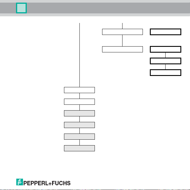
8.3 HARTcom
The following illustration sh ows the HART communication menu. Items from the lowes t menu level are
outlined in bold.
HARTcom —— Mode (8.3.1) —— secondary
primary
TimeOut (8.3.2) —— 5 s ...60 s
ShortAddress (8.3.3) —— 0 ... 15
LocateMethod (8.3.3) —— fixed
search
Rebuild (8.3.4) —— On Rebuild
OFF Rebuild
Date of issue 11/30/07 805639
22
Page 25

HART Loop Converter KFD2-HLC-(Ex)1.D(.**)
Editing device data: HARTcom
If available, the HLC activates Burst Mode for the HART field device to achieve maximum
communication speed. The HLC uses the universal HART command 3 to retrieve variables (PV, SV,
TV, QV, if available).
8.3.1 Mode
Depending on the setting, the HLC operates as a primary or secondary HART master device according
to HART standards and is fully compatible with each HART handheld terminal and any other HART
master devices.
8.3.2 TimeOut
If the HLC does not receive a valid HART message after the preset time, the fault indication
Communication fault is issued. Time-out range is 5 s to 60 s in increments of 5 seconds.
8.3.3 ShortAddress and LocateMethod
More than one HART field device may be present in a HART loop, as specified in the HART standards.
However, the HLC can only communicate with one HART field device at a time. This field device is
identified during the localization phase.
• If you select LocateMethod fixed, the HLC communicates with the field device that was assigned a
short address under ShortAddress.
• If you select LocateMethod, the HLC runs a search for the shortest address – beginning with the
address assigned under ShortAddress – and then communicates with this device. The device
address is saved to accelerate the next start-up process under ShortAddress.
8.3.4 Rebuild
If the connection to the HART field device is lost, you can use Rebuild to run through the localization
phase without having to switch the HLC off and on again.
Pressing the OK key when On Rebuild is flashing prompts the HLC to start searching for connected
HART devices (see section 8.3.3) in the same way as during start-up.
Date of issue 11/30/07 805639
23
Page 26
HART Loop Converter KFD2-HLC-(Ex)1.D(.**)
Editing device data: Current outputs
8.4 Current outputs
The following illustrations show the current output menus. Items from the lowest menu level are
outlined in bold.
Pressing the OK key in the Iout1, Iout2 and Iout3 menu items gives you access to a menu for entering
separate parameters for the selected current output. The three menus are identical and are therefore
described only once. For the relay outputs on the KFD2-HLC-(Ex)1.D.2W or KFD2-HLC-(Ex)1.D.4S,
see section 8.5.
Output —— Iout1 —— Assignment8.4.1) —— disabled
Characteristic (8.4.2) —— 4 - 20 unlimited
4 - 20 NE43
Start value —— (8.4.3)
Continued on next page
PV
SV
TV
QV
Date of issue 11/30/07 805639
24
Page 27
Date of issue 11/30/07 805639
HART Loop Converter KFD2-HLC-(Ex)1.D(.**)
Editing device data: Current outputs
End value —— (8.4.3)
Error current (8.4.4) —— down
Iout2
Iout3
Rel1
Rel2
Rel3
Rel4
up
hold
25
Page 28

HART Loop Converter KFD2-HLC-(Ex)1.D(.**)
Editing device data: Current outputs
8.4.1 Assignment
The values of the HART variable selected here (PV, SV, TV, QV) are displayed at the current output
(see section 8.4.2). The number of available variables depends on the HART field device.
If disabled is selected, the downscale error current is issued constantly at the current output (0 mA or
2 mA depending on the characteristic, see section 8.4.4).
8.4.2 Characteristic
The Start value and End value parameters (see section 8.4.3) allow you to define a value range for
the assigned HART variable, which is used as a measurement range in the application. This
measurements range is represented at the output signal in linear form (start value to 4 mA, end value
to 20 mA, proportional intermediate values).
• In the characteristic 4 - 20 unlimited, you can evaluate measurement range shortfalls up to 0 mA
and excess measurement ranges up to approx. 23 mA.
• In the characteristic 4 - 20 NE43, you can evaluate measurement range shortf alls up to 3.8 mA and
excess measurement ranges up to 20.5 mA.
• Measurement ranges that exceed the specified linear range cannot be evaluated. If the range is
exceeded, the minimum and maximum stated values are issued continually.
Example of an illustration of a measurement range on the output signal
Characteristic 4 - 20 NE43, start value 2 bar, end value 10 bar
mA
20.5
20.0
4.0
3.8
0
21010.251.9
bar
Date of issue 11/30/07 805639
26
Page 29
HART Loop Converter KFD2-HLC-(Ex)1.D(.**)
Editing device data: Relay
8.4.3 Start value and end value
Please remember the following when entering the Start value and End value:
• Both values must be entered as floating decimal numbers in the unit selected under Unit (see
section 8.1.4 and 8.2).
• The start value must be 1 % smaller than the end value. This is checked by the device and a start
value bigger than the end value will not be accepted. In this case the end value must be entered
prior the start value.
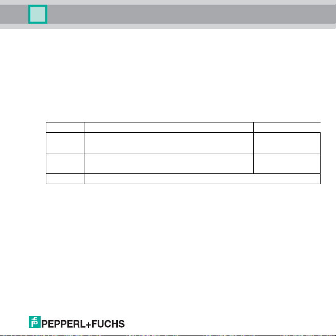
8.4.4 Error current
The following table shows what the current output issues for each characteristic after a fault.
Setting 4 mA ... 20 mA unlimited 4 mA ... 20 mA NE43
down
up
hold Last value measured before the fault
(does not differ from the shortfall of the start value)
(does not differ from the exceeded end value)
0 mA
approx. 23 mA
8.5 Relay
The following illustrations show menus for the relay outputs on the KFD2-HLC-(Ex)1.D.2W or KFD2HLC-(Ex)1.D.4S. For the current outputs, see section 8.4.
Pressing the OK key in the Rel1 and Rel2 menu items on the KFD2-HLC-(Ex)1.D.2W or Rel1 to Rel4
menu items on the KFD2-HLC-(Ex)1.D.4S gives you access to a menu for entering separate
parameters for the selected relay. The two or four menus are identical and are therefore described
only once.
On indicates that the function of a relay (Trip value or Fault indication) is enabled. If you want to enable
a different function, first call it up with the S and T keys. Then press the OK key twice. After the first
OK, you can cancel with ESC.
Date of issue 11/30/07 805639
2.0 mA
21.5 mA
27
Page 30

HART Loop Converter KFD2-HLC-(Ex)1.D(.**)
Editing device data: Relay
Output —— Iout1
Iout2
Iout3
Rel1 —— Trip value (8.5.1)
Fault indication (8.5.7)
Rel2
Rel3
Rel4
8.5.1 Trip value
The following illustrations show the menu levels that follow the Trip value menu item (see section 8.5).
Items from the lowest menu level are outlined in bold.
If the Trip value function is enabled (On), press the OK key in the Trip value menu item to access the
Assignment menu item. If you enable the Trip value function again (see section 8.5), pressing the OK
key a second time gives direct access to the Assignment menu item.
Date of issue 11/30/07 805639
28
Page 31

Date of issue 11/30/07 805639
HART Loop Converter KFD2-HLC-(Ex)1.D(.**)
Editing device data: Relay
Trip value (on) —— Assignment8.5.2) —— disabled
PV
SV
TV
QV
Min/Max (8.5.3) —— Min
Max
Trip point —— (8.5.4)
Hysteresis —— (8.5.4)
Continued on next page
29
Page 32

HART Loop Converter KFD2-HLC-(Ex)1.D(.**)
Editing device data: Relay
Switching mode (8.5.3) —— Passive
Active
Restart inhibit (8.5.5) —— On
OFF
Response delay (8.5.6) —— 0 s ... 250 s
8.5.2 Assignment
The values of the HART variables selected here (PV, SV, TV, QV) are monitored via the relay output
(see section 8.5.3). The number of available variables depends on the HART field device. If disabled
is selected, the relay remains without power permanently.
8.5.3 Switching characteristics
The Max or Min switching direction and the Active or Passive switching mode can be preset (see
section 8.5.1).
Application areas:
• Switching direction Max, switching mode Active: Alarm after trip overrange, e. g. horn on
• Switching direction Max, switching mode Passive: Shutdown after trip overrange, e. g. pump,
heating, ... off, if the Min/Max operation hysteresis is large (pump, heating, ... on/off)
• Switching direction Min, switching mode Active: Alarm after trip underrange, e. g. horn on
• Switching direction Min, switching mode Passive: Shutdown after trip underrange, e. g. pump,
heating, ... off, if the Min/Max operation hysteresis is large (pump, heating, ... on/off)
Date of issue 11/30/07 805639
30
Page 33

HART Loop Converter KFD2-HLC-(Ex)1.D(.**)
Editing device data: Relay
The following illustration shows the exact switching characteristics of the HLC:
8.5.4 Trip point and hysteresis
Please remember the following when entering values for Trip point and Hysteresis:
• Both values must be entered as floating decimal numbers in the unit selected under Unit (see
• The selected hysteresis must be > 1 % of the trip point to prevent the relay from vibrating.
Date of issue 11/30/07 805639
Measured value
Max. trip point
Max. - hysteresis
Min. + hysteresis
Min. trip point
Switching direction Max, switching mode Active:
energized
de-energized
Switching direction Max, switching mode Passive:
energized
de-energized
Switching direction Min, switching mode Active:
energized
de-energized
Switching direction Min, switching mode Passive:
energized
de-energized
section 8.1.4 and 8.2).
Time
31
Page 34

HART Loop Converter KFD2-HLC-(Ex)1.D(.**)
Editing device data: Relay
8.5.5 Restart inhibit
With the restart inhibit, you prevent momentary trip violations from going unnoticed by
operating personnel.
If Restart inhibit on is selected, after the relay switches, the new status remains active until the ESC
key is pressed or the device is restarted. This will rese t the relay unless the trip violation is still pending.
8.5.6 Response delay
Setting a response delay > 0 seconds prevents momentary trip violations from triggering an alarm.
• The relay only switches when the trip value exceeds or falls below the trip point for a period longer
than the delay time without interruptions.
• The relay only switches back when the trip value exceeds or falls below the trip point/hysteresis for
a period longer than the delay time without interruptions.
• Momentary excesses/shortfalls have no effect.
The following illustration shows the switching characteristics, in this example, switching dire ction Max,
switching mode Active.
Measured value
Max. trip point
Max. - hysteresis
Switching direction Max, switching mode Active, with delay
energized
de-energized
Delay
Delay
Time
Date of issue 11/30/07 805639
32
Page 35

HART Loop Converter KFD2-HLC-(Ex)1.D(.**)
Editing device data: Relay
8.5.7 Fault indication
The following illustration shows the menu levels that follow the Fault indication menu item (see
section 8.5). Items from the lowest menu level are outlined in bold.
If the fault indication function is enabled (On), press the OK key in the Fault indication menu item to
access the Restart inhibit menu item. If you enable the Fault indication function again (see
section 8.5), pressing the OK key a second time gives direct access to the Restart inhibit menu item.
Fault indication (on) —— Restart inhibit —— On
Off
A relay with the fault indication function is energized during normal operation. The relay is deenergized if the device detects a fault (see section 6).
With the restart inhibit, you prevent momentary fault indications from going unnoticed by operating
personnel.
If Restart inhibit on is selected, after the relay switches, the new status remains active until the ESC
key is pressed or the device is restarted. This will reset the relay unless the fault indication is still
pending.
Date of issue 11/30/07 805639
33
Page 36

HART Loop Converter KFD2-HLC-(Ex)1.D(.**)
Editing device data: Service
8.6 Service
The following illustration shows the service parameter menus. Items from the lowest menu level are
outlined in bold.
Service —— Language —— ENG (English)
DE (German)
Password (8.1.3) —— On password
OFF password
Reset (see below) —— On reset
OFF reset
Reset: Pressing the OK key when On Reset is flashing resets all settings on the HLC to default (see
section 8.7). Any entries that you have made in parameterization mode are lost.
Date of issue 11/30/07 805639
34
Page 37

HART Loop Converter KFD2-HLC-(Ex)1.D(.**)
Editing device data: Default settings
8.7 Default settings
Rel1 and Rel2 are available with the KFD2-HLC-(Ex)1.D.2W and KFD2-HLC-(Ex)1.D.4S, Rel3 and
Rel4 are available with the KFD2-HLC-(Ex)1.D.4S.
Menu Parameter Default setting Separate value
Unit PV → type auto
HARTcom Mode primary
Output Iout1 Assignment disabled
Output Iout2 Assignment disabled
Output Iout3 Assignment disabled
Date of issue 11/30/07 805639
SV → type auto
TV → type auto
QV → type auto
TimeOut 10 sec
ShortAddress 0
LocateMethod search
Characteristic 4 - 20 NE43
Start value 0.000
End value 100.0
Error current down
Characteristic 4 - 20 NE43
Start value 0.000
End value 100.0
Error current down
Characteristic 4 - 20 NE43
Start value 0.000
End value 100.0
35
Page 38

HART Loop Converter KFD2-HLC-(Ex)1.D(.**)
Editing device data: Default settings
Menu Parameter Default setting Separate value
Error current down
Output Rel1 Trip value On (= selected)
Output Rel2 Trip value On (= selected)
Output Rel3 Trip value On (= selected)
Assignment disabled
Min/Max (= switching direction) Min
Trip point 80.00
Hysteresis 10.00
Switching mode passive
Restart inhibit OFF restart inhibit
Response delay 0 sec
Fault indication not selected
Assignment disabled
Min/Max (= switching direction) Min
Trip point 80.00
Hysteresis 10.00
Switching mode passive
Restart inhibit OFF restart inhibit
Response delay 0 sec
Fault indication not selected
Assignment disabled
Min/Max (= switching direction) Min
Trip point 80.00
Hysteresis 10.00
Switching mode passive
Date of issue 11/30/07 805639
36
Page 39
HART Loop Converter KFD2-HLC-(Ex)1.D(.**)
Editing device data: Default settings
Menu Parameter Default setting Separate value
Restart inhibit OFF restart inhibit
Response delay 0 sec
Fault indication not selected
Output Rel4 Trip value On (= selected)
Assignment disabled
Min/Max (= switching direction) Min
Trip point 80.00
Hysteresis 10.00
Switching mode passive
Restart inhibit OFF restart inhibit
Response delay 0 sec
Fault indication not selected
Service Language ENG
Password OFF PASS
Date of issue 11/30/07 805639
37
Page 40

HART Loop Converter KFD2-HLC-(Ex)1.D(.**)
Notes
Date of issue 11/30/07 805639
38
Page 41

Date of issue 11/30/07 805639
HART Loop Converter KFD2-HLC-(Ex)1.D(.**)
Notes
39
Page 42

HART Loop Converter KFD2-HLC-(Ex)1.D(.**)
Notes
Date of issue 11/30/07 805639
40
Page 43

With regard to the supply of products, the current iss ue of the following document is applicable:
The general terms of delivery for products a nd services of the electrical industry, as publi shed
by the central association of the "Elektrotechni k und Elektroindustrie (ZVEI) e.V.",
including the supplementary clause "Extende d reservation of title".
Page 44

PROCESS AUTOMATION –
PROTECTING YOUR PROCESS
Worldwide Headquarters
Pepperl+Fuchs GmbH
68307 Mannheim · Germany
Tel. +49 621 776-0
E-mail: info@de.pepperl-fuchs.com
USA Headquarters
Pepperl+Fuchs Inc.
Twinsburg, Ohio 44087 · USA
Tel. +1 330 4253555
E-mail: sales@us.pepperl-fuchs.com
Asia Pacific Headquarters
Pepperl+Fuchs Pte Ltd.
Company Registration No. 199003130E
Singapore 139942
Tel. +65 67799091
E-mail: sales@sg.pepperl-fuchs.com
www.pepperl-fuchs.com
Subject to modifications
Copyright PEPPERL+FUCHS • Printed in Germany
DOCT-1377A 805639
11/2007
 Loading...