

Page 1
2
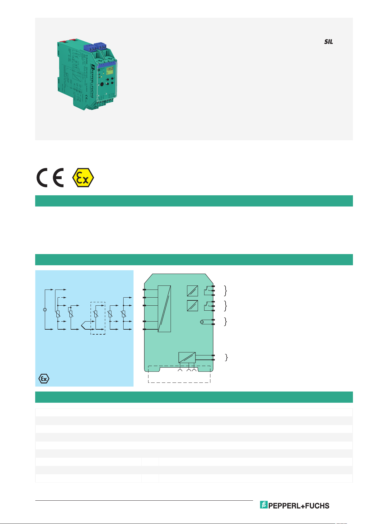
Function
Zone 2Zone 0, 1, 2
KFD2-GUT-Ex1.D
16
17
18
10
11
12
I
II
78+
III
4
3
6
2
1
T T
+
-
V
mA
+
-
T
24 V DC
23+
24-
Power Rail
24 V DCERR
K-CJC-**
Germany: +49 621 776 2222Pepperl+Fuchs Group
Refer to "General Notes Relating to Pepperl+Fuchs Product Information".
USA: +1 330 486 0002 Singapore: +65 6779 9091
www.pepperl-fuchs.com pa-info@us.pepperl-fuchs.com pa-info@sg.pepperl-fuchs.com
pa-info@de.pepperl-fuchs.com
Temperature Converter with Trip Values
KFD2-GUT-Ex1.D
1-channel isolated barrier
<
24 V DC supply (Power Rail)
<
Thermocouple, RTD, potentiometer or voltage input
<
Redundant TC input
<
Current output 0/4 mA ... 20 mA
<
2 relay contact outputs
<
Configurable by PACTware or keypad
<
Line fault (LFD) and sensor burnout detection
<
Up to SIL 2 acc. to IEC 61508/IEC 61511
<
This isolated barrier is used for intrinsic safety applications.
The device converts the signal of a resistance thermometer, thermocouple, potentiometer, or voltage source to a proportional output current. It
also provides a relay trip value.
The removable terminal block K-CJC-** is available as an accessory for internal cold junction compensation of thermocouples.
A fault is signalized by LEDs acc. to NAMUR NE44 and a separate collective error message output.
The device is easily configured by the use of the PACTware configuration software.
For additional information, refer to the manual and www.pepperl-fuchs.com.
Connection
Technical Data
General specifications
Signal type Analog input
Functional safety related parameters
Safety Integrity Level (SIL) SIL 2
Supply
Connection terminals 23+, 24- or power feed module/Power Rail
Rated voltage U
Rated current I
Power dissipation/power consumption ≤ 2 W / 2.2 W
Release date: 2020-09-23 Date of issue: 2020-09-23 Filename: 231225_eng.pdf
r
r
20 ... 30 V DC
approx. 100 mA
1
Page 2

Temperature Converter with Trip Values KFD2-GUT-Ex1.D
Germany: +49 621 776 2222Pepperl+Fuchs Group
Refer to "General Notes Relating to Pepperl+Fuchs Product Information".
USA: +1 330 486 0002 Singapore: +65 6779 9091
www.pepperl-fuchs.com pa-info@us.pepperl-fuchs.com pa-info@sg.pepperl-fuchs.com
pa-info@de.pepperl-fuchs.com
Technical Data
Interface
Programming interface programming socket
Input
Connection side field side
Connection terminals 1, 2, 3, 4, 6
RTD Pt100, Pt500, Pt1000, Ni100, Ni1000
Types of measuring 2-, 3-, 4-wire technology
Lead resistance max. 50 Ω
Measurement loop monitoring sensor breakage, sensor short-circuit
Thermocouples type B, E, J, K, L, N, R, S, T (IEC 584-1: 1995)
Cold junction compensation external and internal
Measurement loop monitoring sensor breakage
Potentiometer 0.8 ... 20 kΩ
Types of measuring 2-, 3-, 5-wire technology
Voltage 0 ... 10 V , 2 ... 10 V , 0 ... 1 V , -100 ... 100 mV
Input resistance ≥ 250 kΩ (0 ... 10 V)
Measuring current approx. 400 µA with resistance measuring sensor
Output
Connection side control side
Connection output I: terminals 10, 11, 12
Output I, II relay
Contact loading 250 V AC / 2 A / cos φ ≥ 0.7 ; 40 DC / 2 A
Mechanical life 5 x 10⁷ switching cycles
Energized/De-energized delay approx. 20 ms / approx. 20 ms
Output III Analog current output
Current range 0 ... 20 mA or 4 ... 20 mA
Open loop voltage max. 24 V DC
Load max. 650 Ω
Fault signal downscale I ≤ 3.6 mA, upscale I ≥ 21 mA (acc. NAMUR NE43)
Collective error message Power Rail
Transfer characteristics
Deviation
Temperature effect Input: 0.005 %/K (50 ppm) of span ; current output: 0.005 %/K (50 ppm) of span
RTD max. 0.2 % of span
Thermocouples max. 10µV
Voltage 0.1 % of span
Potentiometer 0.1 % of span when < 5 kΩ
Current output max. 20 µA
Sampling rate approx. 700 ms
Galvanic isolation
Input/Other circuits reinforced insulation according to IEC/EN 61010-1, rated insulation voltage 300 V
Output I, II against eachother reinforced insulation according to IEC/EN 61010-1, rated insulation voltage 300 V
Output I, II/other circuits reinforced insulation according to IEC/EN 61010-1, rated insulation voltage 300 V
Output III/power supply and collective error reinforced insulation according to IEC/EN 61010-1, rated insulation voltage 300 V
Interface/power supply reinforced insulation according to IEC/EN 61010-1, rated insulation voltage 300 V
Indicators/settings
Display elements LEDs , display
Control elements Control panel
Configuration via operating buttons
Release date: 2020-09-23 Date of issue: 2020-09-23 Filename: 231225_eng.pdf
min. 1 MΩ (0 ... 1 V, -100 ... 100 mV)
output II: terminals 16, 17, 18
output III: terminals 8+, 7-
deviation of CJC: ±0.8 K
0.5 % of span when > 5 kΩ
via PACTware
eff
eff
eff
eff
eff
2
Page 3

Temperature Converter with Trip Values KFD2-GUT-Ex1.D
Germany: +49 621 776 2222Pepperl+Fuchs Group
Refer to "General Notes Relating to Pepperl+Fuchs Product Information".
USA: +1 330 486 0002 Singapore: +65 6779 9091
www.pepperl-fuchs.com pa-info@us.pepperl-fuchs.com pa-info@sg.pepperl-fuchs.com
pa-info@de.pepperl-fuchs.com
Technical Data
Labeling space for labeling at the front
Directive conformity
Electromagnetic compatibility
Directive 2014/30/EU EN 61326-1:2013 (industrial locations)
Low voltage
Directive 2014/35/EU EN 61010-1:2010
Conformity
Electromagnetic compatibility NE 21:2007
Degree of protection IEC 60529:2001
Ambient conditions
Ambient temperature -20 ... 60 °C (-4 ... 140 °F)
Mechanical specifications
Degree of protection IP20
Connection screw terminals
Mass 300 g
Dimensions 40 x 119 x 115 mm (1.6 x 4.7 x 4.5 inch) , housing type C3
Mounting on 35 mm DIN mounting rail acc. to EN 60715:2001
Data for application in connection with hazardous areas
EU-type examination certificate TÜV 03 ATEX 2140
Marking 1 II (1)G [Ex ia] IIC , 1 II (1)D [Ex iaD]
Input Ex ia IIC, Ex iaD
Supply
Maximum safe voltage U
Input terminals 2, 6 (for active equipment)
Voltage U
Current I
Power P
Voltage U
Current I
Power P
Inputs terminals 1, 2, 3, 4, 6 (for passive equipment)
Voltage U
Current I
Power P
o
o
o
Output
Contact loading 253 V AC/2 A/cos φ > 0.7; 40 V DC/2 A resistive load (TÜV 03 ATEX 2140)
40 V DC (Attention! The rated voltage can be lower.)
m
13.1 V
o
8 mA
o
67 mW
o
29 V
i
11 mA
i
200 mW
i
13.1 V
21 mA
67 mW
Analog output
Maximum safe voltage U
40 V (Attention! The rated voltage can be lower.)
m
Interface
Maximum safe voltage U
40 V (Attention! The rated voltage can be lower.) , RS 232
m
Certificate PF 08 CERT 1213 X
Marking 1 II 3G Ex nA nC IIC T4 Gc
Output I, II
Contact loading 50 V AC/2 A/cos φ > 0.7; 40 V DC/1 A resistive load
Galvanic isolation
Input/Other circuits safe electrical isolation acc. to IEC/EN 60079-11, voltage peak value 375 V
Directive conformity
Directive 2014/34/EU EN 60079-0:2012+A11:2013 , EN 60079-11:2012 , EN 60079-15:2010
International approvals
IECEx approval
IECEx certificate IECEx TUN 09.0019
IECEx marking [Ex ia Ga] IIC , [Ex ia Da] IIIC , [Ex ia Ma] I
Release date: 2020-09-23 Date of issue: 2020-09-23 Filename: 231225_eng.pdf
3
Page 4

ESC
OK
KFD2-GUTEx1.D
RS232
PWR
1 2
ERR
OUT
19 21
15
9
13
7
20
14
8
22 24
18
12
16
10
23
17
11
132 465
Front view
Removable terminals
green
Removable terminals
blue
Keypad
LC display
LED green:
Power supply
Programming jack
Place for labeling
LED red:
Fault signal
LED yellow:
Output II
LED yellow:
Output I
Temperature Converter with Trip Values KFD2-GUT-Ex1.D
Germany: +49 621 776 2222Pepperl+Fuchs Group
Refer to "General Notes Relating to Pepperl+Fuchs Product Information".
USA: +1 330 486 0002 Singapore: +65 6779 9091
www.pepperl-fuchs.com pa-info@us.pepperl-fuchs.com pa-info@sg.pepperl-fuchs.com
pa-info@de.pepperl-fuchs.com
Technical Data
General information
Supplementary information Observe the certificates, declarations of conformity, instruction manuals, and manuals
where applicable. For information see www.pepperl-fuchs.com.
Assembly
Accessories
DTM Interface
Technology
PACTware 5.X FDT Framework
K-ADP-USB
KFD2-EB2 Power Feed Module
UPR-03 Universal Power Rail with end caps and cover, 3 conductors, length: 2 m
UPR-03-M Universal Power Rail with end caps and cover, 3 conductors, length: 1,6 m
UPR-03-S Universal Power Rail with end caps and cover, 3 conductors, length: 0.8 m
K-DUCT-BU
K-DUCT-BU-UPR-03 Profile rail with UPR-03- * insert, 3 conductors, wiring comb field side blue
Release date: 2020-09-23 Date of issue: 2020-09-23 Filename: 231225_eng.pdf
4
Page 5

Temperature Converter with Trip Values KFD2-GUT-Ex1.D
Germany: +49 621 776 2222Pepperl+Fuchs Group
Refer to "General Notes Relating to Pepperl+Fuchs Product Information".
USA: +1 330 486 0002 Singapore: +65 6779 9091
www.pepperl-fuchs.com pa-info@us.pepperl-fuchs.com pa-info@sg.pepperl-fuchs.com
pa-info@de.pepperl-fuchs.com
Accessories
K-CJC-BU
Release date: 2020-09-23 Date of issue: 2020-09-23 Filename: 231225_eng.pdf
5
Page 6

Germany: +49 621 776 2222Pepperl+Fuchs Group
Refer to "General Notes Relating to Pepperl+Fuchs Product Information".
USA: +1 330 486 0002 Singapore: +65 6779 9091
www.pepperl-fuchs.com pa-info@us.pepperl-fuchs.com pa-info@sg.pepperl-fuchs.com
pa-info@de.pepperl-fuchs.com
Temperature Converter with Trip Values
2
1
6
+
+
-
-
K-CJC-**
A
B
KFD2-GUT-Ex1.D
Application
Redundant thermocouple
For higher availability it is possible to connect a second redundant thermocouple (B) of the same type to the temperature
converter. The cold junction temperature is taken from the connected terminal block.
If the deviation of the both thermocouples (A and B) exceed the selected tolerance, an error will occur. If a lead breakage of one
thermocouple (e. g. A) has been detected, an error message occurs and the value of the second thermocouple (B) will be taken
for futher calculation.
Release date: 2020-09-23 Date of issue: 2020-09-23 Filename: 231225_eng.pdf
6
 Loading...