

Page 1
ISO9001
MANUAL
PROCESS AUTOMATION
Temperature Trip
Amplifier
KFD2-GU-(Ex)1
Page 2

Temperature Trip Amplifier KFD2-GU-(Ex)1
With regard to the supply of products, the current issue of the following document is applicable:
The General Terms of Delivery for Products and Services of the Electrical Industry,
published by the Central Association of the Electrical Industry (Zentralverband Elektrotechnik
und Elektroindustrie (ZVEI) e.V.) in its most recent version as well as the supplementary clause:
"Expanded reservation of proprietorship"
Page 3

Temperature Trip Amplifier KFD2-GU-(Ex)1
Table of Contents
1 Symbols Used in this Document . . . . . . . . . . . . . . . . . . . . . . . . . . 2
2 Overview . . . . . . . . . . . . . . . . . . . . . . . . . . . . . . . . . . . . . . . . . . . . . . 2
2.1 Application. . . . . . . . . . . . . . . . . . . . . . . . . . . . . . . . . . . . . . . . . . . . . . . . . . . . . . 2
2.2 Versions . . . . . . . . . . . . . . . . . . . . . . . . . . . . . . . . . . . . . . . . . . . . . . . . . . . . . . . . 3
3 Safety Instructions. . . . . . . . . . . . . . . . . . . . . . . . . . . . . . . . . . . . . . 4
4 Explosion Protection . . . . . . . . . . . . . . . . . . . . . . . . . . . . . . . . . . . . 5
5 Mounting and Connection . . . . . . . . . . . . . . . . . . . . . . . . . . . . . . . 5
5.1 Mounting . . . . . . . . . . . . . . . . . . . . . . . . . . . . . . . . . . . . . . . . . . . . . . . . . . . . . . . 5
5.2 Connection. . . . . . . . . . . . . . . . . . . . . . . . . . . . . . . . . . . . . . . . . . . . . . . . . . . . . . 6
5.3 Operating and Indicating Elements . . . . . . . . . . . . . . . . . . . . . . . . . . . . . . . . 8
6 Device Configuration via Software . . . . . . . . . . . . . . . . . . . . . . . . 9
6.1 Connection Between Device and Computer . . . . . . . . . . . . . . . . . . . . . . . . . . 9
6.2 Communication Driver . . . . . . . . . . . . . . . . . . . . . . . . . . . . . . . . . . . . . . . . . . . 10
6.3 Monitor Functions . . . . . . . . . . . . . . . . . . . . . . . . . . . . . . . . . . . . . . . . . . . . . . 11
6.4 Simulation Function . . . . . . . . . . . . . . . . . . . . . . . . . . . . . . . . . . . . . . . . . . . . 12
6.5 Diagnosis . . . . . . . . . . . . . . . . . . . . . . . . . . . . . . . . . . . . . . . . . . . . . . . . . . . . . 13
284503 2015-09
7 Working with Device Data. . . . . . . . . . . . . . . . . . . . . . . . . . . . . . . 14
7.1 Menu Information and Description . . . . . . . . . . . . . . . . . . . . . . . . . . . . . . . . . 14
7.2 Menu Parameter Input . . . . . . . . . . . . . . . . . . . . . . . . . . . . . . . . . . . . . . . . . . 16
7.3 Menu Parameter Output . . . . . . . . . . . . . . . . . . . . . . . . . . . . . . . . . . . . . . . . . . 18
7.4 Switching Behaviour of the Relays. . . . . . . . . . . . . . . . . . . . . . . . . . . . . . . . . 19
1
Page 4
Temperature Trip Amplifier KFD2-GU-(Ex)1
Warning
Attention
Note
Symbols Used in this Document
1 Symbols Used in this Document
This symbol indicates a warning about a possible danger.
Failure to observe this warning may result in personal injury or death, or property
damage or destruction.
This symbol warns of a possible fault.
If the instruction given in this warning is not heeded, the device and any systems or
plants connected to it could develop a fault or even fail completely.
This symbol brings important information to your attention.
2Overview
2.1 Application
The devices of the K-System from Pepperl+Fuchs are used to transmit signals between field devices
and the process control system or control.
Devices with the "Ex" code in their type identifiers are suitable for connection to field devices in the
hazardous area. The field current circuits of these devices are intrinsically safe and are galvanically
isolated from the not intrinsically safe circuits. The devices thus represent an electrical isolation
between the hazardous area and the safe area within a system.
Devices without an "Ex" code can be used for signal transmission between field devices in the safe area
and the process control system or the control.
2
284503 2015-09
Page 5
Temperature Trip Amplifier KFD2-GU-(Ex)1
Overview
The temperature trip amplifier KFD2-GU-(Ex)1 of the
K-system are used for temperature measurement.
Further information (e. g. certificates, the data sheets
for the device and the manual for the K-system) can
be found on our Internet page www.pepperlfuchs.com/pa (under product search, enter *GU*).
• You can connect resistance temperature sensors or thermocouples to
the input of the device (types: B, E, J, K, L, N, R, S, T). The device can also process a unit current
signal or a unit voltage signal.
• Two different limit values of the input signal can be monitored with the aid of the two relay outputs
on the device and parameters can be set freely for them.
• You can connect a PC for programming and diagnostics with PACTware™ (see section 6 and
section 7) on the device.
2.2 Versions
The following versions of the device are available:
• KFD2-GU-1, device with a power supply 24 V DC for connection of field devices in the safe area
• KFD2-GU-Ex1, device with a power supply 24 V DC for connection of field devices in areas exposed
to danger of explosion
284503 2015-09
3
Page 6
Temperature Trip Amplifier KFD2-GU-(Ex)1
Warning
Warning
Warning
Warning
Note
Safety Instructions
3 Safety Instructions
The device may only be operated by trained personnel in a manner corresponding to
this manual.
Protection of opera ti ng pe rsonn el and the plant is only guar antee d if the devi ce is used
according to their specifications. Any use other than that described in the manual
endangers the safety and functionality of the device and the connected systems.
The device may only be mounted, connected and adjusted by electrical professionals
outside the explosion hazardous area.
If malfunctions cannot be eliminated, pl aces the device out of service and protect them
from accidental use. The device may only be repaired directly by the manufacturer
Pepperl+Fuchs. Any opening or change in the device is dangerous and are therefore
not to be performed. They void any warranty.
Responsibility for adhering to local safety regulations and directives is held by the
operator.
284503 2015-09
4
Page 7

Temperature Trip Amplifier KFD2-GU-(Ex)1
PPPCPPP PPPP P PPION
MANUAL
EXPLOSI ON PROTECTION
Intr insi c Safety
Ex plosion Protection
Attention
Explosion Protection
4 Explosion Protection
For primary explosion protection, that is, measures to avoid or restrict the
production of a dangerous, explosive atmosphere, please consult the
ATEX directive or the corresponding national provisions.
For secondary explosion protection, that is, measures to avoid the
ignition of a surrounding explosive atmosphere by electrical equipment,
Pepperl+Fuchs will gladly provide you with a copy of the "Ex-protection
manual" for a nominal fee.
Please pay particular attention to EN 60079-0, EN 60079-11, and
EN 60079-15 or the corresponding national provisions.
Pepperl+Fuchs also provides a seminar on the topic of explosion
protection.
5 Mounting and Connection
5.1 Mounting
284503 2015-09
The temperature t rip am plifier KFD2-GU-(E x)1 are co nstructed i n prote ction class IP20
and must therefore be protected from undesirable environmental conditions (water,
dust, small foreign objects).
The devices of the K-System from Pepperl+Fuchs can be mounted on a
35 mm top-hat rail corresponding to EN 60715. The devices must be snapped
onto the rail vertically, and never slanted or tipped to the side.
Further mounting alternatives, e. g. using the Power Rail, can be found in the
operating instructions for the K-System on our internet page
www.pepperl-fuchs.com/pa (under product search, enter *GU*).
5
Page 8
Temperature Trip Amplifier KFD2-GU-(Ex)1
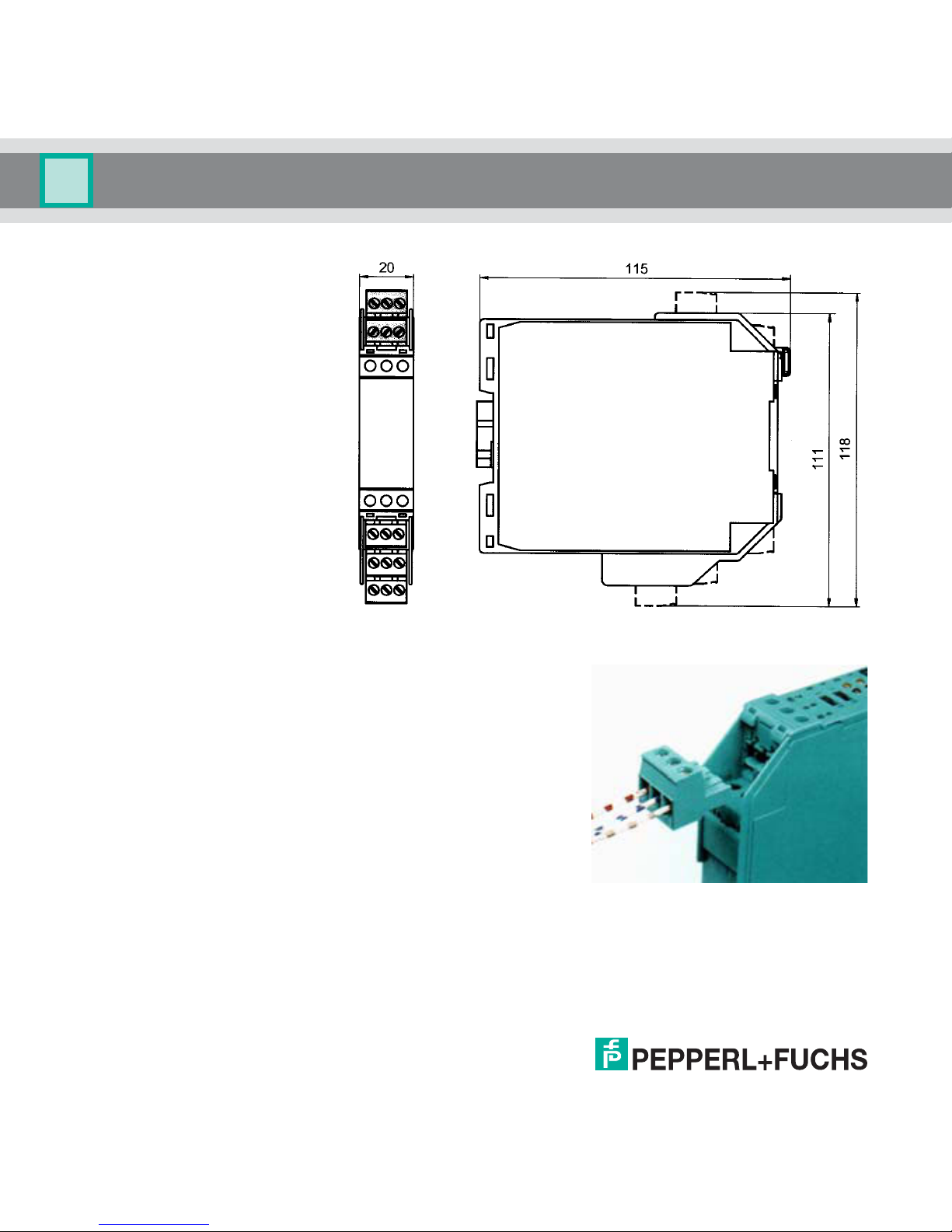
Mounting and Connection
Dimensions of the
Table of contents in mm
5.2 Connection
The KF series' slip-off terminals significantly simplify connection
and construction of switching cabinets. They allow quick and
error-free exchange of the unit when service is needed.
The terminals can be screwed on, are self-opening, and have
generous connection room for a wire diameter of up to 2.5 mm²
and coded plugs, so that leads cannot be confused.
6
284503 2015-09
Page 9

Temperature Trip Amplifier KFD2-GU-(Ex)1
1+
2- 3+
1-2- 3+
1-2- 3+ 4+
2- 5+
2- 6+
0 V ... 10 V
2 V ... 10 V
0 mA ... 20 mA
4 mA ... 20 mA
2-
Thermocouple
junction
compensation
Relay 1:
Relay 2:
789
10 11 12
K-CJC
Mounting and Connection
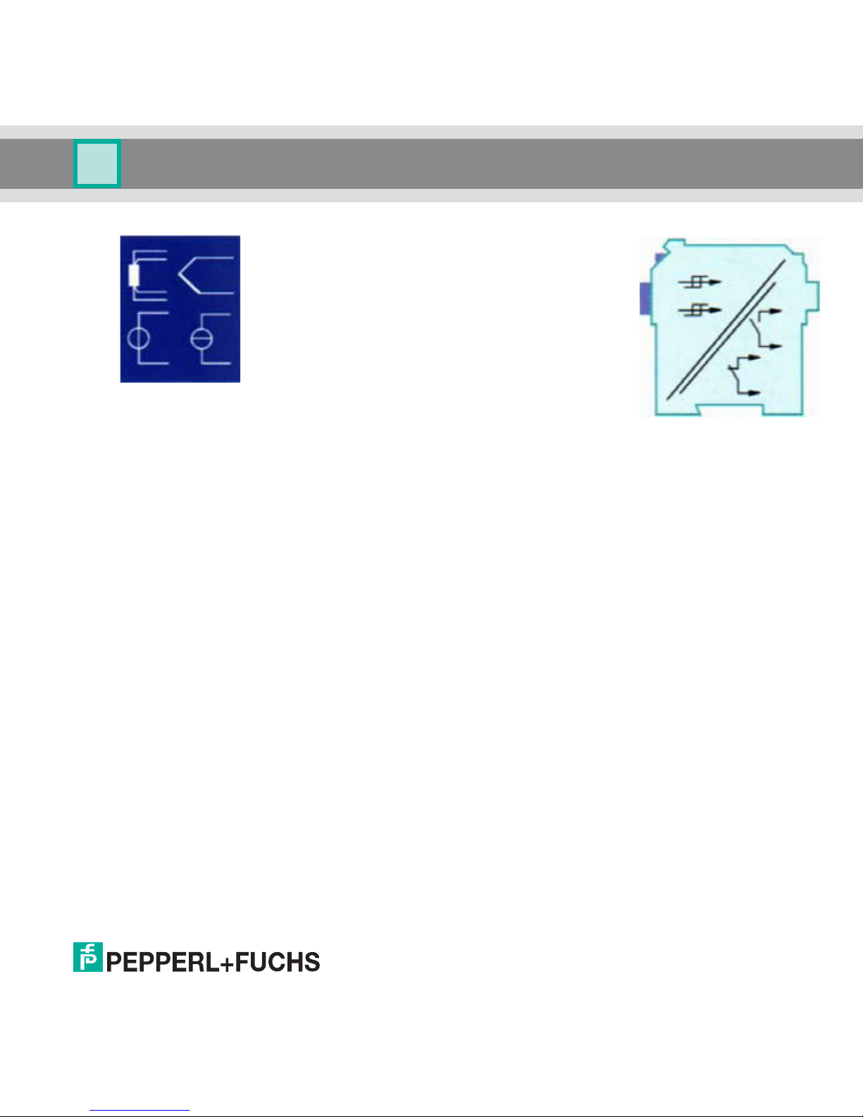
The intrinsically safe field circuit is connected to the blue
terminals 1 to 6 of the KFD2-GU-Ex1. The circuit can be
directed with interface cable based on EN 60079-14 into
the area subject to the danger of explosion.
The non-intrinsically safe field circuit is connected to the
green terminals 1 to 6 of the KFD2-GU-1.
In both cases you can connect:
• a resistance temperature sensor Pt100 or Ni100
in 2-wire design (terminals 2 and 3)
in 3-wire design (terminals 1 to 3)
in 4-wire design (terminals 1 to 4)
• a thermocouple of type B, E, J, K, L, N, R, S, or T
(terminals 1 and 2). For an internal cold junction
compensation, you will need terminal K-CJC as an
accessory instead of the normal terminal 1 to 3.
• a source for a unit current signal of 0 mA ... 20 mA or 4
mA ... 20 mA (terminals 2 and 5)
• a source for a unit voltage signal 0 V ... 10 V (terminals
2 and 6)
The function of the green terminals 7 to 15 is as follows:
• terminals 7 to 9: relay 1
• terminals 10 to 12: relay 2
• terminals 14(+)/15(-): 24 V DC power supply (13 free)
For power supply via Power Rail, please refer to the
"Interface Technology" catalog of Pepperl+Fuchs.
For a detailed account of the terminal assignments,
please refer to the data sheet.
284503 2015-09
7
Page 10

Temperature Trip Amplifier KFD2-GU-(Ex)1
PWR/FAULT
PROGRAM
OUT1
OUT2
Mounting and Connection
5.3 Operating and Indicating Elements
On the front of the GU you will find:
• LED OUT1 (yellow) for displaying relay 1 active
• LED OUT2 (yellow) for displaying relay 2 active
• LED PWR/FAULT (green/red) for displaying supply voltage
present/malfunction
• Interface for connecting a computer for parameterization
and diagnostics of the device with the PACTware
software, using the K-ADP-USB adapter
TM
operating
8
284503 2015-09
Page 11

Temperature Trip Amplifier KFD2-GU-(Ex)1
Note
Device Configuration via Software
6 Device Configuration via Software
The device is parameterised using the PACTwareTM operating software.
The PACTwareTM operating software and the necessary device and communication DTMs can be
downloaded from our internet page www.pepperl-fuchs.com (product search, enter PACTware).
The manual "Installation and Configuration DTM Collection Conventional Interface Introduction" guides
you through the installation steps necessary to install the software. The manual can be found on our
Internet page www.pepperl-fuchs.com (product search, enter PACTware).
In the following, you will find the device-specific information for the device.
6.1 Connection Between Device and Computer
Connect the device and the computer using the K-ADP-USB adapter. This adapter can be ordered as
an accessory.
Connecting the device to the computer via the USB interface
1. Mount the device as described in the system description.
2. Connect the device to the power supply as described in the system description.
3. Connect the device to the PC via the adapter with USB interface K-ADP-USB.
Connection on the device: front programming socket
Connection on the PC: USB interface
> The hardware wizard is displayed. Read the note.
4. Follow the installation instructions and confirm the installation steps.
> The installation completion window is displayed.
5. Confirm the end of the installation with Finish.
> The interface driver is installed.
The hardware wizard is displayed only on initial installation or for an update.
284503 2015-09
9
Page 12

Temperature Trip Amplifier KFD2-GU-(Ex)1
Device Configuration via Software
6.2 Communication Driver
In a PACTwareTM project, communication with the device is only possible via a communication driver. If
your project does not yet contain such a driver, please add it to the project from the device catalogue
(see manual).
The parameters of the communication DTM is the used PC interface and the number of retries.
The parameter is set as follows:
• Double-click the communication
driver with the mouse
• Select the Communication Port
• Communication Retries: number
of retries the COM DTM attempts
to establish communication to the
connected device.
To add a device to a project, select a
communication driver of the project.
Then add the device from the device
catalogue.
Further information on the individual
steps can be found in the manual.
The description in the following
chapters assume that a device has
been selected in the project.
10
284503 2015-09
Page 13

Temperature Trip Amplifier KFD2-GU-(Ex)1
Device Configuration via Software
6.3 Monitor Functions
If you have started the communication between PACTwareTM and the device (e. g. via Device data
Establish connection), you can open the Measured value window via Device data Measured value.
The following information is displayed:
• Measured value at the input as numerical value and bar graph, displayed in the selected unit.
•the status off both relays
284503 2015-09
11
Page 14

Temperature Trip Amplifier KFD2-GU-(Ex)1
Warning
Note
Device Configuration via Software
6.4 Simulation Function
If you have started the communication between PACTwareTM and the device (e. g. via Device data
Establish connection), you can open the Simulation window via Device data Simulation.
Simulation interrupts normal functionality of the device!
Before starting the simulation, make certain that this cannot result in any dangerous
state for the system .
The simulation mode is started with the check box Simulation Active.
12
You can assign the status for the two relays for test purposes:
de-energ ised = , energised =
Use the check box Simulation Active to end the simulation. The device returns to normal operation.
If the power supply is interrupted, the device ends the simulation.
• The relays assume the assigned status.
• During the simulation, the red LED on the front of the device flashes.
TM
• Devices in simulation mode are highlighted in PACTware
.
You can close the simulation window with the Close button or by clicking on the
Windows-standard button at the top right. The device will remain in simulation
mode, however, until the check box Simulation is deactivated.
284503 2015-09
Page 15

Temperature Trip Amplifier KFD2-GU-(Ex)1
Device Configuration via Software
6.5 Diagnosis
If you have started the communication between PACTwareTM and the device (e. g. via Device data
Establish connection), you can open the Diagnosis window via Device data Diagnosis. It shows the
following information:
284503 2015-09
Explanations:
• Sensor breakage: see section 7.2
• Sensor short circuit: only RTD type of sensor; see section 7.2
• Overrange, Underrange: measured variable outside the maximum measuring range of the selected
sensor (see section 7.2)
• CJC Error: if the cold junction compensation has been selected (see section 7.2) and a breakage or
short circuit occurs within the K-CJC terminal
• Simulation mode: see section 6.4
13
Page 16

Temperature Trip Amplifier KFD2-GU-(Ex)1
Warning
Working with Device Data
7 Working with Device Data
Any change made to the device date will change the functionality of the device!
Before transfer ring new da ta into th e devi ce , make cert ain that this cannot result in any
danger for the system .
If you select the PC-programming function for a device in PACTwareTM (see manual), a window with
menus for parameterization appears, these manues will be described as follows.
7.1 Menu Information and Description
The information on the Device info menu is generated automatically or is read from the device. This
information cannot be changed on the menu.
14
284503 2015-09
Page 17

Temperature Trip Amplifier KFD2-GU-(Ex)1
Working with Device Data
284503 2015-09
You can edit the text on the Description menu as you see fit and save it in the project file.
Tag Number Channel 1: freely selectable identification
15
Page 18

Temperature Trip Amplifier KFD2-GU-(Ex)1
Working with Device Data
7.2 Menu Parameter Input
16
284503 2015-09
Page 19

Temperature Trip Amplifier KFD2-GU-(Ex)1
Working with Device Data
The following parameters can be set:
•Sensor:
Resistance temperature measurement sensor: Pt100, Ni 00
Thermocouples: T/C type B, T/C type E, T/C type J, T/C type K, T/C type L, T/C type N,
T/C type R, T/C type S, T/C type T
other: 0...10 V, 0...20 mA, 4...20 mA (NE43)
• Connection mode (for resistance temperature detectors only, see section 5.2):
2-wire
3-wire
4-wire
• Unit:
for resistance temperature measurement sensors and termocouples: °C or K
with selection of 0...10 V under sensor: fixed V
with selection of 0...20 mA or 4...20 mA (NE43) under sensor: fixed mA
The unit selected at this point will be used for all corresponding settings and displays in PACTwareTM.
• Cold junction compensation (for thermocouples only):
external (Reference temperature)
internal (K-CJC)
If you have selected Ext. ref. temp., you can enter the external reference temperature
(range of values: -100 °C to 100 °C)
For a internal Cold junction compensation, you require the K-CJC terminal block as an accessory
instead of the normal terminal 1 to 3 or 4 to 6 (see section 5.2).
• Lead Resistance: When connecting an RTD with 2 wire connection the lead resistance of the cabling
can be entered numerically if known.
• 2-Wire Calibration: When connecting an RTD with 2 wire connection the lead resistance of the
cabling can be calibrated if the resistance is unknown. For calibration the sensor must be jumpered.
• Sensor-breakage monitoring (for all types of sensors)
• Sensor-short-circuit monitoring (for resistance temperature detectors only)
• Cold junction sensor defective (for thermocouples)
• Range exceeded (for 0...10 V and 0...20 mA)
284503 2015-09
17
Page 20

Temperature Trip Amplifier KFD2-GU-(Ex)1
Working with Device Data
• Value short of range lower limit (for 0...10 V )
You activate or deactivate monitoring by clicking the respective checkbox
( = selected, = deselected).
• Firmware Version: Here the Firmware Version of the device can be preselected. Depending on
Firmware Version some options and functions can differ. If the Firmware Version is unknown, this
can be entered automatically through an upload.
7.3 Menu Parameter Output
18
284503 2015-09
Page 21

Temperature Trip Amplifier KFD2-GU-(Ex)1
Working with Device Data
The following parameters can be set:
• Switching point and hysteresis for relay 1 and relay 2; the unit is displayed according to the selection
for Parameter Input (see section 7.2). The hysteresis should be selected as > 1 % of the
measurement range to avoid causing the relay to flutter.
• Switching direction (MAX or MIN) and mode of operation (energised or de-energised) for relay 1 and
relay 2
•The Error Output function for relay 2 is not available until firmware version 3.0.
• Alarm Freeze: when Alarm Freeze is selected, the Relay State is kept after trip or Fault Alarm until
the device is restarted (Power Off-On)
7.4 Switching Behaviour of the Relays
Available settings for the switching direction are MIN and MAX; available settings for the mode of
operation are energised and de-energised.
Range of application (see also figure on page 20):
• Switching direction MAX, mode of operation energised:
Alarm when limit value is exceeded, for example horn on
Protection against overheating, for example cooling on
• Switching direction MAX, mode of operation de-energised:
Protection against overheating, for example heater off;
with large hysteresis MIN-MAX operation, for example heater on/off
• Switching direction MIN, mode of operation energised:
Alarm when value falls short of lower limit, for example horn on
Protection against cooling too cold, for example heater on
• Switching direction MIN, mode of operation de-energised:
Protection against cooling off too cold, for example cooling off;
with large hysteresis MIN-MAX operation, for example cooling on/off
284503 2015-09
19
Page 22

Temperature Trip Amplifier KFD2-GU-(Ex)1
Time
Measurment value
MAX
MAX - hysteresis
MIN + hysteresis
MIN
Switching direction MAX, mode of operation energised:
energised
de-energised
Switching direction MAX, mode of operation de-energised:
energised
de-energised
Switching direction MIN, mode of operation energised:
energised
de-energised
Switching direction MIN, mode of operation de-energised:
energised
de-energised
Working with Device Data
Overview of switching behaviour of the relays:
20
284503 2015-09
Page 23

Temperature Trip Amplifier KFD2-GU-(Ex)1
Notes
284503 2015-09
21
Page 24

Subject to modifications
Copyright PEPPERL+FUCHS · Printed in Germany
www.pepperl-fuchs.com
Worldwide Headquarters
Pepperl+Fuchs GmbH
68307 Mannheim · Germany
Tel. +49 621 776-0
E-Mail: info@de.pepperl-fuchs.com
For the Pepperl+Fuchs representative
closest to you check www.pepperl-fuchs.com/contact
PROCESS AUTOMATION –
PROTECTING YOUR PROCESS
284503 DOCT-0150D
09/2015
 Loading...