

Page 1
Conductivity Switch Amplifier
KFD2-ER-1.6
1
2
3
7
8
9
24 V DC
11+
12-
Power Rail
24 V DC
100 %
0 %
Germany: +49 621 776 2222Pepperl+Fuchs Group
Refer to "General Notes Relating to Pepperl+Fuchs Product Information".
USA: +1 330 486 0002 Singapore: +65 6779 9091
www.pepperl-fuchs.com pa-info@us.pepperl-fuchs.com pa-info@sg.pepperl-fuchs.com
pa-info@de.pepperl-fuchs.com
KFD2-ER-1.6
1-channel signal conditioner
<
24 V DC supply (Power Rail)
<
Level sensing input
<
Adjustable range 5 kΩ ... 150 kΩ
<
Relay contact output
<
Minimum/maximum control
<
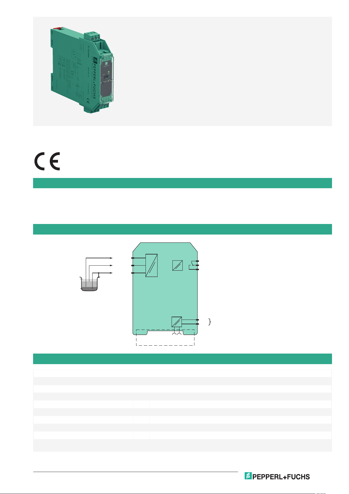
Function
This signal conditioner provides the AC measuring voltage for the levelsensing electrodes.
Once the measured medium reaches the electrodes, the unit reacts by energizing a form C changeover relay contact.
The module is voltage and temperature stabilized and guarantees defined switching characteristics. An electronic holding circuit is used that
allows minimum/maximum control. Since the conductance of the media may vary, the relay response sensitivity is adjustable.
The normal output state can be reversed through the mode of operation switch S1.
Connection
Technical Data
General specifications
Signal type Digital Input
Supply
Connection Power Rail or terminals 11+, 12-
Rated voltage U
Input
Connection side field side
Connection terminals 1 (mass), 2 (min), 3 (max)
Open circuit voltage/short-circuit current approx. 10 V AC (approx. 1 Hz) / approx. 5 mA
Control input min./max. control system: terminals 1, 2, 3
Release date: 2020-10-05 Date of issue: 2020-10-05 Filename: 096864_eng.pdf
r
20 ... 30 V DC
on/off control system: terminals 1, 3
1
Page 2
Conductivity Switch Amplifier KFD2-ER-1.6
Germany: +49 621 776 2222Pepperl+Fuchs Group
Refer to "General Notes Relating to Pepperl+Fuchs Product Information".
USA: +1 330 486 0002 Singapore: +65 6779 9091
www.pepperl-fuchs.com pa-info@us.pepperl-fuchs.com pa-info@sg.pepperl-fuchs.com
pa-info@de.pepperl-fuchs.com
Technical Data
Response sensitivity 5 ... 150 kΩ , adjustable via potentiometer (20 turns)
Output
Connection side control side
Connection terminals 7, 8, 9
Output 1 changeover contact
Contact loading 253 V AC/2 A/cos φ > 0.7; 40 V DC/2 A resistive load
Energized/De-energized delay approx. 1 s / approx. 1 s
Galvanic isolation
Input/Output reinforced insulation according to IEC/EN 61010-1, rated insulation voltage 300 V
Input/power supply reinforced insulation according to IEC/EN 61010-1, rated insulation voltage 300 V
Output/power supply reinforced insulation according to IEC/EN 61010-1, rated insulation voltage 300 V
Indicators/settings
Display elements LEDs
Control elements DIP-switch
potentiometer
Configuration via DIP switches
via potentiometer
Labeling space for labeling at the front
Directive conformity
Electromagnetic compatibility
Directive 2014/30/EU EN 61326-1:2013 (industrial locations)
Low voltage
Directive 2014/35/EU EN 61010-1:2010
Conformity
Electromagnetic compatibility NE 21:2006
Degree of protection IEC 60529:2001
Ambient conditions
Ambient temperature -20 ... 60 °C (-4 ... 140 °F)
Mechanical specifications
Degree of protection IP20
Connection screw terminals , max. 2.5 mm
2
Mass approx. 110 g
Dimensions 20 x 107 x 115 mm (0.8 x 4.2 x 4.5 inch) , housing type B1
Mounting on 35 mm DIN mounting rail acc. to EN 60715:2001
Indication and operation
Control elements switch S1
Position I open circuit current: In the open circuit current principle, the relay becomes
active when the limit is reached.
Position II closed circuit current: In closed circuit current principle, the relay is activated
when power is applied. The relay is deactivated when the limit is reached.
General information
Supplementary information Statement of Conformity, Declaration of Conformity, Attestation of Conformity and
instructions have to be observed where applicable. For information see www.pepperlfuchs.com.
eff
eff
eff
Release date: 2020-10-05 Date of issue: 2020-10-05 Filename: 096864_eng.pdf
2
Page 3

12
9
10
7
11
8
1
3
4
6
2
5
KFD2-ER-1.6
S1
I II
OUT PWR
SENSITIVITY
LED yellow:
Relay output
LED green:
Power supply
Removable terminals
green
Removable terminal
green
Potentiometer
Response sensitivity
Front view
Switch S1
Mode of operation
Conductivity Switch Amplifier KFD2-ER-1.6
Germany: +49 621 776 2222Pepperl+Fuchs Group
Refer to "General Notes Relating to Pepperl+Fuchs Product Information".
USA: +1 330 486 0002 Singapore: +65 6779 9091
www.pepperl-fuchs.com pa-info@us.pepperl-fuchs.com pa-info@sg.pepperl-fuchs.com
pa-info@de.pepperl-fuchs.com
Assembly
Matching system components
KFD2-EB2 Power Feed Module
UPR-03 Universal Power Rail with end caps and cover, 3 conductors, length: 2 m
UPR-03-M Universal Power Rail with end caps and cover, 3 conductors, length: 1,6 m
UPR-03-S Universal Power Rail with end caps and cover, 3 conductors, length: 0.8 m
K-DUCT-GY
K-DUCT-GY-UPR-03 Profile rail with UPR-03-* insert, 3 conductors, wiring comb field side gray
Accessories
KF-ST-5GN
Release date: 2020-10-05 Date of issue: 2020-10-05 Filename: 096864_eng.pdf
3
 Loading...