

Page 1
Transmitter Power Supply
2
Zone 2
Div. 2
Zone 0, 1, 2
Div. 1, 2
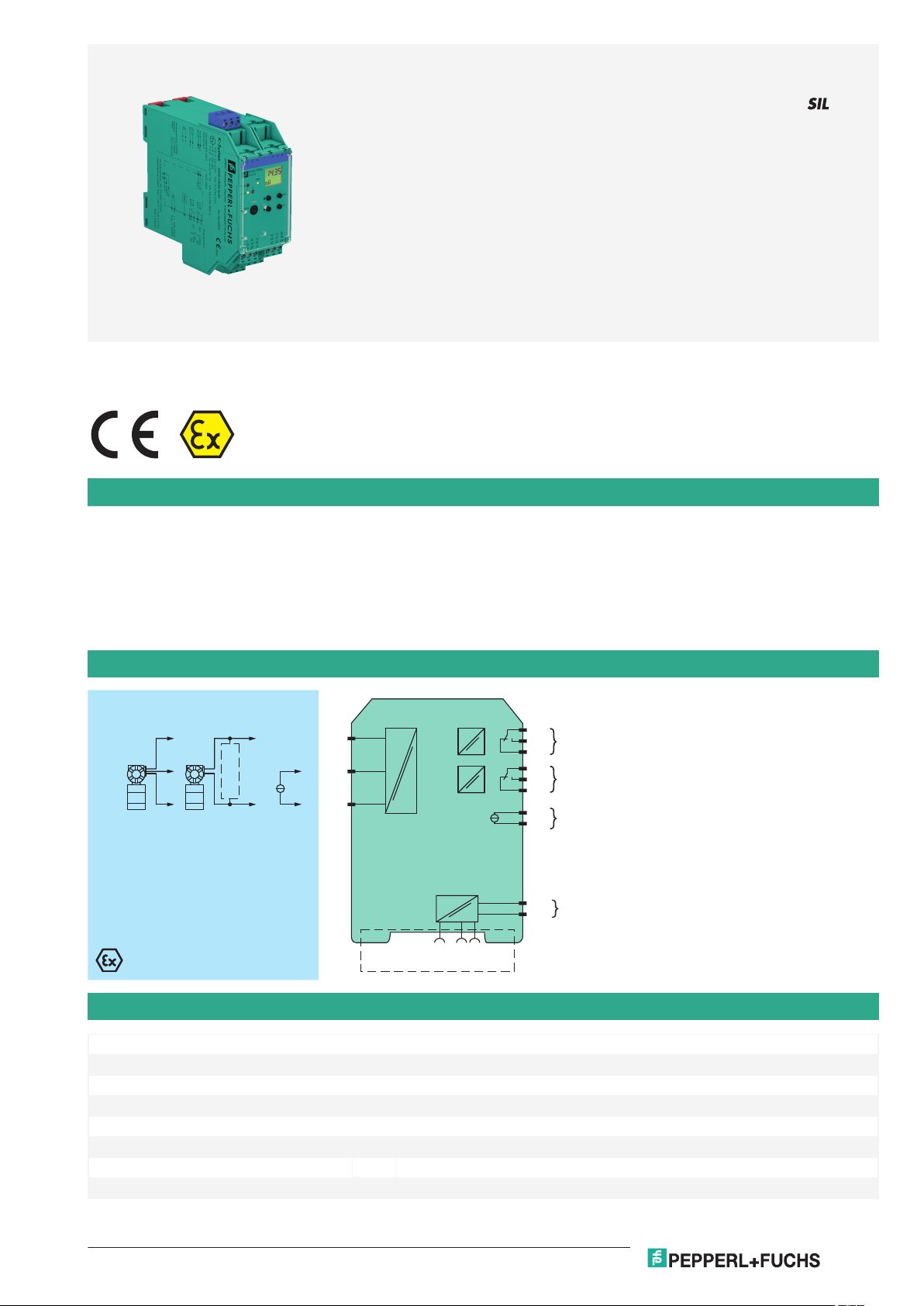
KFD2-CRG2-Ex1.D
16
17
18
10
11
12
I
II
III
78+
24 V DC
23+
24-
Power Rail
24 V DCFault
3
1+
2-
mA
mA
HART
Germany: +49 621 776 2222Pepperl+Fuchs Group
Refer to "General Notes Relating to Pepperl+Fuchs Product Information".
USA: +1 330 486 0002 Singapore: +65 6779 9091
www.pepperl-fuchs.com pa-info@us.pepperl-fuchs.com pa-info@sg.pepperl-fuchs.com
pa-info@de.pepperl-fuchs.com
KFD2-CRG2-Ex1.D
1-channel isolated barrier
<
24 V DC supply (Power Rail)
<
Input 2-wire and 3-wire transmitters and 2-wire current sources
<
Output 0/4 mA ... 20 mA
<
2 relay contact outputs
<
Adjustable energized/de-energized delay
<
Programmable high/low alarm
<
Linearization function (max 20 points)
<
Line fault detection (LFD)
<
Up to SIL 2 acc. to IEC 61508/IEC 61511
<
Function
This isolated barrier is used for intrinsic safety applications.
The device supplies 2-wire and 3-wire transmitters, and can also be used with current sources.
Two relays and an active 0/4 mA ... 20 mA current source are available as outputs. The relay contacts and the current output can be integrated in
security-relevant circuits. The current output is easily scaled.
On the display the measured value can be indicated in various physical units.
The device is easily configured by the use of keypad or with the PACTware configuration software.
The input has a line fault detection.
A fault is signalized by LEDs acc. to NAMUR NE44 and a separate collective error message output.
For additional information, refer to the manual and www.pepperl-fuchs.com.
Connection
Technical Data
General specifications
Signal type Analog input
Functional safety related parameters
Safety Integrity Level (SIL) SIL 2
Supply
Connection Power Rail or terminals 23+, 24Rated voltage U
Rated current I
Release date: 2020-09-23 Date of issue: 2020-09-23 Filename: 255620_eng.pdf
r
r
20 ... 30 V DC
approx. 130 mA
1
Page 2

Transmitter Power Supply KFD2-CRG2-Ex1.D
Germany: +49 621 776 2222Pepperl+Fuchs Group
Refer to "General Notes Relating to Pepperl+Fuchs Product Information".
USA: +1 330 486 0002 Singapore: +65 6779 9091
www.pepperl-fuchs.com pa-info@us.pepperl-fuchs.com pa-info@sg.pepperl-fuchs.com
pa-info@de.pepperl-fuchs.com
Technical Data
Power dissipation 2 W
Power consumption 2.5 W
Interface
Programming interface programming socket
Input
Connection side field side
Connection terminals 1, 2, 3
Input I
Input signal 0/4 ... 20 mA
Available voltage ≥ 15 V at 20 mA
Open circuit voltage/short-circuit current 24 V / 33 mA
Input resistance 45 Ω (terminals 2, 3)
Line fault detection breakage I < 0.2 mA; short-circuit I > 22 mA
Output
Connection side control side
Connection output I: terminals 10, 11, 12
Output signal 0 ... 20 mA or 4 ... 20 mA
Output I, II signal, relay
Contact loading 250 V AC / 2 A / cos φ ≥ 0.7 ; 40 DC / 2 A
Mechanical life 5 x 10⁷ switching cycles
Output III Signal, analog
Current range 0 ... 20 mA or 4 ... 20 mA
Open loop voltage max. 24 V DC
Load max. 650 Ω
Fault signal downscale I ≤ 3.6 mA, upscale I ≥ 21 mA (acc. NAMUR NE43)
Energized/De-energized delay 0 ... 250 s , adjustable
Transfer characteristics
Input I
Accuracy < 30 µA
Influence of ambient temperature 0.003 %/K (30 ppm)
Output I, II
Response delay ≤ 200 ms at bounce from 0 ... 20 mA
Output III
Resolution ≤ 10 µA
Accuracy < 20 µA
Influence of ambient temperature 0.005 %/K (50 ppm)
Reaction time < 650 ms at bounce from 0 ... 20 mA at the input, 90 % of output full-scale value
Galvanic isolation
Input/Other circuits reinforced insulation according to IEC/EN 61010-1, rated insulation voltage 300 V
Output I, II/other circuits reinforced insulation according to IEC/EN 61010-1, rated insulation voltage 300 V
Mutual output I, II, III reinforced insulation according to IEC/EN 61010-1, rated insulation voltage 300 V
Output III/power supply and collective error functional insulation acc. to IEC 62103, rated insulation voltage 50 V
Interface/power supply and collective error functional insulation acc. to IEC 62103, rated insulation voltage 50 V
Indicators/settings
Display elements LEDs , display
Control elements Control panel
Configuration via operating buttons
Labeling space for labeling at the front
Directive conformity
Electromagnetic compatibility
Directive 2014/30/EU EN 61326-1:2013 (industrial locations)
Release date: 2020-09-23 Date of issue: 2020-09-23 Filename: 255620_eng.pdf
output II: terminals 16, 17, 18
output III: terminals 8+, 7-
eff
eff
via PACTware
eff
eff
eff
2
Page 3
Transmitter Power Supply KFD2-CRG2-Ex1.D
Germany: +49 621 776 2222Pepperl+Fuchs Group
Refer to "General Notes Relating to Pepperl+Fuchs Product Information".
USA: +1 330 486 0002 Singapore: +65 6779 9091
www.pepperl-fuchs.com pa-info@us.pepperl-fuchs.com pa-info@sg.pepperl-fuchs.com
pa-info@de.pepperl-fuchs.com
Technical Data
Low voltage
Directive 2014/35/EU EN 61010-1:2010
Conformity
Electromagnetic compatibility NE 21:2006
Degree of protection IEC 60529:2001
Ambient conditions
Ambient temperature -20 ... 60 °C (-4 ... 140 °F)
Mechanical specifications
Degree of protection IP20
Connection screw terminals
Mass 300 g
Dimensions 40 x 119 x 115 mm (1.6 x 4.7 x 4.5 inch) , housing type C3
Mounting on 35 mm DIN mounting rail acc. to EN 60715:2001
Data for application in connection with hazardous areas
EU-Type Examination Certificate TÜV 01 ATEX 1701
Marking 1 II (1)G [Ex ia Ga] IIC
Input Ex ia
Supply
Maximum safe voltage U
Equipment terminals 1+, 3-
Voltage U
Current I
Power P
o
o
o
Equipment terminals 2-, 3
Voltage U
Current I
Voltage U
Current I
Power P
i
i
o
o
o
Equipment terminals 1+, 2 / 3-
Voltage U
Current I
Power P
o
o
o
Output I, II terminals 10, 11, 12; 16, 17, 18 non-intrinsically safe
Maximum safe voltage U
Contact loading 253 V AC/2 A/cos φ > 0.7; 40 V DC/2 A resistive load (TÜV 01 ATEX 1701)
1 II (1)D [Ex ia Da] IIIC
1 I (M1) [Ex ia Ma] I
40 V DC (Attention! The rated voltage can be lower.)
m
25.8 V
93 mA
0.603 W
< 30 V
115 mA
5 V
0.3 mA
0.3 mW
25.8 V
112 mA
720 mW
253 V AC / 40 V DC (Attention! Um is no rated voltage.)
m
Output III terminals 8+, 7- non-intrinsically safe
Maximum safe voltage U
m
U
40 V (Attention! The rated voltage can be lower.)
m
Interface RS 232
Maximum safe voltage U
40 V (Attention! The rated voltage can be lower.) , RS 232
m
Certificate TÜV 02 ATEX 1885 X
Marking 1 II 3G Ex nA nC IIC T4
Output I, II
Contact loading 50 V AC/2 A/cos φ > 0.7; 40 V DC/1 A resistive load
Galvanic isolation
Input/Other circuits safe electrical isolation acc. to IEC/EN 60079-11, voltage peak value 375 V
Directive conformity
Directive 2014/34/EU EN 60079-0:2012+A11:2013 , EN 60079-11:2012 , EN 60079-15:2010
International approvals
FM approval
Control drawing 16-554FM-12 (cFMus)
Release date: 2020-09-23 Date of issue: 2020-09-23 Filename: 255620_eng.pdf
3
Page 4

ESC
OK
KFD2-CRG2Ex1.D
RS232
PWR
1 2
FLT
OUT
19 21
15
9
13
7
20
14
8
22 24
18
12
16
10
23
17
11
132 465
Front view
Removable terminals
green
Removable terminal
blue
Keypad
LC display
LED green:
Power supply
Programming jack
Place for labeling
LED red:
Fault signal
LED yellow:
Output II
LED yellow:
Output I
Transmitter Power Supply KFD2-CRG2-Ex1.D
Germany: +49 621 776 2222Pepperl+Fuchs Group
Refer to "General Notes Relating to Pepperl+Fuchs Product Information".
USA: +1 330 486 0002 Singapore: +65 6779 9091
www.pepperl-fuchs.com pa-info@us.pepperl-fuchs.com pa-info@sg.pepperl-fuchs.com
pa-info@de.pepperl-fuchs.com
Technical Data
UL approval E223772
IECEx approval IECEx TUN 09.0007
Approved for [Ex ia Ga] IIC, [Ex ia Da] IIIC, [Ex ia Ma] I
General information
Supplementary information Observe the certificates, declarations of conformity, instruction manuals, and manuals
where applicable. For information see www.pepperl-fuchs.com.
Accessories
Optional accessories - power feed module KFD2-EB2(.R4A.B)(.SP)
- universal power rail UPR-03(-M)(-S)
- profile rail K-DUCT-BU(-UPR-03)
- FDT framework PACTware 4.1
- device type manager DTM Interface Technology
- adapter K-ADP-USB
Assembly
Accessories
DTM Interface
Technology
KFD2-EB2 Power Feed Module
KFD2-EB2.R4A.B Power feed module, redundant supply
KFD2-EB2.R4A.B.SP Power feed module with spring terminals, redundant supply
KFD2-EB2.SP Power feed module with spring terminals
UPR-03 Universal Power Rail with end caps and cover, 3 conductors, length: 2 m
Release date: 2020-09-23 Date of issue: 2020-09-23 Filename: 255620_eng.pdf
4
Page 5

Transmitter Power Supply KFD2-CRG2-Ex1.D
Germany: +49 621 776 2222Pepperl+Fuchs Group
Refer to "General Notes Relating to Pepperl+Fuchs Product Information".
USA: +1 330 486 0002 Singapore: +65 6779 9091
www.pepperl-fuchs.com pa-info@us.pepperl-fuchs.com pa-info@sg.pepperl-fuchs.com
pa-info@de.pepperl-fuchs.com
Accessories
UPR-03-M Universal Power Rail with end caps and cover, 3 conductors, length: 1,6 m
UPR-03-S Universal Power Rail with end caps and cover, 3 conductors, length: 0.8 m
K-DUCT-BU
K-DUCT-BU-UPR-03 Profile rail with UPR-03- * insert, 3 conductors, wiring comb field side blue
K-ADP-USB
PACTware 5.X FDT Framework
Release date: 2020-09-23 Date of issue: 2020-09-23 Filename: 255620_eng.pdf
5
Page 6

Germany: +49 621 776 2222Pepperl+Fuchs Group
Refer to "General Notes Relating to Pepperl+Fuchs Product Information".
USA: +1 330 486 0002 Singapore: +65 6779 9091
www.pepperl-fuchs.com pa-info@us.pepperl-fuchs.com pa-info@sg.pepperl-fuchs.com
pa-info@de.pepperl-fuchs.com
Transmitter Power Supply
0.1
1
0.2
0.15
2
0.3
3
0.4
4
0.5
0 50 150 200 250100
I (A)
U (V)
1
Characteristic Curve
Maximum Switching Power of Output Contacts
Resistive load DC
Resistive load AC
1 max. 105 switching cycles
KFD2-CRG2-Ex1.D
Release date: 2020-09-23 Date of issue: 2020-09-23 Filename: 255620_eng.pdf
6
 Loading...