

Pepperl+Fuchs KFD, KFD2-HMM-16, KFD0-HMS-16 Series Manual
3
PROCESS AUTOMATION
MANUAL
HART Multiplexer
System
KFD*-HM*-16
ISO9001

HART Multiplexer System KFD*-HM*-16
With regard to the supply of products, the current issue of the following document is applicable: The General Terms of
Delivery for Products and Services of the Electrical Industry, published by the Central Association of the Electrical
Industry (Zentralverband Elektrotechnik und Elektroindustrie (ZVEI) e.V.) in its most recent version as well as the
supplementary clause: "Expanded reservation of proprietorship"

HART Multiplexer System KFD*-HM*-16
Content
1 Introduction . . . . . . . . . . . . . . . . . . . . . . . . . . . . . . . . . . . . . . . . . . . . . . . . . . . 5
1.1 Manufacturer . . . . . . . . . . . . . . . . . . . . . . . . . . . . . . . . . . . . . . . . . . . . . . . 5
1.2 Content of this Document. . . . . . . . . . . . . . . . . . . . . . . . . . . . . . . . . . . . . 5
1.3 Target Group, Personnel . . . . . . . . . . . . . . . . . . . . . . . . . . . . . . . . . . . . . 6
1.4 Symbols Used . . . . . . . . . . . . . . . . . . . . . . . . . . . . . . . . . . . . . . . . . . . . . . 6
2 Product Specifications . . . . . . . . . . . . . . . . . . . . . . . . . . . . . . . . . . . . . . . . . . 7
2.1 Device Versions . . . . . . . . . . . . . . . . . . . . . . . . . . . . . . . . . . . . . . . . . . . . . 7
2.2 Function . . . . . . . . . . . . . . . . . . . . . . . . . . . . . . . . . . . . . . . . . . . . . . . . . . . 7
3 System Description . . . . . . . . . . . . . . . . . . . . . . . . . . . . . . . . . . . . . . . . . . . . 10
3.1 The Basic Principles of HART Communication . . . . . . . . . . . . . . . . . . 10
3.2 Possible Applications . . . . . . . . . . . . . . . . . . . . . . . . . . . . . . . . . . . . . . . 11
3.3 Integration into Operating Software . . . . . . . . . . . . . . . . . . . . . . . . . . . 12
3.4 System Structure. . . . . . . . . . . . . . . . . . . . . . . . . . . . . . . . . . . . . . . . . . . 12
4 Mounting and Installation . . . . . . . . . . . . . . . . . . . . . . . . . . . . . . . . . . . . . . . 16
4.1 DIN Mounting Rail . . . . . . . . . . . . . . . . . . . . . . . . . . . . . . . . . . . . . . . . . . 16
4.2 Power Rail . . . . . . . . . . . . . . . . . . . . . . . . . . . . . . . . . . . . . . . . . . . . . . . . 17
4.3 Mounting. . . . . . . . . . . . . . . . . . . . . . . . . . . . . . . . . . . . . . . . . . . . . . . . . . 18
4.4 Connecting the Multiplexer Master . . . . . . . . . . . . . . . . . . . . . . . . . . . . 19
4.5 Connecting the Multiplexer Slaves . . . . . . . . . . . . . . . . . . . . . . . . . . . . 23
4.6 Connecting the Termination Board . . . . . . . . . . . . . . . . . . . . . . . . . . . . 26
4.7 Information Regarding Electromagnetic Compatibility . . . . . . . . . . . 27
5 Commissioning . . . . . . . . . . . . . . . . . . . . . . . . . . . . . . . . . . . . . . . . . . . . . . . 28
5.1 Data Access to the Connected Field Devices . . . . . . . . . . . . . . . . . . . 28
5.2 Configuration of the Multiplexer Master. . . . . . . . . . . . . . . . . . . . . . . . 28
2018-04
3

HART Multiplexer System KFD*-HM*-16
Content
6 Configuration . . . . . . . . . . . . . . . . . . . . . . . . . . . . . . . . . . . . . . . . . . . . . . . . . 33
6.1 Introduction to PACTware Operating Software. . . . . . . . . . . . . . . . . . 33
6.2 Software Components . . . . . . . . . . . . . . . . . . . . . . . . . . . . . . . . . . . . . . 34
6.3 PACTware Main Window . . . . . . . . . . . . . . . . . . . . . . . . . . . . . . . . . . . . 36
6.4 Connecting with the Device . . . . . . . . . . . . . . . . . . . . . . . . . . . . . . . . . 38
6.5 Inserting the Communication DTM . . . . . . . . . . . . . . . . . . . . . . . . . . . . 39
6.6 Inserting the Multiplexer Devices . . . . . . . . . . . . . . . . . . . . . . . . . . . . . 42
6.7 Displaying Device Information and Setting Parameters . . . . . . . . . . 44
6.8 HART Scan . . . . . . . . . . . . . . . . . . . . . . . . . . . . . . . . . . . . . . . . . . . . . . . . 52
6.9 Adding DTMs Manually . . . . . . . . . . . . . . . . . . . . . . . . . . . . . . . . . . . . . 61
7 Operation . . . . . . . . . . . . . . . . . . . . . . . . . . . . . . . . . . . . . . . . . . . . . . . . . . . . 62
7.1 Device Functions. . . . . . . . . . . . . . . . . . . . . . . . . . . . . . . . . . . . . . . . . . . 62
7.2 Software Functions. . . . . . . . . . . . . . . . . . . . . . . . . . . . . . . . . . . . . . . . . 65
7.3 Diagnosis and Troubleshooting . . . . . . . . . . . . . . . . . . . . . . . . . . . . . . 72
8 Dismounting, Maintenance, and Repair . . . . . . . . . . . . . . . . . . . . . . . . . . . 78
9 Appendix. . . . . . . . . . . . . . . . . . . . . . . . . . . . . . . . . . . . . . . . . . . . . . . . . . . . . 80
9.1 Supported HART Commands . . . . . . . . . . . . . . . . . . . . . . . . . . . . . . . . 80
9.2 Assignment of the 26-Pin IDC Socket with Analog HART Signals . . 84
9.3 Bibliography . . . . . . . . . . . . . . . . . . . . . . . . . . . . . . . . . . . . . . . . . . . . . . 85
9.4 Glossary . . . . . . . . . . . . . . . . . . . . . . . . . . . . . . . . . . . . . . . . . . . . . . . . . . 86
2018-04
4
HART Multiplexer System KFD*-HM*-16
Introduction
1Introduction
1.1 Manufacturer
Pepperl+Fuchs GmbH
Lilienthalstraße 200, 68307 Mannheim, Germany
Internet: www.pepperl-fuchs.com
1.2 Content of this Document
This document contains information that you need in order to use your product throughout
the applicable stages of the product life cycle. These can include the following:
• Product identification
• Delivery, transport, and storage
• Mounting and installation
• Commissioning and operation
• Maintenance and repair
• Troubleshooting
• Dismounting
• Disposal
Note!
This document does not substitute the instruction manual.
Note!
For full information on the product, refer to the instruction manual and further documentation
on the Internet at www.pepperl-fuchs.com.
The documentation consists of the following parts:
• Present document
• Instruction manual
•Datasheet
Additionally, the following parts may belong to the documentation, if applicable:
• EU-type examination certificate
• EU declaration of conformity
• Attestation of conformity
• Certificates
• Control drawings
• Additional documents
2018-04
5
HART Multiplexer System KFD*-HM*-16
Introduction
1.3 Target Group, Personnel
Responsibility for planning, assembly, commissioning, operation, maintenance,
and dismounting lies with the plant operator.
Only appropriately trained and qualified personnel may carry out mounting, installation,
commissioning, operation, maintenance, and dismounting of the product. The personnel must
have read and understood the instruction manual and the further documentation.
Prior to using the product make yourself familiar with it. Read the document carefully.
1.4 Symbols Used
This document contains symbols for the identification of warning messages and of
informative messages.
Warning Messages
You will find warning messages, whenever dangers may arise from your actions.
It is mandatory that you observe these warning messages for your personal safety and in order
to avoid property damage.
Depending on the risk level, the warning messages are displayed in descending order
as follows:
Danger!
This symbol indicates an imminent danger.
Non-observance will result in personal injury or death.
Warning!
This symbol indicates a possible fault or danger.
Non-observance may cause personal injury or serious property damage.
Caution!
This symbol indicates a possible fault.
Non-observance could interrupt the device and any connected systems and plants,
or result in their complete failure.
Informative Symbols
Note!
This symbol brings important information to your attention.
Action
This symbol indicates a paragraph with instructions. You are prompted to perform an action
or a sequence of actions.
2018-04
6

HART Multiplexer System KFD*-HM*-16
Product Specifications
2 Product Specifications
2.1 Device Versions
This manual describes the following devices:
• HART multiplexer master KFD2-HMM-16, hereinafter referred to as the multiplexer master
• HART multiplexer slave KFD0-HMS-16, hereinafter referred to as the multiplexer slave
2.2 Function
The HART multiplexer system consists of one HART multiplexer master KFD2-HMM-16 and
several HART multiplexer slaves KFD0-HMS-16. The HART multiplexer system is used
to establish a HART connection to analog field devices and thereby maintain the conventional
analog 4 mA to 20 mA circuits. The devices of the HART multiplexer system act as gateways
between the field devices and the control side.
The devices of the HART multiplexer system can be used in the Zone 2 hazardous area or
in the non-hazardous area. The devices are supplied with 24 VDC. The devices are connected
to a maintenance station or the process control system via an RS-485 interface.
The supply, the analog signals, and the RS-485 interface are galvanically isolated from each
other. The individual HART channels are decoupled. This does not affect
the 4 mA to 20 mA signal.
Using the configuration software, you can search for available field devices automatically and
query the HART variables of the field devices automatically.
2018-04
7
HART Multiplexer System KFD*-HM*-16
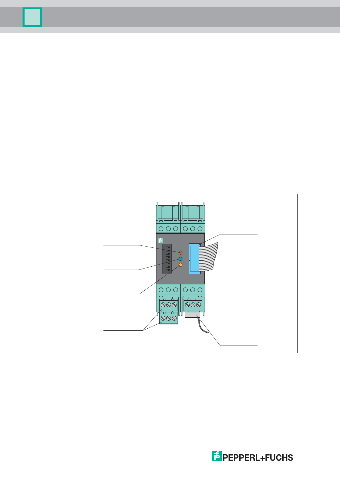
1
2
3
4
5
6
7
8
19
17131816
201421
15
KFD0-HMM-16
1
26
26-pin connector
LED orange:
Operation
14-pin connector
Removable terminals
green
LED red:
Fault signal
LED green:
Power supply
Product Specifications
2.2.1 HART Multiplexer Master KFD2-HMM-16
In addition to the master unit, the multiplexer master has an integrated slave unit. A maximum
of 16 field devices can be connected to this slave unit. If more than 16 field devices have
to be connected, a maximum of 15 additional HART multiplexer slaves KFD0-HMS-16 can
be connected to the multiplexer master. This enables a maximum of 256 analog field devices
to be connected to the HART multiplexer system.
The device is supplied with power via the Power Rail or via terminals.
The device is connected to a maintenance station via the RS-485 interface. You can connect
additional participants via an additional RS-485 interface. The transfer rate is max.
57600 baud.
The device is connected to the multiplexer slaves via a 14-pin ribbon cable. The device has
a 14-pin IDC socket on the bottom of the device for this purpose.
The device is connected to the termination board via a 26-pin ribbon cable. The device has
a 26-pin IDC socket on the front of the device for this purpose.
The device can be used as a primary or secondary master.
The device address and the transfer rate are set via DIP switch.
8
Figure 2.1 Assembly of the KFD2-HMM-16 HART multiplexer master
2018-04
HART Multiplexer System KFD*-HM*-16
KFD0-HMS-16
1
26
Rotary switch
26 pin
connector
14 pin
connector
Product Specifications
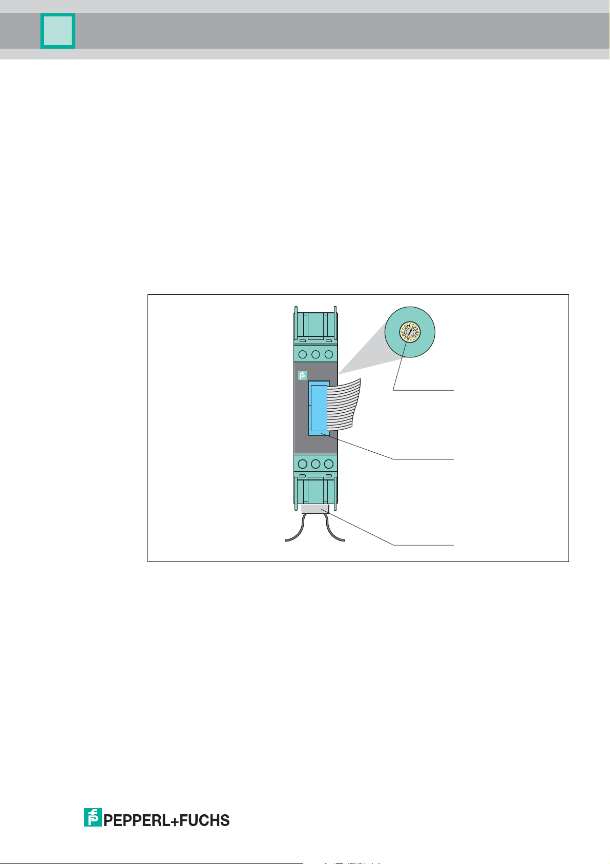
2.2.2 HART Multiplexer Slave KFD0-HMS-16
A maximum of 16 analog field devices can be connected to the multiplexer slave. The device
can only be used in conjunction with the HART multiplexer master KFD2-HMM-16.
The device is supplied with power by the multiplexer master via the 14-pin ribbon cable.
The device is connected with the multiplexer master and additional multiplexer slaves
via a 14-pin ribbon cable. The device has a 14-pin IDC socket on the bottom of the device for
this purpose.
The device is connected to the termination board via a 26-pin ribbon cable.
The device has a 26-pin IDC socket on the front of the device for this purpose.
The device address is set using a rotary switch. You can assign addresses 1 to 15.
The address 0 is reserved for the multiplexer master and may therefore not be used. If several
multiplexer slaves are connected to the multiplexer master, different addresses must
be assigned. The sequence is irrelevant.
2018-04
Figure 2.2 Assembly of the KFD0-HMS-16 HART multiplexer slave
9
HART Multiplexer System KFD*-HM*-16
+0.5 mA
-0.5 mA
0
1200 Hz 2200 Hz
"1"
"0"
20 mA
4 mA
Analog
signal
C = Command
R = Response
Time (seconds)
HART signal
C
R
C
R
C
R
System Description
3 System Description
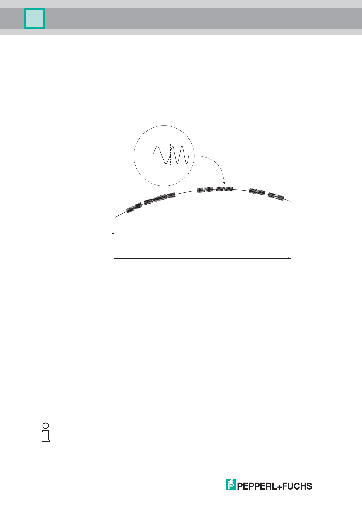
3.1 The Basic Principles of HART Communication
The HART protocol is supported by many conventional 4mAto20mA field devices that use it
to enable digital communication for configuration and maintenance purposes. Many of the
device parameters, and the measured value itself, can be digitally transferred to and from
the device. This digital communication runs in parallel to the 4 mA to 20 mA signal on the same
line. This is enabled via current modulation, which is superimposed on the desired signal.
Figure 3.1
The high-frequency HART signal consists of the sine frequencies 1200 Hz and 2200 Hz.
The average value of the signal is 0 and can therefore be filtered through the standard circuit of
the analog input. This does not affect the analog signal.
The HART protocol is a master-slave protocol. This means that a field device responds only
when it is addressed. Burst mode is an exception. The message duration is a few hundred
milliseconds, meaning that two to three messages can be transferred per second.
The HART commands are divided into 3 groups:
• Universal commands
These commands must be supported by all field devices.
• Common practice commands
These commands correspond to common practice and are suitable for many field devices.
• Device-specific commands
These commands are only suitable for certain field devices.
All three types of commands are used in the HART multiplexer system. This document
includes a list of commands. See chapter 9.1.
Note!
Additional information can be found in /1/, /2/, /3/, see chapter 9.3.
2018-04
10
HART Multiplexer System KFD*-HM*-16
System Description
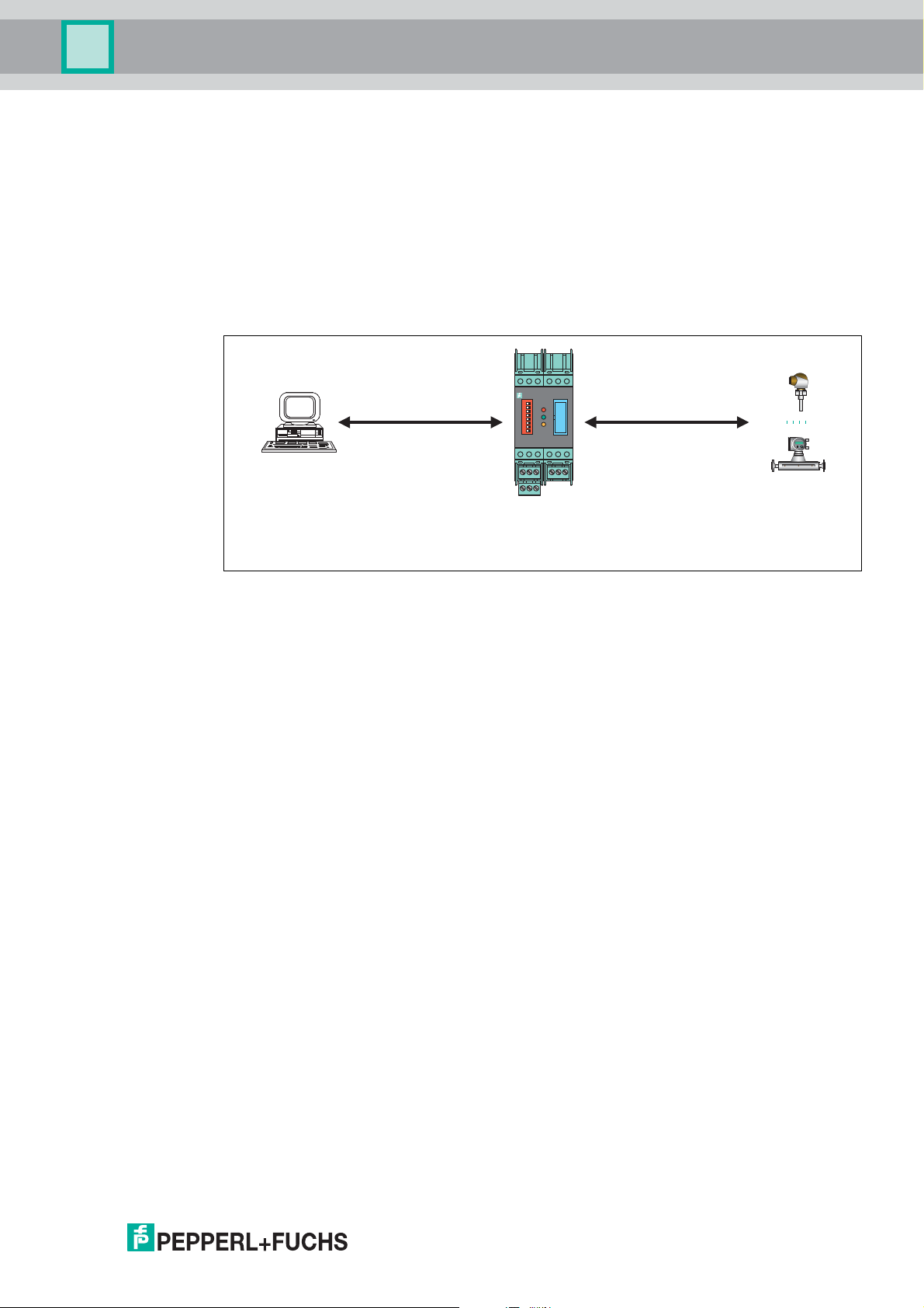
3.2 Possible Applications
General Applications
In process engineering plants, many field devices are distributed over a large area.
The characteristic values of these field devices must be monitored and logged or adjusted if
process variables are changed.
The HART multiplexer system from Pepperl+Fuchs enables communication between a
computer or a process control system and field devices that support the HART protocol.
The following figure shows the basic system structure.
HART communication 1 HART communication 2
19
KFD0-HMM-16
1
2
3
4
5
6
7
8
1713 181620142115
Host
Computer-based
maintenance station
or process control system
HART multiplexer system
Field devices
Figure 3.2 Basic structure
HART-compatible field devices allow information such as the measuring range and device
address to be saved in the field device itself. Access to this data is usually achieved with a
handheld. This means that a connection to the field device must be established manually for
each value to be changed.
If certain data has to be logged as part of quality assurance processes, this increases the effort
for the process control system. For example, the relevant data has to be requested cyclically
and saved in a database by the system.
The HART multiplexer system establishes the connection between the computer and the
HART-compatible field devices. All access to the field device takes place parallel to the
transmission of the 4 mA to 20 mA signal and therefore has no affect on the processing of
measured values by the process control system.
The system provides a subordinate service level. The HART multiplexer system can also
detect measured values. For field devices that are mounted in hazardous areas,
the connection takes place on the non-hazardous side of the control unit.
Pepperl+Fuchs offers corresponding control units, e. g., KCD2-STC-**, KCD2-SCD-**.
The HART multiplexer system can also be connected to control units from other
manufacturers. Existing plants can therefore be extended very easily, taking full advantage of
the HART communication.
2018-04
The system can consist of a maximum of 31 HART multiplexer devices that are connected to a
computer via an RS-485 interface. Each multiplexer master can manage up to
15 multiplexer slaves. Each device, regardless of whether it is a multiplexer master or
multiplexer slave, establishes the connection to 16 field devices. One computer can therefore
be used to address up to a maximum of 7936 field devices.
Operation using a handheld is still possible, since the HART protocol accepts two masters in
one system, i. e., a computer and a handheld.
11
HART Multiplexer System KFD*-HM*-16
System Description
Maintenance Station
A computer is often used as a maintenance station to operate and maintain the
HART multiplexer system. The computer is used to fulfill parameterization functions or logging
functions independently of the process control system. For this computer, operating software
that fulfills the required purpose is available from various manufacturers. See chapter 3.3.
However, in some cases, no computer is used as a maintenance station. Instead,
the process control system communicates with the field devices directly via an
RS-485 interface using the HART multiplexer system. The low speed of the
HART communication imposes limitations on this method of operation.
3.3 Integration into Operating Software
The full functionality of the HART multiplexer system unfolds through the integration into
modern asset management systems such as PACTwa re (open source), SIMATIC PDM
(Siemens), AMS (Fisher-Rosemount), Cornerstone (Applied System Technologies), and Valve
Manager (Neles Automation). These operating tools integrate the device functions of the
devices in the multiplexer system into a standardized interface and convenient operation in
the form of menu commands. However, the representation and designation of the functions in
the individual operating tools may vary greatly. A representation that is valid generally is not
possible at this point.
Information regarding the configuration, parameterization, operation, and diagnostic options
of the HART multiplexer system can be found in the manual "Installation and Configuration
Device Type Manager (DTM)".
3.4 System Structure
The field devices and the devices of the HART multiplexer system are connected to
the process control system using termination boards. The following chapters describe
three basic connection options. These connection options serve as examples as there are
many other connection options.
Note!
For further information about the connection layout of the termination boards used, see the
corresponding datasheets.
The following accessories are available for the HART multiplexer system:
• 14-pin ribbon cable K-HM14 for connecting the multiplexer master with the
multiplexer slaves.
• 26-pin ribbon cable K-HM26 for connecting the multiplexer master or the multiplexer slave
with the termination board.
• Interface converter in different variants depending on the available interfaces
• Cordset for the connection between the termination board and the process control system.
This cordset is available in different variants depending on the available interfaces and
the control system manufacturer.
12
Note!
Additional information you can find under www.pepperl-fuchs.com.
2018-04
HART Multiplexer System KFD*-HM*-16
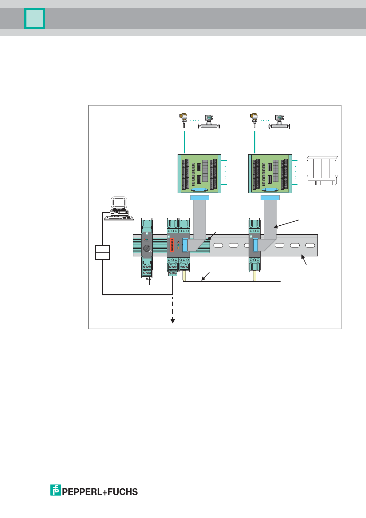
Converter
26 -pin ribbon cable
14-pin ribbon cable
DIN mounting rail
up to 31 HART multiplexer masters
up to 15 HART multiplexer slaves per master
24 V DC
RS-485
connection
Up to 16
field devices
Up to 16
field devices
DCS
Computer-based
maintenance station
1
2
3
4
5
6
7
8
19
1713 181620142115
KFD0-HMM-16
KFD0-HMS-16
1
3
4
6
2
5
13 15
12
9
10
7
14
11
8
KFD2-EB2
ERRPWR
!
5 AT
IIIS1
Termination
board
Termination
board
Power Rail
System Description
3.4.1 External Mounting
The multiplexer master and multiplexer slaves are connected to a termination board.
The termination board forwards the signals via screw terminals. The termination board
establishes the connection to the connected multiplexer masters and multiplexer slaves in
parallel or series. This type of mounting is independent of the process control system used and
of any existing control units.
2018-04
Figure 3.3
13
HART Multiplexer System KFD*-HM*-16
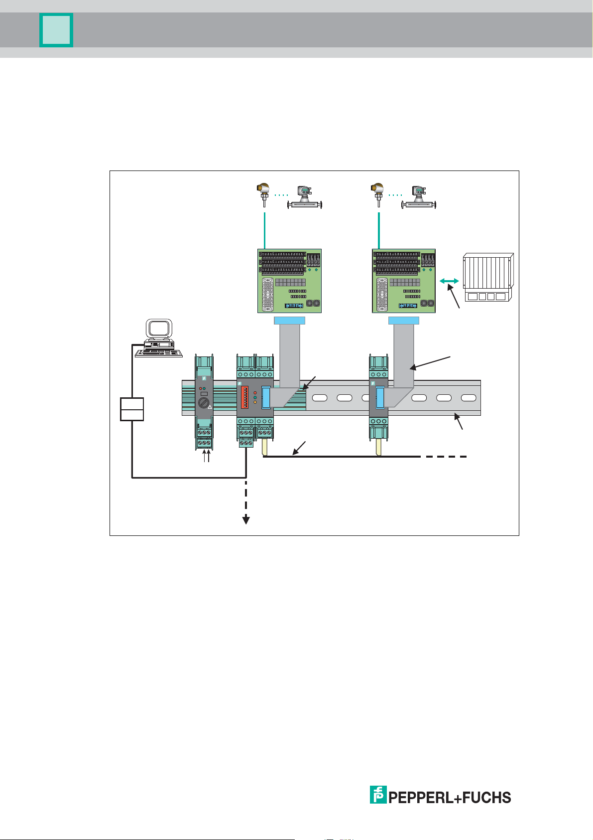
Converter
26 -pin ribbon cable
14-pin ribbon cable
DIN mounting rail
up to 15 HART multiplexer slaves per master
24 V DC
Up to 16
field devices
Up to 16
field devices
DCS
Connection via
system connector
Computer-based
maintenance station
up to 31 HART multiplexer masters
RS-485
connection
1
2
3
4
5
6
7
8
19
1713 181620142115
KFD0-HMM-16
KFD0-HMS-16
1
3
4
6
2
5
13 15
12
9
10
7
14
11
8
KFD2-EB2
ERRPWR
!
5 AT
IIIS1
Termination
board
Termination
board
Power Rail
System Description
3.4.2 Mounting Integrated in the Process Control System
The multiplexer master and multiplexer slaves are connected to a termination board.
The termination board forwards the signals to the process control system via screw terminals
and system cables. The termination board establishes the connection to the connected
multiplexer masters and multiplexer slaves in parallel or series. The termination boards are
specifically tailored to the individual process control systems.
14
Figure 3.4
2018-04
HART Multiplexer System KFD*-HM*-16
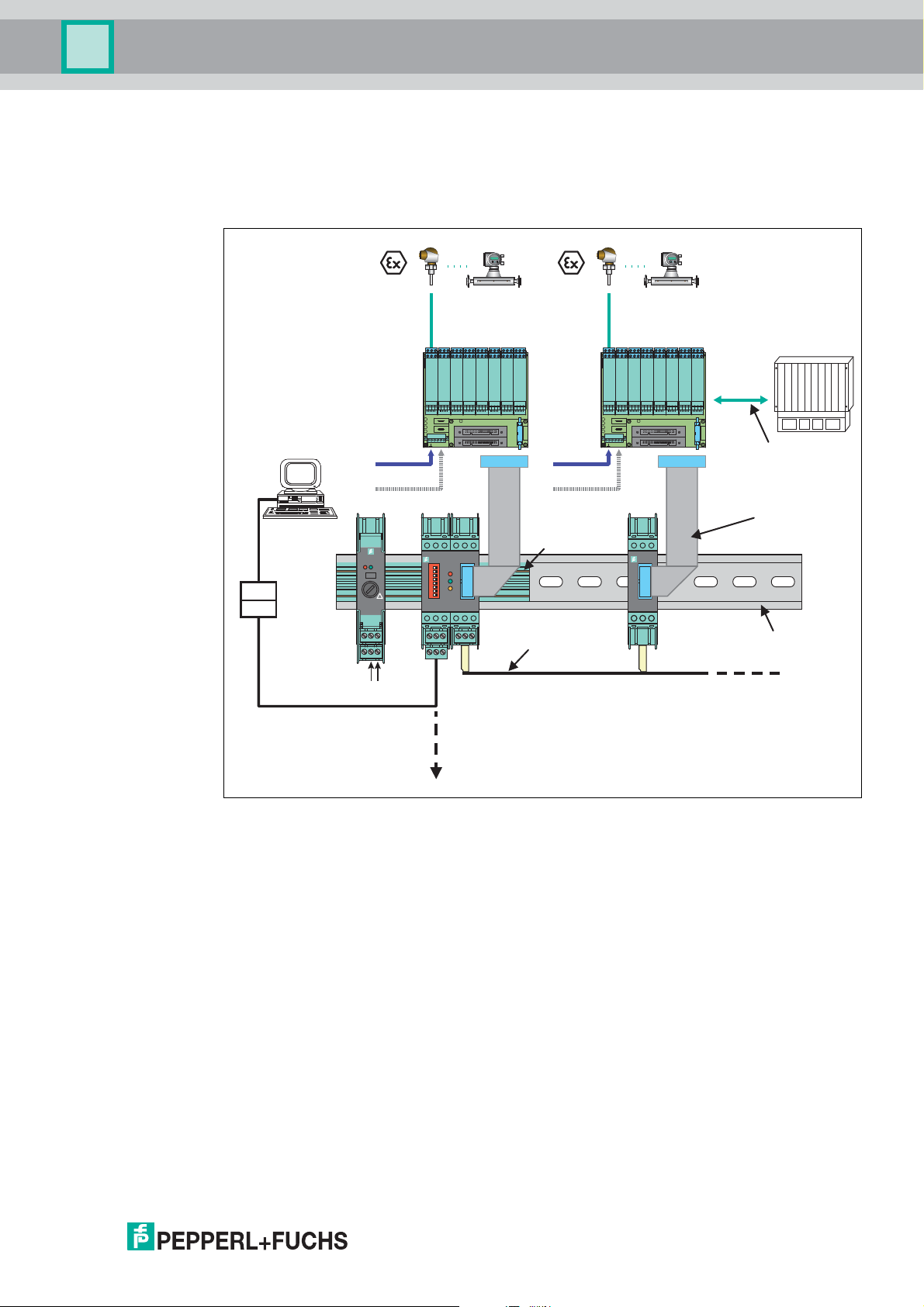
Converter
26 -pin ribbon cable
14-pin ribbon cable
DIN mounting rail
up to 15 HART multiplexer slaves per master
24 V DC
Up to 16
field devices
DCS
Redundant
power supply
Power supply
Termination board
with isolators
Up to 16
field devices
Redundant
power supply
Power supply
Termination board
with isolators
Connection via
system connector
Computer-based
maintenance station
up to 31 HART multiplexer masters
RS-485
connection
1
2
3
4
5
6
7
8
19
1713 181620142115
KFD0-HMM-16
KFD0-HMS-16
1
3
4
6
2
5
13 15
12
9
10
7
14
11
8
KFD2-EB2
ERRPWR
!
5 AT
IIIS1
Power Rail
System Description
3.4.3 Mounting Integrated into the K-System
If you use this connection option, the signals can be transferred directly from the
termination boards of the K-system to the multiplexer master and multiplexer slaves via a
system connector.
2018-04
Figure 3.5
15
HART Multiplexer System KFD*-HM*-16
Mounting and Installation
4 Mounting and Installation
Danger!
Explosion hazard from damaged electronic components
Premature wear of electronic components in a device that was previously used in a general
electrical installation can cause sparks that can ignite the surrounding potentially explosive
atmosphere.
Never install devices that have already been operated in general electrical installations in
electrical installations used in combination with hazardous areas!
Danger!
Explosion hazard from pollution
An excessively polluted surface of the device can become conductive and consequently
ignite a surrounding potentially explosive atmosphere.
Ensure that you install the device only in environments with a pollution degree 2 or better
according to IEC/EN 60664–1.
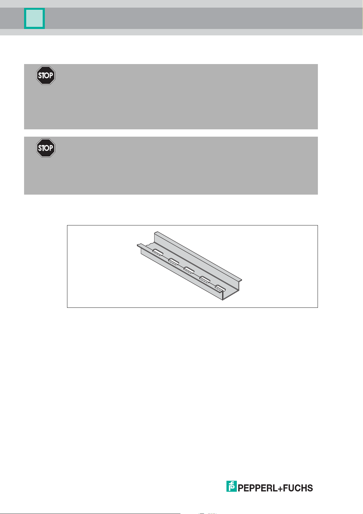
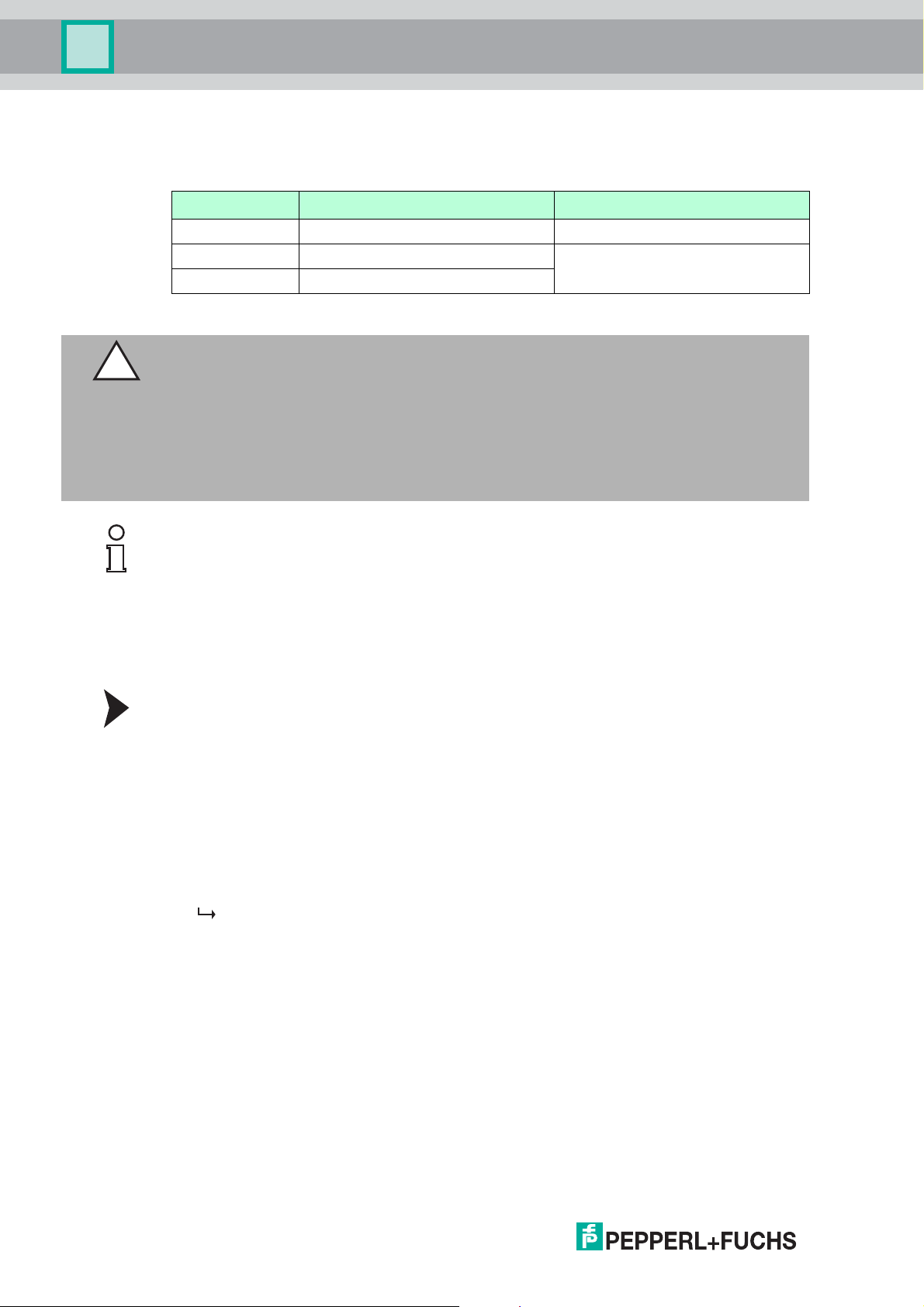
4.1 DIN Mounting Rail
The devices are mounted on a 35 mm DIN mounting rail according to EN 60715.
Figure 4.1 Example: DIN mounting rail UPR-MR (35 mm x 15 mm)
16
2018-04
HART Multiplexer System KFD*-HM*-16
1
2
34
Mounting and Installation
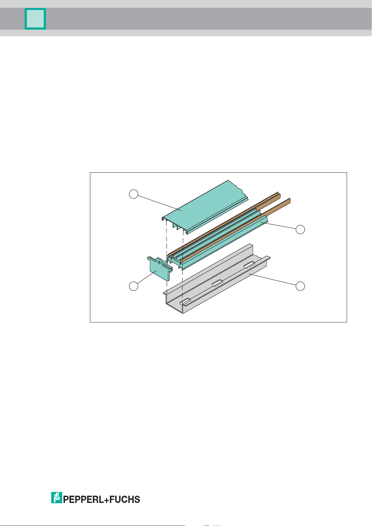
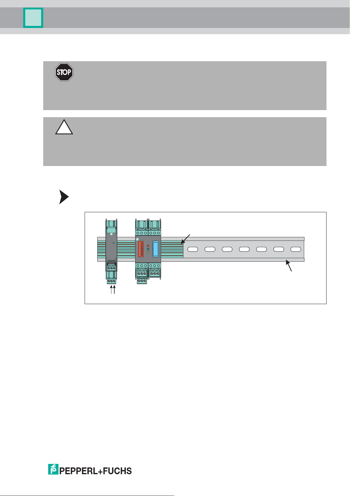
4.2 Power Rail
To reduce wiring and installation costs, Power Rail is the optimum solution. The Power Rail is a
DIN mounting rail with plastic insert, that delivers power to the devices (24 V DC) and transfers
bus signals and a collective error message.
The Power Rail is factory-equipped with cover and end caps. These parts cover empty and
open segments of the Power Rail. Thus, the Power Rail is protected from contamination.
Additionally the cover and end caps prevent that electrically conductive parts come in contact
with the Power Rail.
Power Rail UPR-03
The Power Rail UPR–03 has 3 conductors.
• 2 conductors for power
• 1 conductor for collective error messaging
Figure 4.2 Example: Power Rail UPR-03
1 Cover UPR-COVER
2 Insert UPR-INS-03
3 DIN mounting rail UPR-MR (35 mm x 15 mm)
4 End cap UPR-E
2018-04
17
HART Multiplexer System KFD*-HM*-16
Mounting and Installation
4.3 Mounting
Mounting in a Non-Hazardous Area
Mounting the Device
Snap the device onto the DIN mounting rail from above. See the next figure.
Mounting in Areas that Require Equipment Protection Level Gc
Danger!
Explosion hazard from wrong mounting
The device safety can be impaired by external environmental influences and by mechanical
stress. That can lead to sparking that can ignite a surrounding potentially explosive
atmosphere.
Mount the device in a surrounding enclosure that complies with IEC/EN 60079–0and that is
rated with the degree of protection IP54 according to IEC/EN 60529.
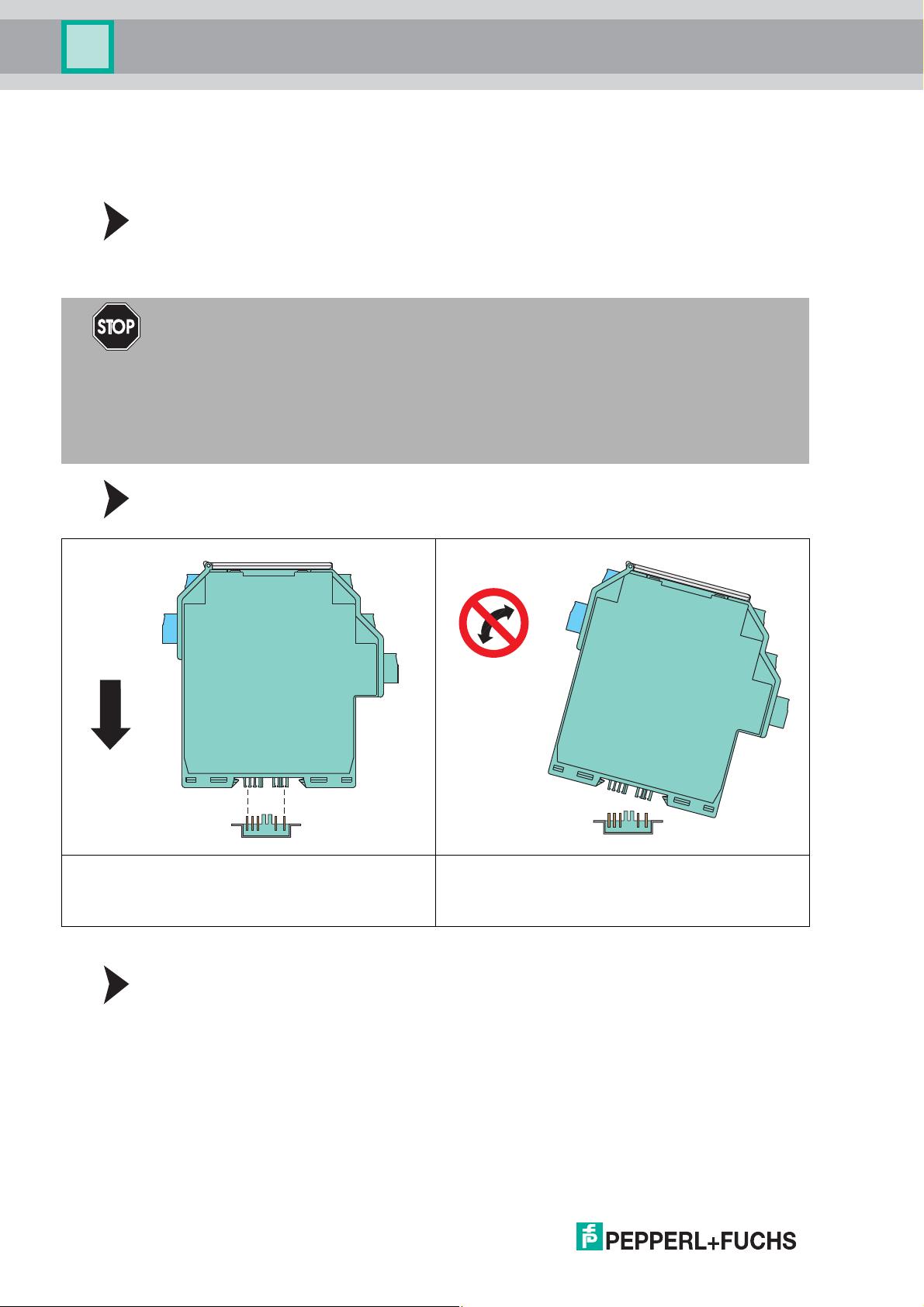
Mounting the Device
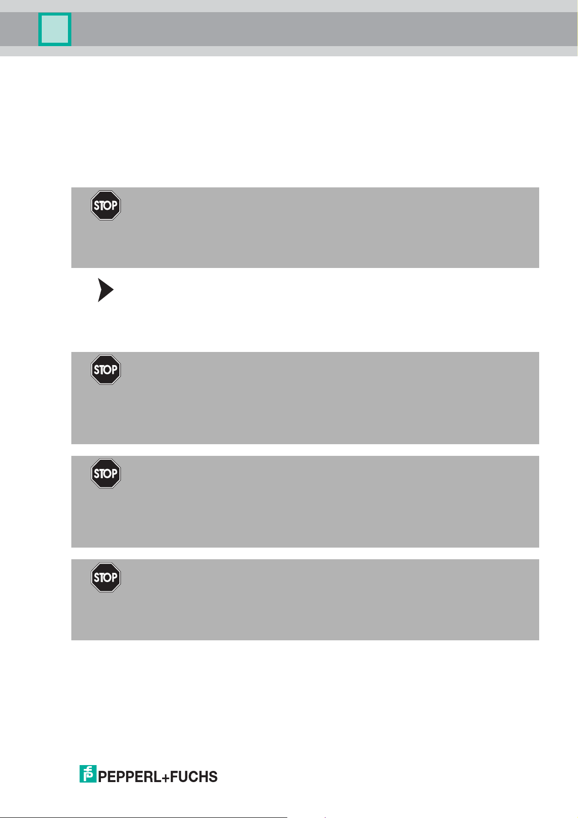
Snap the device onto the DIN mounting rail from above. See the figure below.
CORRECT:
Device snapped on vertically from above.
Figure 4.3
INCORRECT:
Device snapped on at an angle from the side.
This may result in damage to the contacts and the
failure of the device.
Mounting Terminal Blocks
Attach the terminal blocks or remove the terminal blocks.
2018-04
18
HART Multiplexer System KFD*-HM*-16
Mounting and Installation
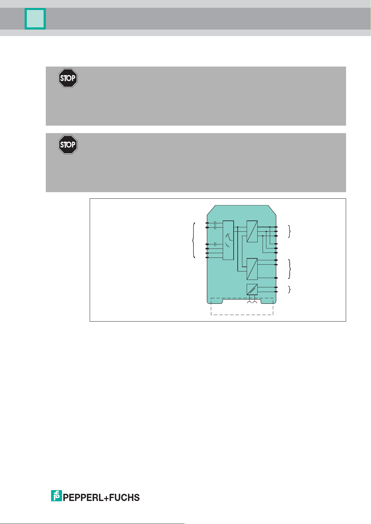
4.4 Connecting the Multiplexer Master
Danger!
Explosion hazard from using of non-intrinsically safe circuits in intrinsically safe circuits
Using non-intrinsically safe devices in intrinsically safe circuits suspends the type of
protection. This can ignite the surrounding potentially explosive atmosphere.
Do not use HART multiplexer devices and HART termination boards in intrinsically safe
circuits.
Danger!
Explosion hazard from live wiring of circuits
If you connect or disconnect energized circuits in a potentially explosive atmosphere, sparks
can ignite the surrounding atmosphere.
Only connect or disconnect energized circuits in the absence of a potentially explosive
atmosphere.
KFD2-HMM-16
Termination
Board
1
2
...
23
24
25
26
Power Rail
HART
...
24 V DC
Figure 4.4 Connection of the KFD2-HMM-16 HART multiplexer master
19
20
21
13
14
15
14
17+
18-
1
2
...
GND
TT+
RS-485
KFD0-HMS-16
24 V DC
Zone 2
2018-04
19
HART Multiplexer System KFD*-HM*-16
DIN mounting rail
1
2
3
4
5
6
7
8
19
1713 181620142115
KFD0-HMM-16
24 V DC
Mounting and Installation
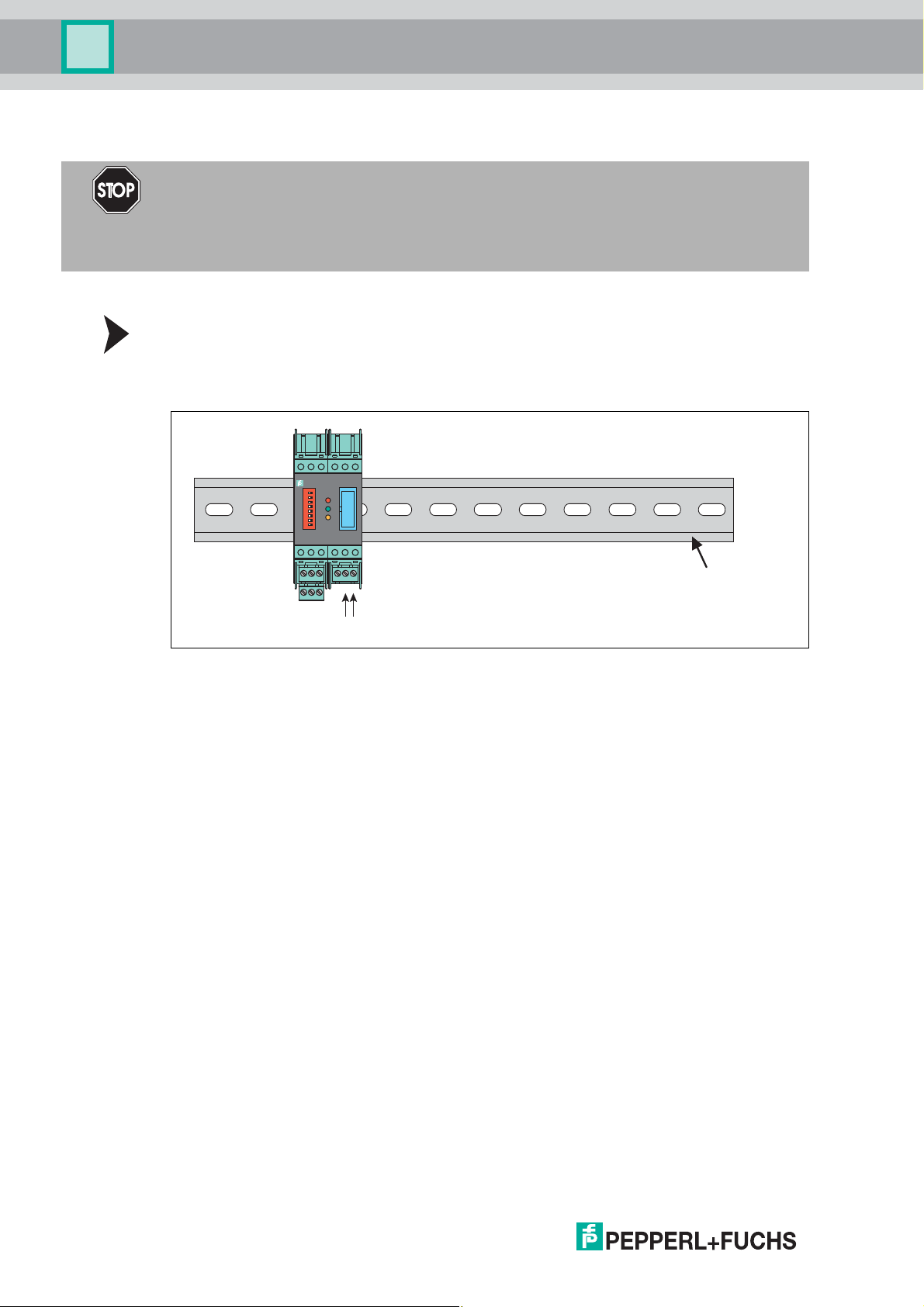
4.4.1 Supplying the Multiplexer Master with Power without Power Rail
Danger!
Danger to life from electric shock
Absent or insufficient insulation can result in electric shock.
Only connect supplies that provide protection against electric shock (e. g. SELV or PELV).
You can use the terminals to supply the multiplexer master with 24 VDC.
Connecting the Multiplexer Master Power Supply
Connect the power supply to terminals 17 and 18.
Observe the tightening torque for the terminal screws. The tightening torque is
0.5 Nm to 0.6 Nm.
Figure 4.5
20
2018-04
HART Multiplexer System KFD*-HM*-16
DIN mounting rail
24 V DC
1
2
3
4
5
6
7
8
19
1713 181620142115
KFD0-HMM-16
PWR
1
3
4
6
2
5
13 15
12
9107
14
11
8
Power Rai l
24 V DC
Mounting and Installation
4.4.2 Supplying the Multiplexer Master with Power with Power Rail
Danger!
Danger to life from electric shock
Absent or insufficient insulation can result in electric shock.
Only connect supplies that provide protection against electric shock to power feed modules
(e.g.SELVorPELV).
Caution!
Property damage from use of isolators for Power Rail supply
Using the isolators for Power Rail supply can damage the isolators and make the Power Rail
fail.
Do not supply the Power Rail via isolators.
You can use the Power Rail to supply the multiplexer master with 24 VDC. The supply is
provided using the KFA6-STR-1.24.500 power supply, for example.
Connecting the Multiplexer Master Power Supply
Connect the power supply via Power Rail.
Figure 4.6
2018-04
21
HART Multiplexer System KFD*-HM*-16
Mounting and Installation
4.4.3 Connecting the Multiplexer Master to a Computer
The multiplexer master is connected to the computer via an RS-485 interface.
Terminal Designation Meaning
13, 19 Shield Cable shielding
14, 20 RxD/TxD - (RS-485 B–) RS-485 differential signal
15, 21 RxD/TxD + (RS-485 B+)
Table 4.1 Connector assignment for removable terminals
Caution!
Risk of electric shock or property damage due to inadequate grounding
If the cable shield is not connected to the protective earth correctly, this may result in potential
equalization currents. These currents may injure operating personnel or cause property
damage.
Ground the cable shield at only one end of the line. Observe the applicable laws, standards,
and directives for the operating location.
Note!
To connect the multiplexer master and computer, you need an interface converter.
Different interface converters are required depending on the connection on your computer.
We recommend the following converters:
• Interface converter from RS-485 to RS-232: Telebyte model 285, from Telebyte
• Interface converter from RS-485 to RJ45, Com-Server++, from W&T
• Interface converter from RS-485 to USB: I-7561-CR, from ICP
Connecting the Multiplexer Master to a Computer
1. Connect a computer or a process control system to terminals 13, 14, and 15.
Observe the tightening torque for the terminal screws. The tightening torque is
0.5 Nm to 0.6 Nm.
Do not exceed a maximum cable length of 1200 m. Use a shielded, twisted, two-core cable.
2. In the case of long cable lengths and high baud rates, install a terminator at each end of the
RS-485 line. Use terminators of 120 to 220 .
If the RS-485 line ends at the multiplexer master and is not routed to other devices, use the
second RS-485 connection at terminals 20 and 21 to connect a terminator.
If you use an interface converter, install a terminator on the interface converter and an
interface converter at the other end of the line.
In the case of short cable lengths and low baud rates, no terminators are required.
Observe the RS-485 specifications.
3. Connect additional participants to terminals 19, 20, and 21.
Observe the tightening torque for the terminal screws. The tightening torque is
0.5 Nm to 0.6 Nm.
Do not exceed a cable length of 1200 m. Use a shielded, twisted, two-core cable.
22
2018-04
HART Multiplexer System KFD*-HM*-16
Mounting and Installation
4.4.4 Connecting the Multiplexer Devices to the Termination Board
The device is connected to the termination board via a 26-pin ribbon cable. The device has a
26-pin IDC socket on the front of the device for this purpose. 16 cables are intended for
the HART signal of the analog measuring circuits of the field devices. The remaining 10 cables
are connected to ground. For the assignment of the IDC socket, see chapter 9.2.
Pepperl+Fuchs provides special termination boards. Various connection options are available
for these termination boards.
Danger!
Explosion hazard from exposed conductors
Exposed conductors of inadequately attached cables can cause sparks that can ignite
the surrounding potentially explosive atmosphere.
When installing the device ensure that the cables are adequately attached.
Connecting Multiplexer Devices, Field Devices, and the Termination Board
Connect the multiplexer device to the termination board via the 26-pin ribbon cable K-HM26.
See chapter 3.4.
4.5 Connecting the Multiplexer Slaves
Danger!
Explosion hazard from using of non-intrinsically safe circuits in intrinsically safe circuits
Using non-intrinsically safe devices in intrinsically safe circuits suspends the type of
protection. This can ignite the surrounding potentially explosive atmosphere.
Do not use HART multiplexer devices and HART termination boards in intrinsically safe
circuits.
Danger!
Explosion hazard from live wiring of circuits
If you connect or disconnect energized circuits in a potentially explosive atmosphere, sparks
can ignite the surrounding atmosphere.
Only connect or disconnect energized circuits in the absence of a potentially explosive
atmosphere.
Danger!
Explosion hazard from exposed conductors
Exposed conductors of inadequately attached cables can cause sparks that can ignite
the surrounding potentially explosive atmosphere.
2018-04
When installing the device ensure that the cables are adequately attached.
23
HART Multiplexer System KFD*-HM*-16
KFD0-HMS-16
1
2
23
...
...
1
2
14
...
Termination
Board
KFD2-HMM-16/
KFD0-HMS-16
24
25
26
Zone 2
HART
14-pin ribbon cable
DIN mounting rail
1
2
3
4
5
6
7
8
19
1713 181620142115
KFD0-HMM-16
KFD0-HMS-16
Mounting and Installation
Connecting the Device
1. Connect the terminationboard via the 26-pinribboncable K-HM26.
2. Connect the multiplexer master and additional multiplexer slaves via the 14pin ribbon cable K-HM14.
Figure 4.7 Connection of the KFD0-HMS-16 HART multiplexer slave
4.5.1 Supplying the Multiplexer Slaves
The multiplexer slaves are supplied with power from the multiplexer master
via the 14-pin ribbon cable.
Connecting the Multiplexer Slave Power Supply
Connect the multiplexer slave to the multiplexer master via the 14-pin ribbon cable K-HM14.
Figure 4.8
24
2018-04
HART Multiplexer System KFD*-HM*-16
14-pin ribbon cable
DIN mounting rail
1
2
3
4
5
6
7
8
19
1713 181620142115
KFD0-HMM-16
KFD0-HMS-16
Mounting and Installation
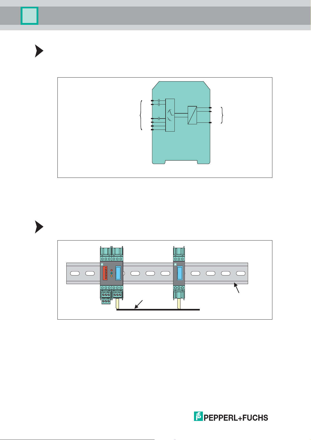
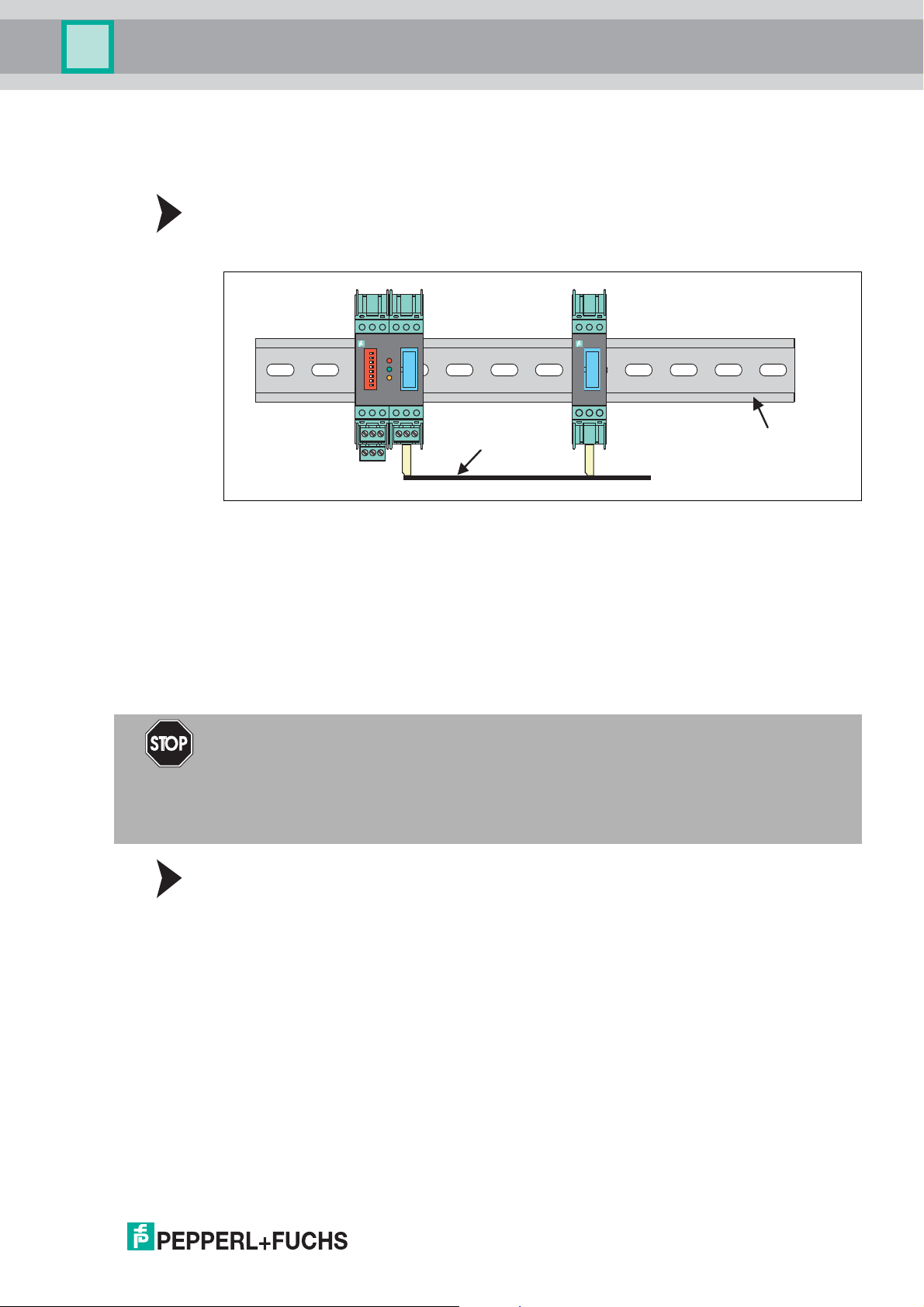
4.5.2 Connection between Multiplexer Master and Multiplexer Slaves
The multiplexer slaves are connected to the multiplexer master via the 14-pin ribbon cable.
Connecting Multiplexer Master and Multiplexer Slaves
Connect the multiplexer master and the multiplexer slaves via the 14-pin ribbon cable
K-HM14.
Figure 4.9
4.5.3 Connecting the Multiplexer Devices to the Termination Board
The device is connected to the termination board via a 26-pin ribbon cable. The device has a
26-pin IDC socket on the front of the device for this purpose. 16 cables are intended for
the HART signal of the analog measuring circuits of the field devices. The remaining 10 cables
are connected to ground. For the assignment of the IDC socket, see chapter 9.2.
Pepperl+Fuchs provides special termination boards. Various connection options are available
for these termination boards.
Danger!
Explosion hazard from exposed conductors
Exposed conductors of inadequately attached cables can cause sparks that can ignite
the surrounding potentially explosive atmosphere.
When installing the device ensure that the cables are adequately attached.
Connecting Multiplexer Devices, Field Devices, and the Termination Board
Connect the multiplexer device to the termination board via the 26-pin ribbon cable K-HM26.
See chapter 3.4.
2018-04
25

HART Multiplexer System KFD*-HM*-16
Mounting and Installation
4.6 Connecting the Termination Board
Danger!
Explosion hazard from using of non-intrinsically safe circuits in intrinsically safe circuits
Using non-intrinsically safe devices in intrinsically safe circuits suspends the type of
protection. This can ignite the surrounding potentially explosive atmosphere.
Do not use HART multiplexer devices and HART termination boards in intrinsically safe
circuits.
Danger!
Explosion hazard from live wiring of circuits
If you connect or disconnect energized circuits in a potentially explosive atmosphere, sparks
can ignite the surrounding atmosphere.
Only connect or disconnect energized circuits in the absence of a potentially explosive
atmosphere.
Danger!
Danger to life from electric shock
Absent or insufficient insulation can result in electric shock.
Only connect supplies that provide protection against electric shock to power feed modules
(e.g.SELVorPELV).
Danger!
Danger to life from electric shock
Absent or insufficient insulation can result in electric shock.
• Maintain sufficient distance between the connection lines, terminals, housing, and
the environment.
• Insulate connection lines, terminals, and the housing from the environment.
Danger!
Danger to life from incorrect installation
Incorrect installation of cables and connection lines can compromise the function and
the electrical safety of the device.
• Observe the permissible core cross section of the conductor.
• When using stranded conductors, crimp wire end ferrules on the conductor ends.
• Use only one conductor per terminal.
• When installing the conductors the insulation must reach up to the terminal.
• Observe the tightening torque of the terminal screws.
26
2018-04
HART Multiplexer System KFD*-HM*-16
Mounting and Installation
4.6.1 Connecting Field Devices to the Termination Board
Pepperl+Fuchs provides special termination boards. Various connection options are available
for these termination boards. See the manual "K-System – Isolators and Termination Boards."
Connecting the Termination Board and Field Devices
1. Connect the HART-compatible field devices to the termination board using screw terminals
or spring terminals. See chapter 3.4.1 and 3.4.2.
Observe the tightening torque for the terminal screws. The tightening torque is
0.5 Nm to 0.6 Nm.
or
2. Control units are mounted on the termination board. Connect the field devices to the
control unit using screw terminals or spring terminals. See chapter 3.4.3.
Observe the tightening torque for the terminal screws. The tightening torque is
0.5 Nm to 0.6 Nm.
4.6.2 Connecting the Process Control System to the Termination Board
Pepperl+Fuchs provides special termination boards. Various connection options are available
for these termination boards.
Connecting the Termination Board and Process Control System
1. Connect the process control system to the termination board using screw terminals
or spring terminals. See chapter 3.4.1.
Observe the tightening torque for the terminal screws. The tightening torque is
0.5 Nm to 0.6 Nm.
or
2. Connect the process control system to the termination board via a manufacturer-specific
system connector. See chapter 3.4.2 and 3.4.3.
4.7 Information Regarding Electromagnetic Compatibility
The device is intended for use in electrically conductive and grounded switch cabinets.
Shielding Cables
1. Shield cables that are leaded into the switch cabinet.
2. Connect the switch cabinet and shield directly in the cable gland.
3. Lead unshielded cables (e. g. supply lines) into the switch cabinet via filter.
2018-04
27

HART Multiplexer System KFD*-HM*-16
Commissioning
5 Commissioning
Checklist for Commissioning
The commissioning of the multiplexer master is summarized in the following checklist.
The steps required for commissioning the multiplexer master refer to the chapters where
the respective procedure is described.
1. Installation of field devices
2. Selection and connection of the termination boards, see chapter 3.4
3. Selection and connection of the control units
4. Connection of the process control system
5. Connection of the multiplexer master, see chapter 4.4
6. Connection of the maintenance station.
If necessary, use interface converters, see chapter 4.4.3.
Observe the polarity of the RS-485 connection, see chapter 4.4.3.
Specify the RS-485 address and the baud rate.
7. Wait for the switch-on process, see chapter 5.2.4.
8. Perform parameterization, see chapter 5.2.5.
9. Specify the multiplexer devices used in the module table, see chapter 7.1.2.
10. Build signal loops, see chapter 7.1.5.
11. If desired, activate the scan function, see chapter 7.1.6.
5.1 Data Access to the Connected Field Devices
The operating tool used determines how data on the connected field devices is accessed.
The field devices are generally found in a project tree beneath the multiplexer slaves.
The multiplexer master integrates the slave unit with slave address 0. Device data,
device parameters, and device diagnoses can be accessed via the project tree.
For the structure of a project tree, see chapter 6.8.
The data, parameter, and diagnostic windows display the data of the underlying
HART commands that differ according to the field device. Only universal commands and
common practice commands have the same function for all devices. The information about the
devices themselves, the process values, and some diagnostic information can thus be
represented in a uniform manner.
5.2 Configuration of the Multiplexer Master
5.2.1 Connection to the Maintenance Station or to the
Process Control System
28
The connection to the maintenance station or to the process control system is via a multidropenabled RS-485 interface, see chapter 4.4.3. The baud rate for this interface can be set via the
DIP switch. The device address for communication via RS-485 is also set via the DIP switch.
When setting the address, make sure that no address is assigned more than once, as
otherwise this may lead to communication faults and even communication failure. The
baud rate set must match that of the maintenance station.
2018-04
 Loading...