

Page 1
Current/Voltage Converter
Zone 2
Div. 2
Zone 0, 1, 2
Div. 1, 2
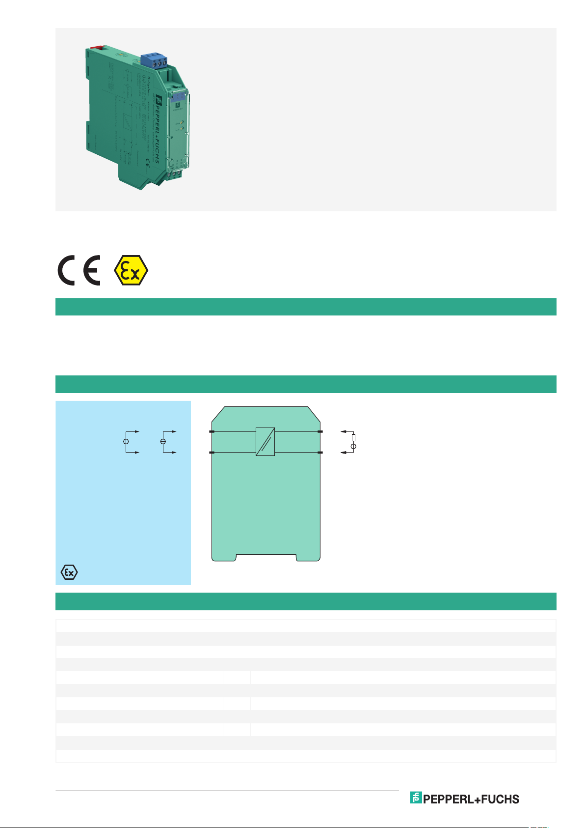
KFD0-CC-Ex1
2-
1+
8-
9+
V
mA
V
Germany: +49 621 776 2222Pepperl+Fuchs Group
Refer to "General Notes Relating to Pepperl+Fuchs Product Information".
USA: +1 330 486 0002 Singapore: +65 6779 9091
www.pepperl-fuchs.com pa-info@us.pepperl-fuchs.com pa-info@sg.pepperl-fuchs.com
pa-info@de.pepperl-fuchs.com
KFD0-CC-Ex1
1-channel isolated barrier
<
24 V DC supply (loop powered)
<
Current or voltage input
<
Output: 4 ... 20 mA
<
Potentiometer or DIP switch selectable ranges
<
Line fault detection (LFD)
<
Function
This isolated barrier is used for intrinsic safety applications. It converts a 2-wire voltage or current in the hazardous area to a 4 mA ... 20 mA signal
in the safe area.
The device can be used to double signals in 20 mA measurement circuits due to the limited current signal input load of 50 Ω.
DIP switches and potentiometers make field calibration easy.
Since this isolator is loop-powered, use the technical data to verify that the proper voltage is available to the field devices.
Connection
Technical Data
General specifications
Signal type Analog input
Supply
Rated voltage U
Power dissipation 0.4 W
Input
Connection side field side
Connection terminals 1+, 2Current range 0 ... 20 mA , load ≤ 50 Ω
Voltage range 0 ... 10 V , load ≥ 100 kΩ
Output
Release date: 2020-09-23 Date of issue: 2020-09-23 Filename: 043690_eng.pdf
12 ... 35 V DC loop powered
r
1
Page 2
Current/Voltage Converter KFD0-CC-Ex1
Germany: +49 621 776 2222Pepperl+Fuchs Group
Refer to "General Notes Relating to Pepperl+Fuchs Product Information".
USA: +1 330 486 0002 Singapore: +65 6779 9091
www.pepperl-fuchs.com pa-info@us.pepperl-fuchs.com pa-info@sg.pepperl-fuchs.com
pa-info@de.pepperl-fuchs.com
Technical Data
Connection side control side
Connection terminals 9+, 8Load (U -12 V) / 0.02 A
Current output 4 ... 20 mA , limited to ≤ 35 mA
Fault signal downscaling ≤ 3 mA
Transfer characteristics
Deviation
After calibration 0.1 % of full-scale value
Temperature effect span: 0.050 % of span /K ; zero point: 0.060 % of span /K
Linearization ≤ 0.04 % of full-scale value
Influence of supply voltage 6.5 ppm/V
Rise time 250 ms
Galvanic isolation
Input/Output safe isolation according to EN 50178, rated insulation voltage 253 V
Indicators/settings
Control elements DIP-switch
potentiometer
Configuration via DIP switches
via potentiometer
Labeling space for labeling at the front
Directive conformity
Electromagnetic compatibility
Directive 2014/30/EU EN 61326-1:2013 (industrial locations)
Conformity
Galvanic isolation EN 50178:1997
Degree of protection IEC 60529:2001
Ambient conditions
Ambient temperature -20 ... 60 °C (-4 ... 140 °F)
Mechanical specifications
Degree of protection IP20
Connection screw terminals
Mass approx. 100 g
Dimensions 20 x 119 x 115 mm (0.8 x 4.7 x 4.5 inch) , housing type B2
Mounting on 35 mm DIN mounting rail acc. to EN 60715:2001
Data for application in connection with hazardous areas
EU-Type Examination Certificate ZELM 00 ATEX 0034
Marking 1 II (1)GD [EEx ia] IIC
Input EEx ia IIC
Voltage U
Current I
Power P
9.6 V
o
0.5 mA
o
1.1 mW linear characteristic
o
Output
Maximum safe voltage U
60 V (Attention! The rated voltage can be lower.)
m
Certificate TÜV 01 ATEX 1777 X
Marking 1 II 3G Ex nA II T4
Galvanic isolation
Input/Output safe electrical isolation acc. to IEC/EN 60079-11, voltage peak value 375 V
Directive conformity
Directive 2014/34/EU EN 60079-0:2012+A11:2013 , EN 60079-11:2012 , EN 60079-15:2010
International approvals
CSA approval
Control drawing 116-0132
General information
Release date: 2020-09-23 Date of issue: 2020-09-23 Filename: 043690_eng.pdf
eff
2
Page 3

SPAN
ZERO
1
3
4
6
2
5
13 15
12
9
10
7
14
11
8
KFD0-CC-Ex1
Span fine adjustment
Zero point
fine adjustment
DIP-switch
range, zero point
coarse adjustment
Removable terminal
blue
Removable terminal
green
Front view
Current/Voltage Converter KFD0-CC-Ex1
Germany: +49 621 776 2222Pepperl+Fuchs Group
Refer to "General Notes Relating to Pepperl+Fuchs Product Information".
USA: +1 330 486 0002 Singapore: +65 6779 9091
www.pepperl-fuchs.com pa-info@us.pepperl-fuchs.com pa-info@sg.pepperl-fuchs.com
pa-info@de.pepperl-fuchs.com
Technical Data
Supplementary information Observe the certificates, declarations of conformity, instruction manuals, and manuals
where applicable. For information see www.pepperl-fuchs.com.
Assembly
Release date: 2020-09-23 Date of issue: 2020-09-23 Filename: 043690_eng.pdf
3
Page 4

Germany: +49 621 776 2222Pepperl+Fuchs Group
Refer to "General Notes Relating to Pepperl+Fuchs Product Information".
USA: +1 330 486 0002 Singapore: +65 6779 9091
www.pepperl-fuchs.com pa-info@us.pepperl-fuchs.com pa-info@sg.pepperl-fuchs.com
pa-info@de.pepperl-fuchs.com
Current/Voltage Converter
Transmitter
power supply
Example
Transmitter
Output 1
Output 2
4 mA ... 20 mA
4 mA ... 20 mA
KFD0-CC-1
Current
meas. range
Voltage
meas. range
Zero
point
No
functions
0
0
1234 1234
S1
S2
1
1
Measurement range Switch S1 (range) Switch S2 (zero point)
S1.1 S1.2 S1.3 S1.4 S2.1 S2.2 S2.3 S2.4
0 mA ... 20 mA
4 mA ... 20 mA
0 V ... 5 V
1 V ... 5 V
0 V ... 10 V
2 V ... 10 V
1
1
-
-
-
-
1
1
-
-
-
-
-
1
1
-
-
-
-
-
1
1
-
1
-
1
-
1
-
1
-
1
-
1
-
-
-
-
-
-
-
-
-
-
-
-
Configuration
The device is delivered with the input signal set of 4 mA ... 20 mA.
DIP switches function
KFD0-CC-Ex1
Adjustment instruction (example):
Input signal 0 mA ... 20 mA
Output signal 4 mA ... 20 mA
1. Set DIP switches S1.1 and S1.2 to the position 1. Set all other DIP switches to the position 0.
2. Set input to minimum value of 0 mA.
3. Adjust output, minimum zero point (4 mA).
4. Add maximum value of 20 mA.
5. Adjust output, range maximum value (20 mA)
Repeat steps 2. ... 5., until stable.
Release date: 2020-09-23 Date of issue: 2020-09-23 Filename: 043690_eng.pdf
4
 Loading...