

Switch Amplifier
KFA6-SR-2.3L.FA
Features
• 2-channel
• 115/230 V AC supply
• 3-wire PNP/NPN sensor or push-pull input
• Relay contact output
• DIP switch selectable functions
• Minimum/maximum control
• Up to SIL 2 acc. to IEC 61508
Function
This signal conditioner provides the galvanic isolation
between field circuits and control circuits.
The device transfers the status of 2-wire and 3-wire sensors to
the relay contact output.
The device has 2 inputs and 2 relay contact outputs.
The device can be used either as dual channel signal
conditioner or as a two-point level controller.
The device is easily configured by the use of DIP switches.
A fault is signalized by LEDs.
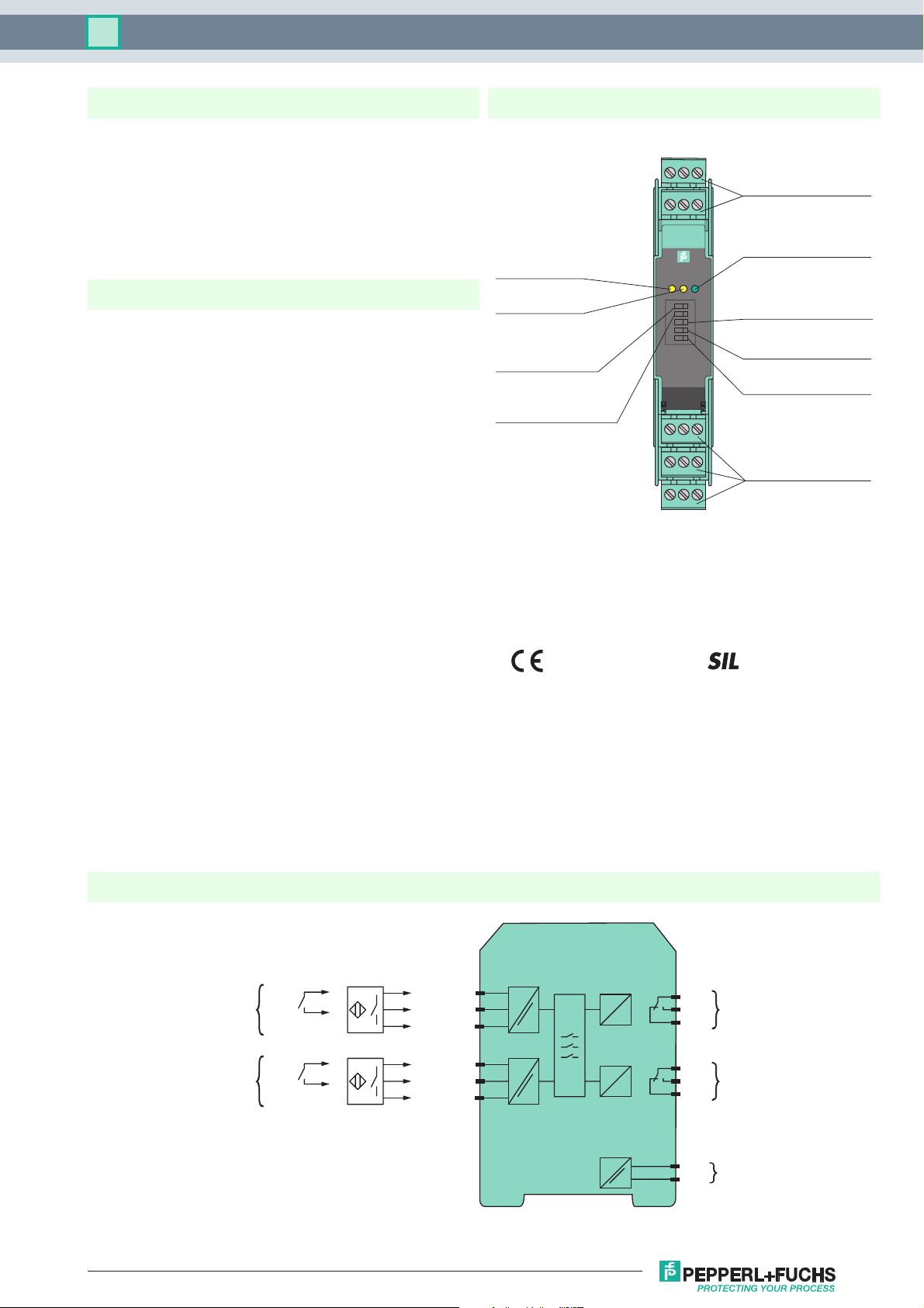
Assembly
Front view
LED yellow:
Relay output I
LED yellow:
Relay output II
Switch S1:
(mode of operation
input I)
Switch S2:
(mode of operation
input II)
1
4
KFA6-SR-2.3L
OUT1 OUT2 PWR
S1
S2
S3
S4
S5
13 15
Removable terminals
green
3
2
5
6
LED green:
Power supply
Switch S3:
(dual channel or min/max)
III
Switch S4:
(sensor type input I)
Switch S5:
9107
8
12
11
14
(sensor type input II)
Removable terminals
green
Connection
2
KFA6-SR-2.3L
1+
I
2
3-
4+
II
5
6-
10
11
12
7
I
8
9
II
Release date 2018-05-14 15:04 Date of issue 2018-05-14 182509_eng.xml
Refer to "General Notes Relating to Pepperl+Fuchs Product Information".
USA: +1 330 486 0002 Germany: +49 621 776 2222
pa-info@us.pepperl-fuchs.com pa-info@de.pepperl-fuchs.com pa-info@sg.pepperl-fuchs.com
14+
15-
230 V AC
1

Technical data KFA6-SR-2.3L.FA
General specifications
Signal type Digital Input
Functional safety related parameters
Safety Integrity Level (SIL) SIL 2
Supply
Connection terminals 14, 15
Rated voltage U
Rated current I
r
Power dissipation 2.5 W
Power consumption ≤ 7 W
Input
Connection side field side
Connection Input I: terminals 1+, 2, 3-; Input II: terminals 4+, 5, 6-
Rated values 22 ... 24 V DC / 100 mA, see notes
NPN sensor
Switching point 4 ... 13 V
PNP sensor
Switching point 4 ... 13 V
Short-circuit current 110 mA
Switching point 0-signal: < 5 V
Output
Connection side control side
Connection output I: terminals 7, 8, 9
Output I, II
Contact loading 250 V AC / 4 A / cos φ > 0.7; 40 V DC / 2 A resistive load
Energized/De-energized delay max. 6 ms
Mechanical life 107 switching cycles
Transfer characteristics
Switching frequency ≤ 10 Hz
Galvanic isolation
Input/Output safe galvanic isolation per EN 50178, voltage peak value 253 V
Input/power supply safe galvanic isolation per EN 50178, voltage peak value 253 V
Output/power supply safe galvanic isolation per EN 50178, voltage peak value 253 V
Output/Output basic insulation acc. to EN 50178, rated insulation voltage 253 V
Indicators/settings
Display elements LEDs
Labeling space for labeling at the front
Directive conformity
Electromagnetic compatibility
Directive 2004/108/EC EN 61326-1:2006
Low voltage
Directive 2006/95/EC EN 50178:1997
Conformity
Galvanic isolation EN 50178
Electromagnetic compatibility NE 21
Degree of protection IEC 60529
Ambient conditions
Ambient temperature -20 ... 60 °C (-4 ... 140 °F)
Mechanical specifications
Degree of protection IP20
Connection screw terminals
Mass approx. 150 g
Dimensions 20 x 119 x 115 mm (0.8 x 4.7 x 4.5 inch)
General information
Supplementary information Observe the certificates, declarations of conformity, instruction manuals, and manuals where applicable. For
90 ... 253 V AC , 45 ... 65 Hz
r
≤ 150 mA
1-signal: > 13 V
output II: terminals 10, 11, 12
information see
eff
Release date 2018-05-14 15:04 Date of issue 2018-05-14 182509_eng.xml
Refer to "General Notes Relating to Pepperl+Fuchs Product Information".
USA: +1 330 486 0002 Germany: +49 621 776 2222
pa-info@us.pepperl-fuchs.com pa-info@de.pepperl-fuchs.com pa-info@sg.pepperl-fuchs.com
2
Technical data KFA6-SR-2.3L.FA
Notes
Function
The device has two inputs and two relay outputs (change-over contact) and is usable either as dual channel isolated amplifier or
as two-point control (min/max control).
The inputs are designed in a way, that the signals of sensors which have PNP or NPN output transistors as well as push-pull
outputs, can be processed. In the case of sensors with push-pull outputs the switches S4 or S5 have to be set to position I. For
sensors with PNP or NPN output transistors, the switches S4 or S5 have to be set to position II. The operating behaviour of the
sensor can be selected: NO S1/S2 in position I; NC S1/S2 in position II.
Dual channel switching amplifier for binary sensors or contacts
With this function (S3 in position I) contact or sensor signals from the input are transmitted to the relay output.
Parallel operation (1 input, 2 outputs)
A signal duplication can be realized by the following measures:
• Jumper terminal 2 to terminal 5.
• One sensor to input I or II.
Two-point control (min/max control) with storage of status
On this setting (S3 in position II) the information from the two inputs is combined.
When the supply voltage is switched on, relay 1 is energised until input 2 is activated (reset input). Input 1 works as an set input.
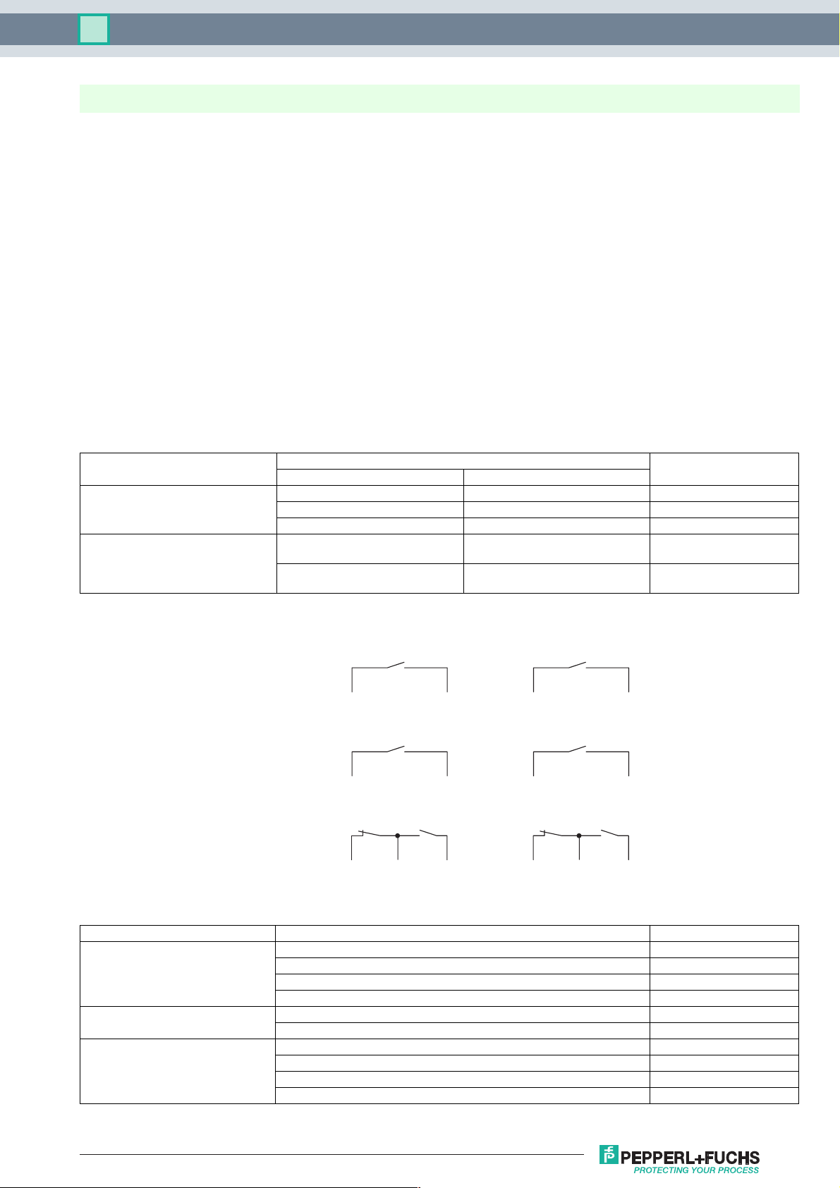
Truth table (min/max control)
Conditions Inputs Outputs
E I E II
Activation of the supply voltage not activated not activated relay energised
activated not activated relay energised
activated activated relay de-energised
Normal operation activated transition:
transition:
activated/not activated
not activated/activated
not activated relay energising
relay I and II
relay de-energising
Sensor connection
NPN output stage/contact
S4 = II
PNP output stage/contact
S4 = II S5 = II
Push-pull output stage
S4 = I S5 = I
2 3-
1+
1+
2
S5 = II
2
3-
5 6-
4+
4+
5
5
6-
Function of the DIP switches
Function Switch function Switch/position
Operating behaviour of the sensor input input 1 is activated if sensor 1 is closed S1/I
input 1 is activated if sensor 1 is open S1/II
input 2 is activated if sensor 2 is closed S2/I
input 2 is activated if sensor 2 is open S2/II
Dual channel or min/max dual channel independent S3/I
min/max function with storage of the status S3/II
Sensor type input 1: push-pull output stage, NO S4/I
input 1: PNP/NPN, NO S4/II
input 2: push-pull output stage, NO S5/I
input 2: PNP/NPN, NO S5/II
Release date 2018-05-14 15:04 Date of issue 2018-05-14 182509_eng.xml
Refer to "General Notes Relating to Pepperl+Fuchs Product Information".
USA: +1 330 486 0002 Germany: +49 621 776 2222
pa-info@us.pepperl-fuchs.com pa-info@de.pepperl-fuchs.com pa-info@sg.pepperl-fuchs.com
3

Technical data KFA6-SR-2.3L.FA
Example 1: filling of a vessel (two-point level control, S3 in position II)
Min contact or min sensor is connected to input 1 (set), max contact or max sensor is connected to input 2 (reset). Dip switch S1
and S2 are on position I. A filling pump is connected to output 1 or 2 (terminals 7/8 or 10/11).
All data refer to NO sensors.
Pump
Max
Input II
Min
Input I
with vibration limit switch
S1
S2
S3
S4
S5
I II
When the supply voltage of the KFA6-SR-2.3L is switched on, the pump will also switched on as long as the Max contact is not
activated. During operation the pump is switched off as soon as the level has reached max position. If the level reach min position,
the pump is switched on. If the KFA6-SR-2.3L has no power supply, the pump is switched off.
Example 2: emptying of a vessel (two-point level control, S3 in position II)
Max contact or max sensor is connected to input 1 (set), min contact or min sensor is connected to input 2 (reset). Dip switch S1
and S2 are set to position I. An emptying pump is connected to output 1 or 2 (terminals 7/9 or 10/12).
All data refer to NO sensors.
Max
Min
Input I
Input II
S1
S2
S3
S4
S5
I II
Pump
with vibration limit switch
When the supply voltage of the KFA6-SR-2.3L is switched on, the pump will also switched on, if max contact is activated. During
operation the pump is switched off as soon as the level has reached min position. If the level reach max position, the pump
switched on. If the KFA6-SR-2.3L has no power supply, the pump is switched on.
Comments:
1. NO with push-pull output stage means that the closing contact or transistor is connected to terminal 2 and 3 (5 and 6).
NC with push-pull output stage means that the opening contact or transistor is connected to terminal 2 and 3 (5 and 6).
2. In dip switch position S3/I (dual channel, independent) an output relay is activated if the corresponding input is activated.
Release date 2018-05-14 15:04 Date of issue 2018-05-14 182509_eng.xml
Refer to "General Notes Relating to Pepperl+Fuchs Product Information".
USA: +1 330 486 0002 Germany: +49 621 776 2222
pa-info@us.pepperl-fuchs.com pa-info@de.pepperl-fuchs.com pa-info@sg.pepperl-fuchs.com
4

Technical data KFA6-SR-2.3L.FA
Derating of the sensor currents in dependence of the ambient temperature
The maximum value of the sensor currents is controlled by a thermal overload protection of the device.
The device determines its ambient temperature and limits the sensor currents accordingly (see
figure). An inadmissibly high ambient temperature can limit the function of the sensors.
Attention
200
180
160
140
120
100
Total current in mA
80
60
40
20
Maximum value for
operation with 2 sensors
Maximum value for
operation with 1 sensor
10 20 30 40 50 60
Attention!
The maximum current per
sensor amounts to 100 mA .
Ambient temperature in °C
Release date 2018-05-14 15:04 Date of issue 2018-05-14 182509_eng.xml
Refer to "General Notes Relating to Pepperl+Fuchs Product Information".
USA: +1 330 486 0002 Germany: +49 621 776 2222
pa-info@us.pepperl-fuchs.com pa-info@de.pepperl-fuchs.com pa-info@sg.pepperl-fuchs.com
5
 Loading...