

Conductivity Switch Amplifier
KFA5-ER-1.5
Features
• 1-channel signal conditioner
• 115 V AC supply
• Level sensing input
• Adjustable range 1 kΩ ... 30 kΩ
• Relay contact output
• Minimum/maximum control
Function
This signal conditioner provides the AC measuring voltage for
the level-sensing electrodes.
Once the measured medium reaches the electrodes, the unit
reacts by energizing a form C changeover relay contact.
The module is voltage and temperature stabilized and
guarantees defined switching characteristics. An electronic
holding circuit is used that allows minimum/maximum control.
Since the conductance of the media may vary, the relay
response sensitivity is adjustable.
The normal output state can be reversed through the mode of
operation switch S1.
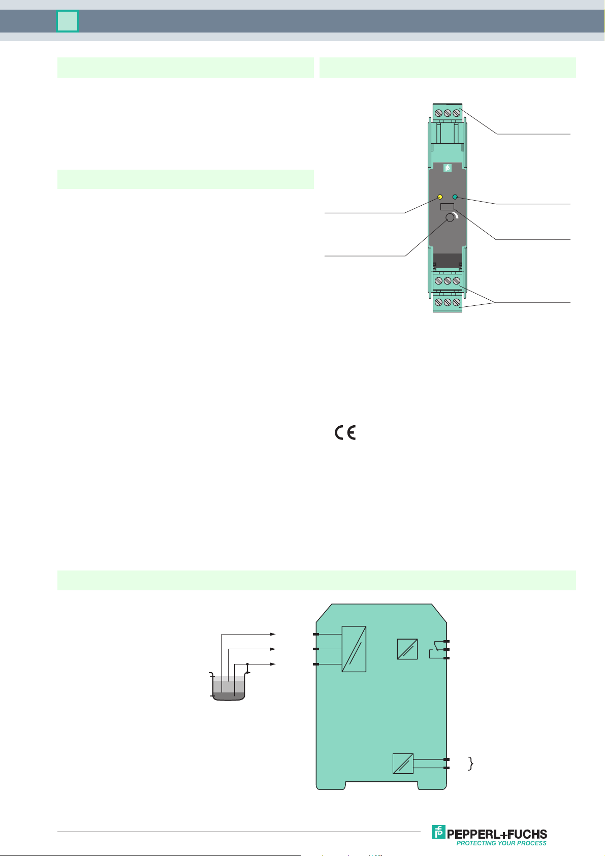
Assembly
Front view
LED yellow:
Relay output
Potentiometer
Response sensitivity
3
1
2
5
6
4
KFA5-ER-1.5
OUT PWR
S1 III
SENSITIVITY
9107118
12
Removable terminal
green
LED green:
Power supply
Switch S1
Mode of operation
Removable terminals
green
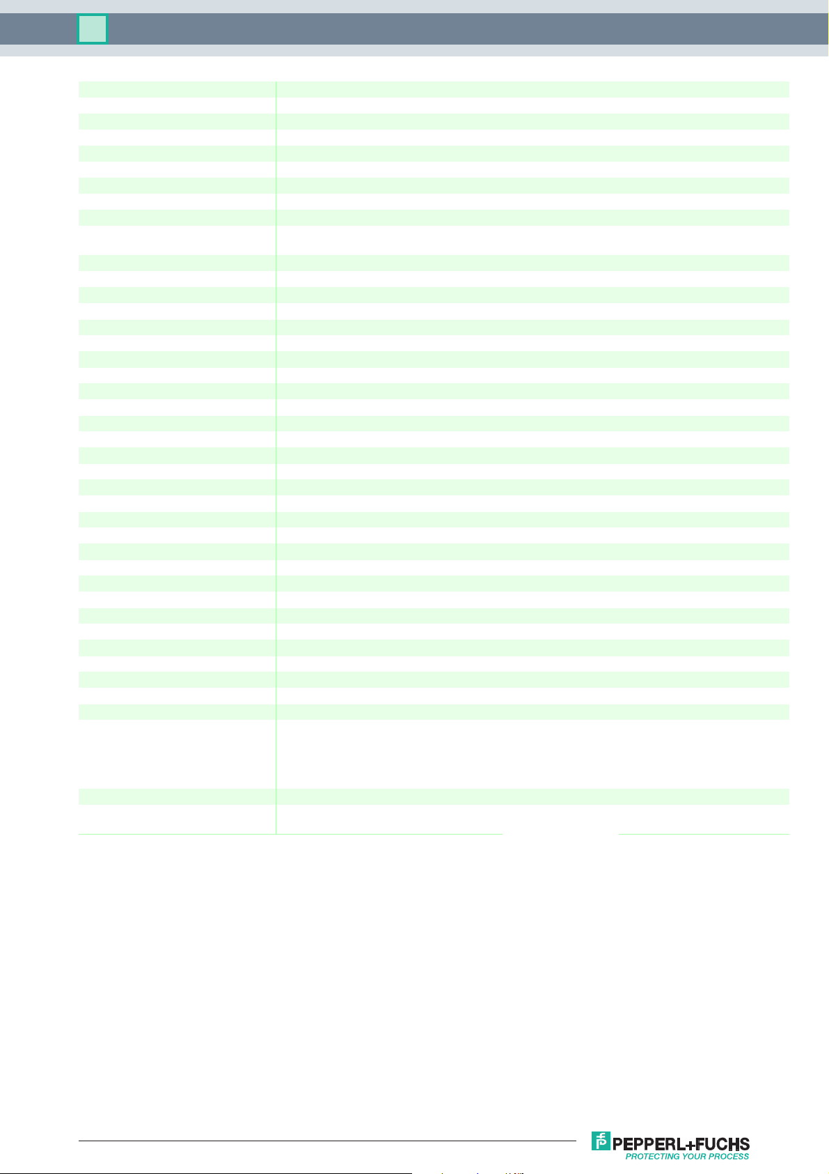
Connection
100 %
0 %
Release date 2012-09-26 14:51 Date of issue 2015-02-16 096047_eng.xml
Refer to "General Notes Relating to Pepperl+Fuchs Product Information".
Pepperl+Fuchs Group
KFA5-ER-1.5
2
3
1
7
8
9
11
12
115 V AC
1
Technical data KFA5-ER-1.5
General specifications
Signal type Digital Input
Supply
Connection terminals 11 (L1), 12 (N)
Rated voltage U
Power consumption approx. 0.8 W
Input
Connection terminals 1 (mass), 2 (min), 3 (max)
Open circuit voltage/short-circuit current approx. 10 V AC (approx. 1 Hz) / approx. 5 mA
Control input min./max. control system: terminals 1, 2, 3
Response sensitivity 1 ... 30 kΩ , adjustable via potentiometer (20 turns)
Output
Connection terminals 7, 8, 9
Output 1 changeover contact
Contact loading 253 V AC/2 A/cos φ > 0.7; 40 V DC/2 A resistive load
Energized/De-energized delay approx. 1 s / approx. 1 s
Electrical isolation
Input/Output basic insulation according to EN 50178, rated insulation voltage 253 V
Input/power supply basic insulation according to EN 50178, rated insulation voltage 253 V
Output/power supply basic insulation according to EN 50178, rated insulation voltage 253 V
Directive conformity
Electromagnetic compatibility
Directive 2004/108/EC EN 61326-1:2006
Low voltage
Directive 2006/95/EC EN 50178:1997
Conformity
Insulation coordination EN 50178:1997
Electrical isolation EN 50178:1997
Electromagnetic compatibility NE 21:2006
Degree of protection IEC 60529:2001
Ambient conditions
Ambient temperature -20 ... 60 °C (-4 ... 140 °F)
Mechanical specifications
Degree of protection IP20
Connection screw connection, max. 2.5 mm
Mass approx. 110 g
Dimensions 20 x 107 x 115 mm (0.8 x 4.2 x 4.5 in) , housing type B1
Mounting on 35 mm DIN mounting rail acc. to EN 60715:2001
Indication and operation
Control elements switch S1
General information
Supplementary information Statement of Conformity, Declaration of Conformity, Attestation of Conformity and instructions have to be
103.5 ... 126 V AC , 45 ... 65 Hz
n
on/off control system: terminals 1, 3
eff
eff
eff
2
Position I open circuit current: In the open circuit current principle, the relay becomes active when the limit is
reached.
Position II closed circuit current: In closed circuit current principle, the relay is activated when power is applied.
The relay is deactivated when the limit is reached.
observed where applicable. For information see
Release date 2012-09-26 14:51 Date of issue 2015-02-16 096047_eng.xml
Refer to "General Notes Relating to Pepperl+Fuchs Product Information".
Pepperl+Fuchs Group
2
 Loading...