

Page 1
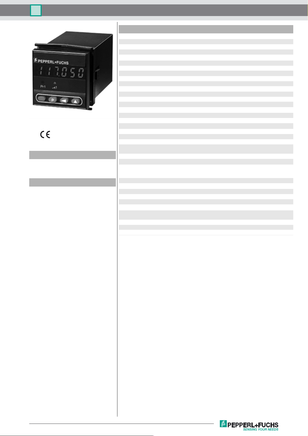
Batch controller KCT1-6SR-C
Technical data
General specifications
Model Number
KCT1-6SR-C
Batch controller
Features
• Counter/Timer/Tachometer
• Counter frequency up to 20 kHz
• 6-digit LED indicator, red
• 1 Pre-selection
• Status LED indication for output an
preselection value
• Display range and preselection range
from -199999 up to 999999
Overflow will be evaluated correctly
up to 1 decade
• Programmable functionality as pulse
counter, frequency counter, timer or
• Relay output
• Adding/subtracting via 2 separate inputs
• PNP and NPN sensors can be connected
• Protection degree IP65 (front only)
Pre-selection single
Data storage 10
Programming keypad-driven menu
Indicators/operating means
Type 7-segment LED display, red
Number of digits 6
Display value digit height 8 mm
Pre-selection switchable
Key interlock with "high"-level at terminal "KEY"
Display interval -99999 ... 999999
Decimal point 0 to max 3 fractional digits
Scale factor 0.0001 ... 99.9999
Reset manually or external
Electrical specifications
Operating voltage UB10 ... 30 V DC
Power consumption P
Input
Counting frequency 20 kHz
Minimum pulse duration 5 ms for reset input
Impedance approx. 10 kOhm
Voltage low: 0 ... 0.2 x Ue
Counting method adding or subtracting
Output
Relay 250 V AC, max. 3 A
Response time 7 ms
Ambient conditions
Ambient temperature -10 ... 50 °C (263 ... 323 K)
Storage temperature -25 ... 70 °C (248 ... 343 K)
Relative humidity ≤ 80 % (non-condensing)
Mechanical specifications
Connection 2 plug-in 7-pin screw terminals
Mass approx. 200 g
Dimensions 48mmx48mmx106mm
Mounting latch fastener (dimension 50.5 mm x 54.5 mm)
6
storage cycles or 10 years
max. 1.2 VA
0
high: 0.6 x U
125 V DC, min. 30 mA
changeover contact
max. core cross-section 0.34 ... 1.5 mm
... 30 V DC
e
2
Release date: 2010-03-01 12:15 Date of issue: 2010-03-01 110347_ENG.xml
Subject to modifications without notice
Copyright Pepperl+Fuchs
1
Page 2
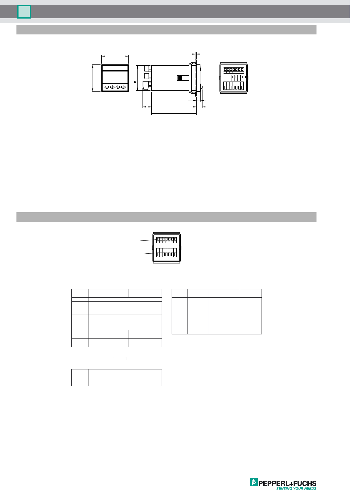
Dimensions
KCT1-6SR-CBatch controller
Electrical connection
48
48
45
max. 10.5
3714562
31452
3714562
7.3
15.5
9.3
80.1
X2
X1
Connector assignment X1
supply voltage and outputs
Terminal
AC version
No.
n.c.
1
n.c.
2
output relay
3
common contact (C)
4
output relay
normally open contact (NO)
5
output relay
normally closed contact (NC)
6
supply voltage
90 ... 250 V AC
7
supply voltage
90 ... 250 V AC
Attention
In the case of selection of and (inverted relay
function) the function of terminals 4 and 5 are changed:
Terminal
AC and DC versions
No.
4
Relay normally closed (NC)
5
Relay normally open (NO)
10 ... 30 V
DC version
operating voltage
10 ... 30 V DC
0 V DC (GND)
3714562
3714562
Connector assignment X2
inputs
Terminal
Name
No.
+24 VDC
1
0 VDC
2
(GND)
3
INP A
4
INP B
5
RESET
6
GATE
7
KEY
AC version
Sensor
Supply voltage
Reference voltage
Counter input A
Counter input B
Reset input
Gate circuit
Input for key locking
10 ... 30 V
DC version
not
connected
not
connected
Subject to modifications without notice
2
Release date: 2010-03-01 12:15 Date of issue: 2010-03-01 110347_ENG.xml
Copyright Pepperl+Fuchs
 Loading...