

Pepperl Fuchs KC-LCDC-48-2T-230VAC Data Sheet
Timer, Counter, Tachometer KC-LCDC-48-2T-230VAC
Model Number
KC-LCDC-48-2T-230VAC
LCD batch controller with 2 optocoupler
outputs and 90 ... 260 V
ge
Features
• Counter/Timer/Tachometer
• Adding/subtracting via 2 separate inputs
• Batch controller with 2 pre-selections
• 2 potential-free optocoupler outputs
• Easy-to-read 2-line LCD display, color, with icons for the displayed preselection and the status of both outputs
• Multicolor display
• Display range and preselection range
from -999999 up to 999999
Overflow will be evaluated correctly
up to 1 decade
• PNP and NPN sensors can be connected
• Degree of protection IP65 (front only)
Release date: 2016-09-12 10:30 Date of issue: 2016-09-12 214738_eng.xml
Refer to “General Notes Relating to Pepperl+Fuchs Product Information”.
supply volta-
AC
Technical data
General specifications
Pre-selection 2-fold
Data storage > 10 years, EEPROM
Programming keypad-driven menu
Functional safety related parameters
MTTFd 410 a
Mission Time (T
Diagnostic Coverage (DC) 0 %
Indicators/operating means
Ty p e 2-line, 2 x 6-digit LC display with leading sign
Display value digit height 9 mm
Pre-selection digit height 7 mm
Key interlock via "high" potential at "LOCK" input
Decimal point 0 to max 5 fractional digits
Scale factor 0.0001 ... 99.9999
Reset manually or external
Electrical specifications
Fusing 90 … 260 V AC: T 0.1 A
Operating voltage U
Power consumption P0max. 8 VA
Input
Connection Counter inputs: A and B
Signal voltage
High 12 ... 30 V DC
Low 0 ... 4 V DC
Counting frequency 30 Hz / 55 kHz
Minimum pulse duration Control/reset inputs: 10 ms / 1 ms
Impedance 5 kOhm
Count modes
Pulse counter Counting with counting direction (cnt.dir),
Frequency counter functions for input A and input B:
Timer Time measurement via GATE input (FrErun),
Output
Sensor supply 20.4 ... 27.6 V DC,
Response time approx. 1 ms
Optocoupler Schaltleistung 30 V DC / 10 mA
Signal voltage U
Ambient conditions
Ambient temperature -20 ... 65 °C (-4 ... 149 °F)
Storage temperature -25 ... 75 °C (-13 ... 167 °F)
Relative humidity ≤ 93 % at 40 °C
Altitude 0 ... 2000 m
Pollution degree 2
Mechanical specifications
Degree of protection IP65 (front)
Mass approx. 134 g
Dimensions 48 mm x 48 mm x 109.8 mm
Compliance with standards and directives
Directive conformity
Low Voltage Directive 2006/95/EC EN 61010-1:2001; protection class: 2
EMC Directive 2004/108/EC EN 61000-6-2:2005, EN 50295:1999
Standard conformity
Emitted interference DIN EN 55011:2009, Class B
Mech. capacity EN 60068-2-6:2008
Shock and impact resistance EN 60068-2-27:1995
) 10 a
M
B
Multicolor, backlit
90 ... 260 V AC
Control/reset inputs: LOCK, RESET, GATE, MPI
difference counting (up.dn),
up/down counting (quad),
Cumulative counting (up.up),
up/down counting x 2 (quad 2),
up/down counting x 4 (quad 4),
additional functions for counter input A and counter input B:
A/B, (A-B)/A x 100%
A, A-B, A+B quad, A/B, (A-B)/A x 100 %
counter input A: Start, counter input B: Stop (InpA.InpB.),
counter input B: Start/Stop (InpB.InpB.),
time measuring via RESET input (auto)
max. 80 mA
with IC = 10 mA: max. 2 V
CESAT
with IC = 5 mA: max. 0.4 V
U
CESAT
(noncondensing)
10 … 55 Hz / 1 mm / XYZ
30 min in each direction
100 G / 2 ms / XYZ
3 times in each direction
1
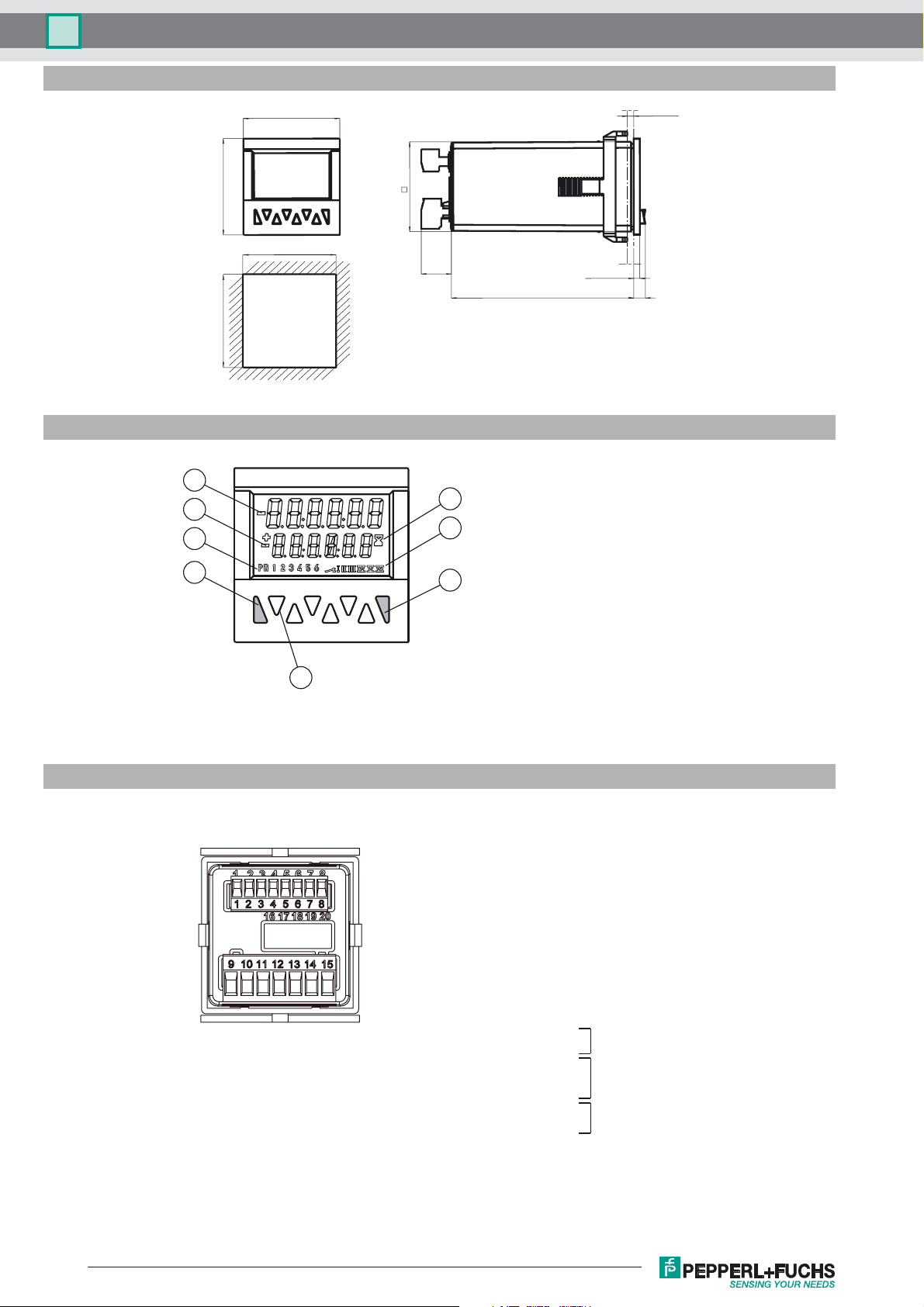
Dimensions
KC-LCDC-48-2T-230VACTimer, Counter, Tachometer
48
+0.6
45
Indicators / Operating means
1
2
3
4
48
45
+0.6
45
13.8
91
2.9
max. 10.5
5
1 Current count value
6
7
2 Preset value
3 Indicator preset value (at 9)
4 Reset key
5 Decade keys 1 to 6 /
Keys for programming
6 Run display for timer
8
7 Shows the active output
8 Prog/Mode key
Electrical connection
5
Signal and control inputs
1 Sensor supply voltage
2 GND (0V)
3 INP A (Signal input A)
4 INP B (Signal input B)
5 RESET (Reset input)
6 LOCK (Input Keypad lock)
7 GATE (Gate input)
8 MPI (User input)
Supply voltage and outputs
9 Collector
10 Emitter
11 Collector
12 not connected
13 Emitter
14 90 ... 260 V AC N~
15 90 ... 260 V AC L~
Output 1
Output 2
Supply
voltage
Refer to “General Notes Relating to Pepperl+Fuchs Product Information”.
2
Release date: 2016-09-12 10:30 Date of issue: 2016-09-12 214738_eng.xml
 Loading...