

Page 1
Switch Amplifier
2
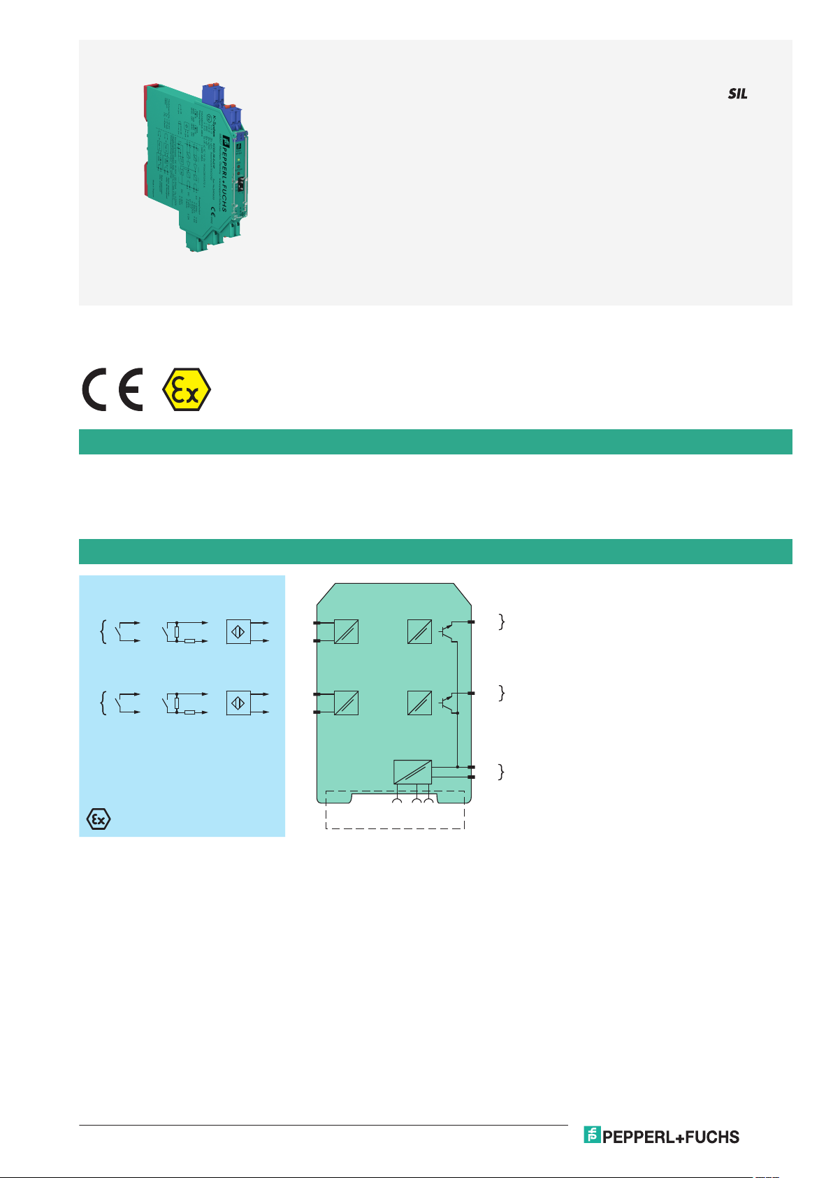
KCD2-ST-Ex2.SP
5+
1+
2-
6+
Zone 0, 1, 2
Div. 1, 2
Zone 2
Div. 2
24 V DC
9+
10-
Power Rail
24 V DCERR
10 kΩ
400 Ω ≤ R ≤ 2 kΩ
3+
4-
10 kΩ
400 Ω ≤ R ≤ 2 kΩ
I
II
I
II
Germany: +49 621 776 2222Pepperl+Fuchs Group
Refer to "General Notes Relating to Pepperl+Fuchs Product Information".
USA: +1 330 486 0002 Singapore: +65 6779 9091
www.pepperl-fuchs.com pa-info@us.pepperl-fuchs.com pa-info@sg.pepperl-fuchs.com
pa-info@de.pepperl-fuchs.com
KCD2-ST-Ex2.SP
2-channel isolated barrier
<
24 V DC supply (Power Rail)
<
Dry contact or NAMUR inputs
<
2 active transistor outputs
<
Reversible mode of operation
<
Line fault detection (LFD)
<
Housing width 12.5 mm
<
Connection via spring terminals with push-in connection
<
technology
Up to SIL 2 acc. to IEC 61508
<
Function
This isolated barrier is used for intrinsic safety applications.
The device transfers digital signals (NAMUR sensors or dry contacts) from a hazardous area to a safe area.
Each input controls an active transistor output.
Via switches the mode of operation can be reversed and the line fault detection can be switched off.
A fault is signalized by LEDs acc. to NAMUR NE44 and a separate collective error message output.
Connection
Release date: 2020-09-23 Date of issue: 2020-09-23 Filename: 242097_eng.pdf
1
Page 2
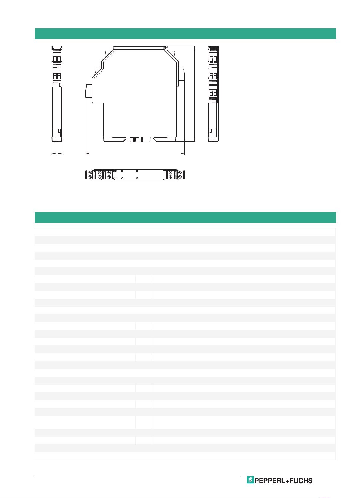
12.5
114
119
Switch Amplifier KCD2-ST-Ex2.SP
Germany: +49 621 776 2222Pepperl+Fuchs Group
Refer to "General Notes Relating to Pepperl+Fuchs Product Information".
USA: +1 330 486 0002 Singapore: +65 6779 9091
www.pepperl-fuchs.com pa-info@us.pepperl-fuchs.com pa-info@sg.pepperl-fuchs.com
pa-info@de.pepperl-fuchs.com
Dimensions
Technical Data
General specifications
Signal type Digital Input
Functional safety related parameters
Safety Integrity Level (SIL) SIL 2
Supply
Connection Power Rail or terminals 9+, 10-
Rated voltage U
Ripple ≤ 10 %
Rated current I
Power dissipation ≤ 800 mW including maximum power dissipation in the output
Input
Connection side field side
Connection terminals 1+, 2-; 3+, 4-
Rated values acc. to EN 60947-5-6 (NAMUR)
Open circuit voltage/short-circuit current approx. 10 V DC / approx. 8 mA
Switching point/switching hysteresis 1.2 ... 2.1 mA / approx. 0.2 mA
Line fault detection breakage I ≤ 0.1 mA , short-circuit I ≥ 6.5 mA
Pulse/Pause ratio min. 100 µs / min. 100 µs
Output
Connection side control side
Connection terminals 5, 6
Rated voltage U
Rated current I
Response time ≤ 200 µs
Signal level 1-signal: (supply voltage) - 3 V max. for 50 mA
Output I signal ; Transistor
Output II signal ; Transistor
Collective error message Power Rail
Transfer characteristics
Release date: 2020-09-23 Date of issue: 2020-09-23 Filename: 242097_eng.pdf
19 ... 30 V DC
r
30 ... 20 mA + I
r
30 V DC
r
50 mA
r
out
0-signal: blocked output (off-state current ≤ 10 µA)
2
Page 3

Switch Amplifier KCD2-ST-Ex2.SP
Germany: +49 621 776 2222Pepperl+Fuchs Group
Refer to "General Notes Relating to Pepperl+Fuchs Product Information".
USA: +1 330 486 0002 Singapore: +65 6779 9091
www.pepperl-fuchs.com pa-info@us.pepperl-fuchs.com pa-info@sg.pepperl-fuchs.com
pa-info@de.pepperl-fuchs.com
Technical Data
Switching frequency ≤ 5 kHz
Galvanic isolation
Input/Output reinforced insulation acc. to EN 50178, rated insulation voltage 300 V
Input/power supply reinforced insulation acc. to EN 50178, rated insulation voltage 300 V
Output/power supply not available , common pole terminal 9+
Output/Output not available , common pole terminal 9+
Indicators/settings
Display elements LEDs
Control elements DIP-switch
Configuration via DIP switches
Labeling space for labeling at the front
Directive conformity
Electromagnetic compatibility
Directive 2014/30/EU EN 61326-1:2013 (industrial locations)
Conformity
Electromagnetic compatibility NE 21:2011
Degree of protection IEC 60529:2001
Protection against electrical shock IEC 61010-1:2010
Input EN 60947-5-6:2000
Ambient conditions
Ambient temperature -20 ... 60 °C (-4 ... 140 °F)
Mechanical specifications
Degree of protection IP20
Connection spring terminals
Mass approx. 100 g
Dimensions 12.5 x 114 x 119 mm (0.5 x 4.5 x 4.7 inch) , housing type A2
Mounting on 35 mm DIN mounting rail acc. to EN 60715:2001
Data for application in connection with hazardous areas
EU-type examination certificate BASEEFA 13 ATEX 0080
Marking 1 II (1)G [Ex ia Ga] IIC
1 II (1)D [Ex ia Da] IIIC
1 I (M1) [Ex ia Ma] I
Input Ex ia
Voltage U
Current I
Power P
10.5 V
o
17.1 mA
o
45 mW (linear characteristic)
o
Supply
Maximum safe voltage U
253 V AC (Attention! Um is no rated voltage.)
m
Output
Maximum safe voltage U
253 V AC (Attention! The rated voltage can be lower.)
m
Certificate CML 19 ATEX 4410 X
Marking 1 II 3G Ex ec IIC T4 Gc
Galvanic isolation
Input/Output safe electrical isolation acc. to IEC/EN 60079-11, voltage peak value 375 V
Input/power supply safe electrical isolation acc. to IEC/EN 60079-11, voltage peak value 375 V
Directive conformity
Directive 2014/34/EU EN IEC 60079-0:2018 , EN 60079-7:2015+A1:2018 , EN 60079-11:2012
International approvals
UL approval
Control drawing 116-0374 (cULus)
IECEx approval IECEx BAS 13.0046
IECEx CML 19.0147X
Approved for [Ex ia Ga] IIC, [Ex ia Da] IIIC, [Ex ia Ma] I
Ex ec IIC T4 Gc
Release date: 2020-09-23 Date of issue: 2020-09-23 Filename: 242097_eng.pdf
eff
eff
3
Page 4

KCD2-ST-
Ex2
PWR
1 2
3
4
9
10
867
5
S1
S3
S4
S2
III
OUT/CHK
1
2
Front view
LED green:
Power supply
Removable spring terminals
green
Removable spring terminals
blue
Place for labeling
Switch 1 ... 4
LED yellow/red:
Status output/
Fault signal channel I
LED yellow/red:
Status output/
Fault signal channel II
Switch Amplifier KCD2-ST-Ex2.SP
Germany: +49 621 776 2222Pepperl+Fuchs Group
Refer to "General Notes Relating to Pepperl+Fuchs Product Information".
USA: +1 330 486 0002 Singapore: +65 6779 9091
www.pepperl-fuchs.com pa-info@us.pepperl-fuchs.com pa-info@sg.pepperl-fuchs.com
pa-info@de.pepperl-fuchs.com
Technical Data
General information
Supplementary information Observe the certificates, declarations of conformity, instruction manuals, and manuals
where applicable. For information see www.pepperl-fuchs.com.
Accessories
Optional accessories - power feed module KFD2-EB2(.R4A.B)(.SP)
- universal power rail UPR-03(-M)(-S)
- profile rail K-DUCT-BU(-UPR-03)
Assembly
Accessories
Release date: 2020-09-23 Date of issue: 2020-09-23 Filename: 242097_eng.pdf
KFD2-EB2 Power Feed Module
KFD2-EB2.R4A.B Power feed module, redundant supply
KFD2-EB2.R4A.B.SP Power feed module with spring terminals, redundant supply
KFD2-EB2.SP Power feed module with spring terminals
UPR-03 Universal Power Rail with end caps and cover, 3 conductors, length: 2 m
UPR-03-M Universal Power Rail with end caps and cover, 3 conductors, length: 1,6 m
UPR-03-S Universal Power Rail with end caps and cover, 3 conductors, length: 0.8 m
K-DUCT-BU
4
Page 5

Switch Amplifier KCD2-ST-Ex2.SP
Germany: +49 621 776 2222Pepperl+Fuchs Group
Refer to "General Notes Relating to Pepperl+Fuchs Product Information".
USA: +1 330 486 0002 Singapore: +65 6779 9091
www.pepperl-fuchs.com pa-info@us.pepperl-fuchs.com pa-info@sg.pepperl-fuchs.com
pa-info@de.pepperl-fuchs.com
Accessories
K-DUCT-BU-UPR-03 Profile rail with UPR-03- * insert, 3 conductors, wiring comb field side blue
Release date: 2020-09-23 Date of issue: 2020-09-23 Filename: 242097_eng.pdf
5
Page 6

Germany: +49 621 776 2222Pepperl+Fuchs Group
Refer to "General Notes Relating to Pepperl+Fuchs Product Information".
USA: +1 330 486 0002 Singapore: +65 6779 9091
www.pepperl-fuchs.com pa-info@us.pepperl-fuchs.com pa-info@sg.pepperl-fuchs.com
pa-info@de.pepperl-fuchs.com
Switch Amplifier
S1
S3
S4
IIS2I
S1
S3
S4
IIS2I
Configuration
KCD2-ST-Ex2.SP
Switch settings
SFunction Position
1 Mode of operation output I (active) with high input current I
with low input current II
2 Mode of operation output II (active) with high input current I
with low input current II
3 Line fault detection of the input I ON I
OFF II
4 Line fault detection of the input II ON I
OFF II
Operating states
Control circuit Input signal
Initiator high impedance/contact opened low input current
Initiator low impedance/contact closed high input current
Lead breakage, lead short circuit Line fault
Factory setting: switch 1, 2, 3 and 4 in position I
Release date: 2020-09-23 Date of issue: 2020-09-23 Filename: 242097_eng.pdf
6
 Loading...