

Page 1
Your automation, our passion.
K23-SSI/Rx/IU-C
Signal converter
Manual
Page 2

K23-SSI/Rx/IU-C
The latest version of the General Terms of Supply for Products
and Services in the Electronics Industry set out by the German
Electrical and Electronic Manufacturers' Association (ZVEI) and
the "Extended Reservation of Proprietorship" supplementary
clause apply to this document.
2
Page 3

| TABLE OF CONTENTS
Table of Contents
1. Safety and Responsibility ......................................................................................................... 5
1.1 General Safety Information ................................................................................................ 5
1.2 Intended Use ..................................................................................................................... 5
1.3 Installation ......................................................................................................................... 6
1.4 Cleaning, Care, and Maintenance Instructions .................................................................. 6
2. General Information .................................................................................................................. 7
2.1 Operating Modes ............................................................................................................... 7
2.2 Function Diagram .............................................................................................................. 7
2.3 Power LED / Error Messages ............................................................................................ 7
3. Electrical Connections .............................................................................................................. 9
3.1 DC Voltage Supply (X1)..................................................................................................... 9
3.2 Auxiliary Voltage Output (X2) ............................................................................................ 9
3.3 Incremental Rotary Encoder Input (X2) ............................................................................ 10
3.4 Absolute Rotary Encoder Input (X2) ................................................................................ 12
3.5 Start/Stop Encoder Inputs (X2) ........................................................................................ 13
3.6 Control Inputs (X5) .......................................................................................................... 14
3.7 Analog Output (X4) .......................................................................................................... 16
3.8 Serial Interface (X3) ......................................................................................................... 16
3.9 Control Outputs (X6) ........................................................................................................ 17
3.10 USB Interface (X7) .......................................................................................................... 18
4. Operating Software OS6.0 / OS10.0 ....................................................................................... 19
4.1 General Menu .................................................................................................................. 22
4.2 Frequency Mode ............................................................................................................. 25
4.3 Counter Mode .................................................................................................................. 31
4.4 SSI Mode ........................................................................................................................ 33
4.5 Start/Stop Mode .............................................................................................................. 36
4.6 Preselection Values ......................................................................................................... 40
4.7 Preselection 1 Menu ........................................................................................................ 41
4.8 Preselection 2 Menu ........................................................................................................ 45
4.9 Preselection 3 Menu ........................................................................................................ 46
4.10 Preselection 4 Menu ........................................................................................................ 47
4.11 Preselection 5 Menu ........................................................................................................ 49
4.12 Preselection 6 Menu ........................................................................................................ 50
4.13 Serial Menu ..................................................................................................................... 51
4.14 Analog Menu ................................................................................................................... 54
4.15 Command Menu .............................................................................................................. 56
4.16 Linearization Menu .......................................................................................................... 59
3
Page 4

5. Appendix ................................................................................................................................. 60
5.1 Reading Out Data via Serial Interface .............................................................................. 60
5.2 Modbus RTU Interface ..................................................................................................... 61
5.2.1 Parameter Settings ................................................................................................... 61
5.2.2 Read Holding Registers and Write Multiple Registers ............................................... 62
5.2.3 Read Coils and Write Single Coil .............................................................................. 64
5.2.4 Diagnostics ............................................................................................................... 65
5.3 Parameter List / Serial Codes .......................................................................................... 65
5.4 Serial Codes of the Commands ....................................................................................... 74
5.5 Linearization .................................................................................................................... 74
5.6 Reading in the SSI Value ................................................................................................. 77
5.7 Operating Modes / OP Modes of the Start/Stop Interface ................................................. 81
5.8 Dimensions ...................................................................................................................... 83
4
Page 5

| SAFETY AND RESPONSIBILITY
1. Safety and Responsibility
1.1 General Safety Information
This description is an essential part of the device and contains important
information regarding installation, function and use. Failure to observe these
instructions may result in damage or impair the safety of people and attachments.
Please read this description carefully and observe all safety and warning
messages before commissioning the device for the first time. Keep this
description for future reference.
A prerequisite for using this device description is that the relevant personnel have
the appropriate qualifications. The device may be installed, configured,
commissioned and maintained only by a trained electrician.
Exclusion of liability: The manufacturer is not liable for any personal injury or
property damage that may occur as a result of improper installation,
commissioning, use or servicing, or due to human misinterpretations or errors
within this device description. In addition, the manufacturer reserves the right to
make technical changes to the device or description at any time without prior
notice. Therefore, possible discrepancies between the device and the description
cannot be ruled out.
The safety of the plant or of the overall system in which this device is integrated is
the responsibility of the installer of the plant or the overall system.
All general, country-specific, and application-specific safety regulations and
standards must be observed and followed during installation, operation, and
maintenance work.
If the device is used in processes in which a possible failure or incorrect
operation can result in damage to the plant or personal injury, appropriate
precautions must be taken to ensure that such consequences are safely
prevented.
1.2 Intended Use
This device is intended for use in industrial machinery and plants only. Any other
use is not deemed to be in compliance with the provisions and is solely the
responsibility of the user. The manufacturer is not liable for damage caused by
improper use. The device may only be installed in the correct manner and be
used and operated in a technically perfect condition—in accordance with the
technical data. The device is not suitable for explosion-protected areas or in
areas of application not included in DIN EN 61010-1.
5
Page 6

| SAFETY AND RESPONSIBILITY
1.3 Installation
The device may only be installed and operated in an environment that meets the
permissible temperature range. Adequate ventilation must be ensured and the
device must not have any direct contact with hot or aggressive gases or liquids.
The unit must be disconnected from all voltage sources prior to installation and
before any maintenance work. It must also be ensured that no further danger can
arise from touching the disconnected voltage sources.
Devices that are supplied with AC voltage may only be connected to the lowvoltage network via switches or circuit breakers. This switch must be positioned
close to the device and must have a marking that identifies it as a disconnector.
Input and output cables for extra-low voltages must be separated from
dangerous, current-carrying cables by means of double or reinforced insulation
(SELV circuits).
All cables and insulation selected must correspond to the intended voltage and
temperature range. Device and country-specific standards must also be
observed, which apply to the cables in terms of design, shape, and quality. For
information on permissible cable cross sections for the screw terminal
connections, refer to the technical data.
Before commissioning, all connections and cables must be checked for a solid fit
in the screw terminals. All screw terminals (including unused ones) must be
screwed in as far as they will go to ensure that they are securely fastened and
cannot come loose in the event of mechanical vibrations.
Overvoltages at the connections to the device must be limited to the values of the
gas group II overvoltage category.
The general standards for switch cabinet construction in the machinery industry
and the manufacturer's specific shielding regulations apply with regard to
installation, wiring, ambient conditions, and shielding and grounding of supply
cables.
1.4 Cleaning, Care, and Maintenance Instructions
To clean the front, use only a soft, slightly damp cloth. No cleaning work is
intended or required for the rear of the device. Unscheduled cleaning is the
responsibility of the competent maintenance personnel or the relevant technician.
During normal operation, the device does not require any maintenance
procedures. In the event of unexpected problems, errors or malfunctions, the
device must be sent to the manufacturer to be checked and repaired if
necessary. Unauthorized opening and repair can result in impairment or even
failure of the protective measures supported by the device.
6
Page 7
2. General Information
The device is designed as a signal converter with control inputs and outputs. Its
extensive functions make it suitable for universal use.
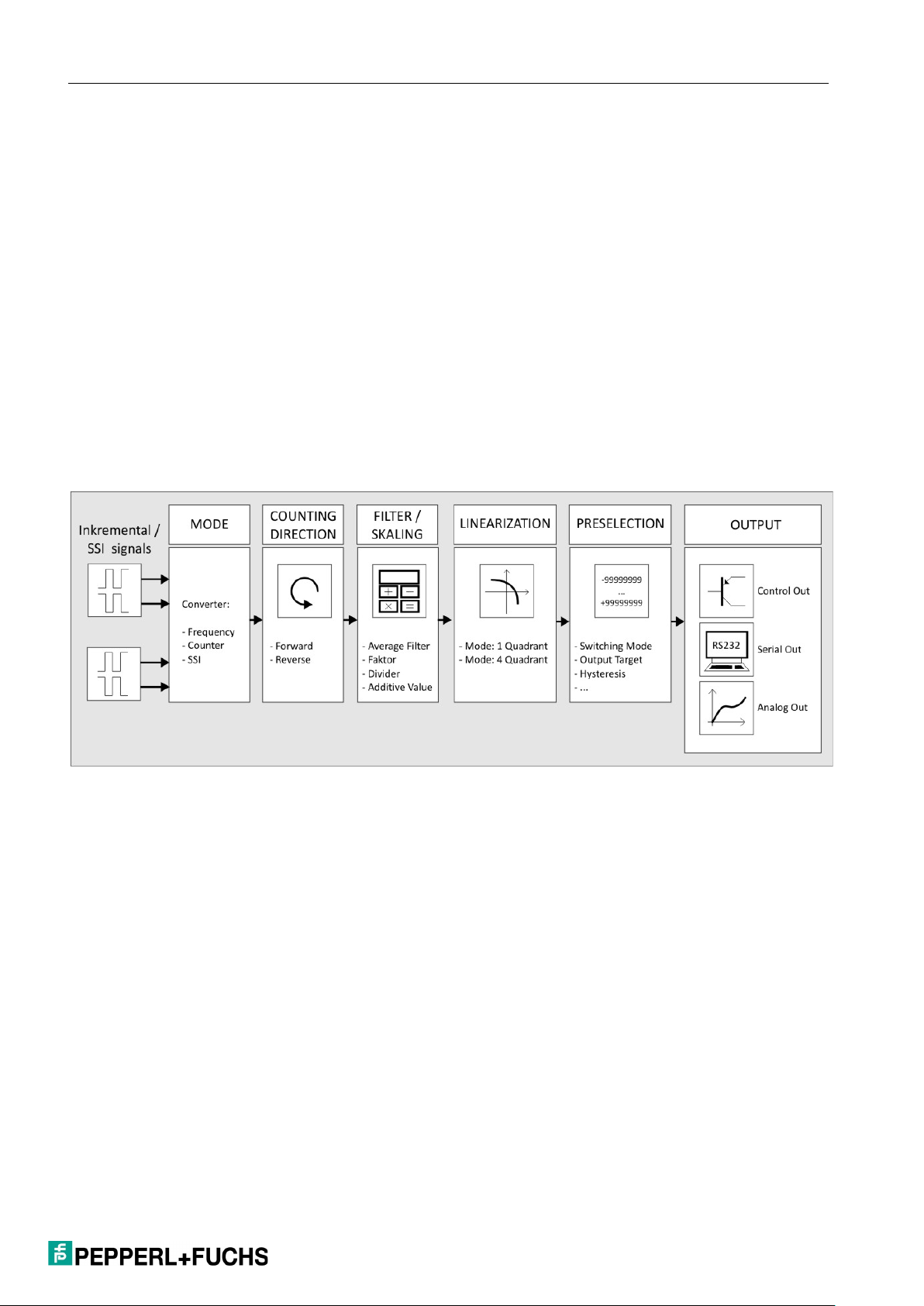
2.1 Operating Modes
In general, all functions must be configured in the parameter menu. The device
can be used in the following operating modes:
Operation as a frequency converter for incremental input signals
Operation as a position converter/counter for incremental input signals
Operation as an absolute value converter for SSI signals
2.2 Function Diagram
| GENERAL INFORMATION
2.3 Power LED / Error Messages
The device has a green LED on the front film. This lights up continuously as soon
as the supply voltage of the device has been established. If an error occurs, the
LED flashes in a 1-Hz cycle. The analog output is also modulated with 0 V or
0/4 mA. When there is no longer an error, the LED automatically lights up
continuously again and the analog output reacts once more to the result currently
pending.
The exact error can be read out on the user interface (OS 6.0) via the serial
interface. ( Variable: Error_Status, Code: ";3"). See Chapter 4.
7
Page 8

| GENERAL INFORMATION
Error code
(Error_Status)
Error name
Error description
0x00000001
Maximum Value
Measured value is greater than
0x00000002
Minimum Value
Measured value is less than 0x00000004
SSI Encoder Error
SSI Error bit set
0x00000010
Frequency (Input A)
The maximum or minimum
0x00000020
Frequency (Input B)
The maximum or minimum
The individual error codes are explained in more detail below:
99,999,999
99,999,999
out of range
permissible input frequency at input
A was exceeded or not reached with
the exponential filter setting used.
out of range
permissible input frequency at input
B was exceeded or not reached with
the exponential filter setting used.
8
Page 9
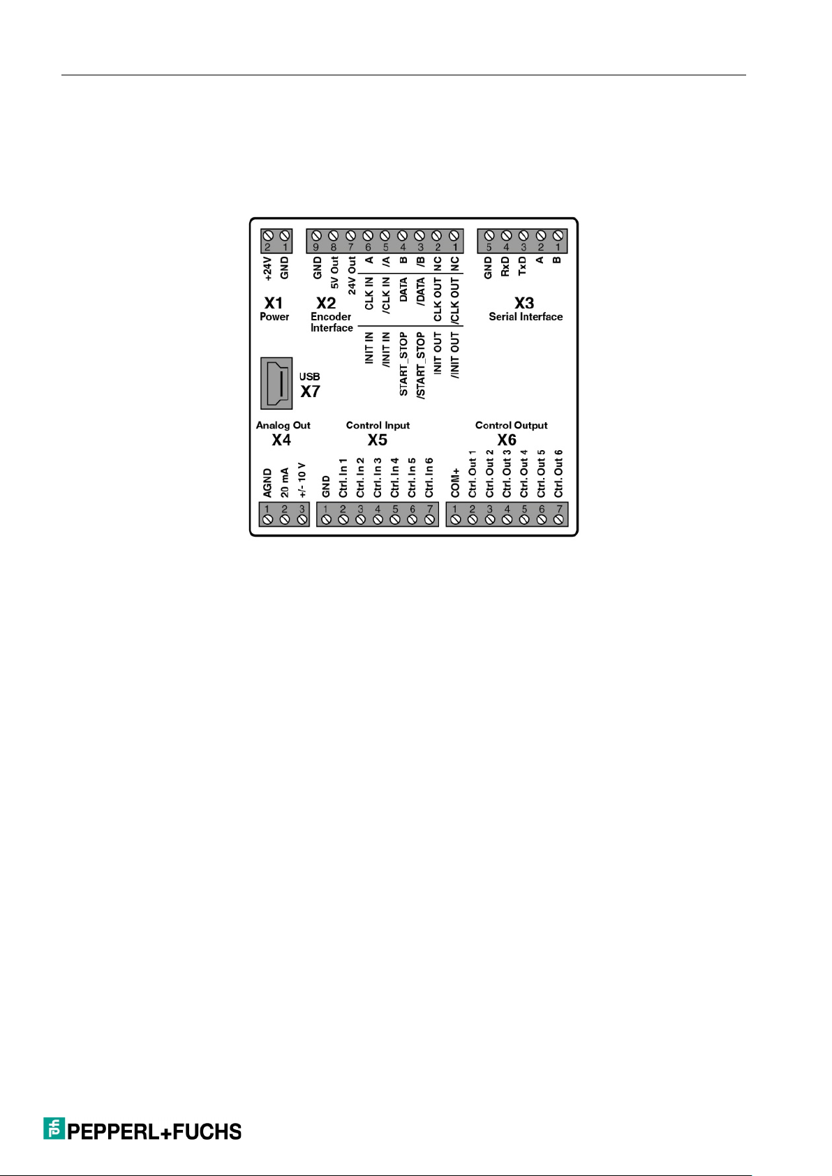
3. Electrical Connections
The terminals should be tightened with a slotted screwdriver (blade width 2 mm).
| ELECTRICAL CONNECTIONS
3.1 DC Voltage Supply (X1)
The device can be supplied with a DC voltage between 18 and 30 V DC via
terminal X1 pins 1 and 2. The current consumption depends, among other things,
on the level of the supply voltage and the settings and is approx. 50 mA, plus the
rotary encoder current taken from the auxiliary voltage output.
All GND connections are connected internally.
3.2 Auxiliary Voltage Output (X2)
Two auxiliary voltages 24 V DC and 5 V DC are available as encoder/sensor
supply at terminal X2 pins 7, 8, and 9. The 24-V DC output voltage depends on
the device supply (see Technische Daten).
9
Page 10
| ELECTRICAL CONNECTIONS
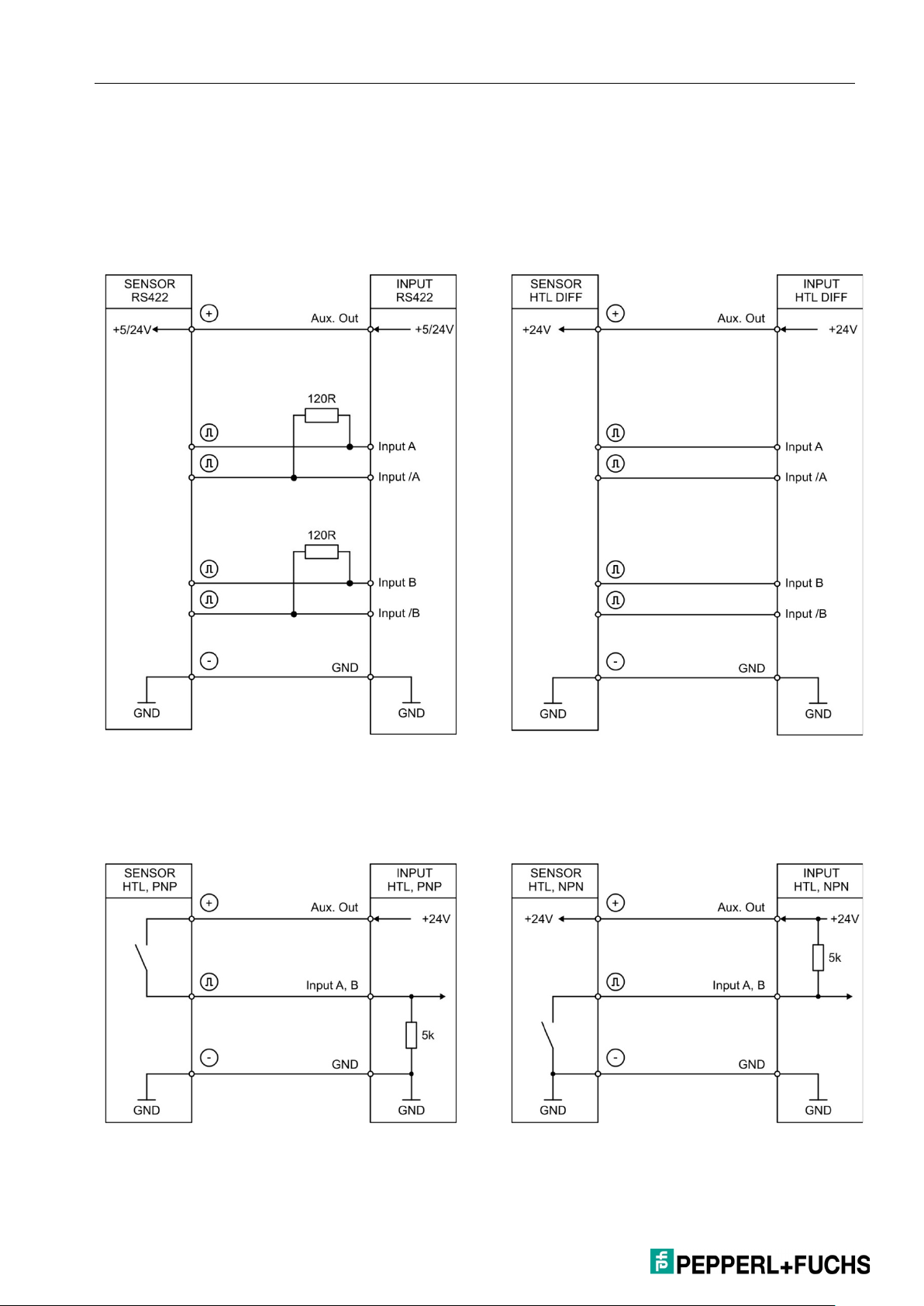
RS422
HTL DIFFERENTIAL
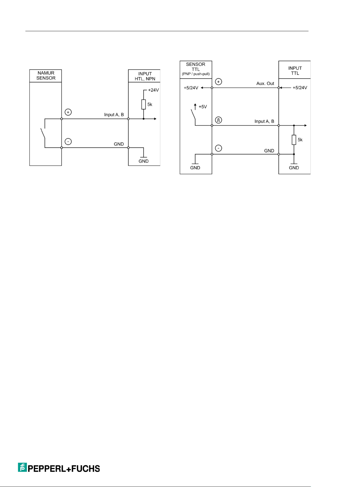
3.3 Incremental Rotary Encoder Input (X2)
A connection for various incremental signals is available at terminal X2 pins 3, 4,
5, and 6.
HTL PNP
HTL NPN
10
Page 11
| ELECTRICAL CONNECTIONS
HTL NPN (NAMUR)
TTL (PNP)
In general, open PNP inputs are "LOW" and open NPN inputs are "HIGH."
The input stages are designed for electronic pulse generators.
Note for mechanical switching contacts:
If, in exceptional cases, mechanical contacts are to be used as a pulse source, a
commercially available external capacitor of approx. 10 µF must be installed at
the terminals between GND(-) and the corresponding input (+). This attenuates
the maximum input frequency to approximately 20 Hz and suppresses bouncing.
11
Page 12
| ELECTRICAL CONNECTIONS
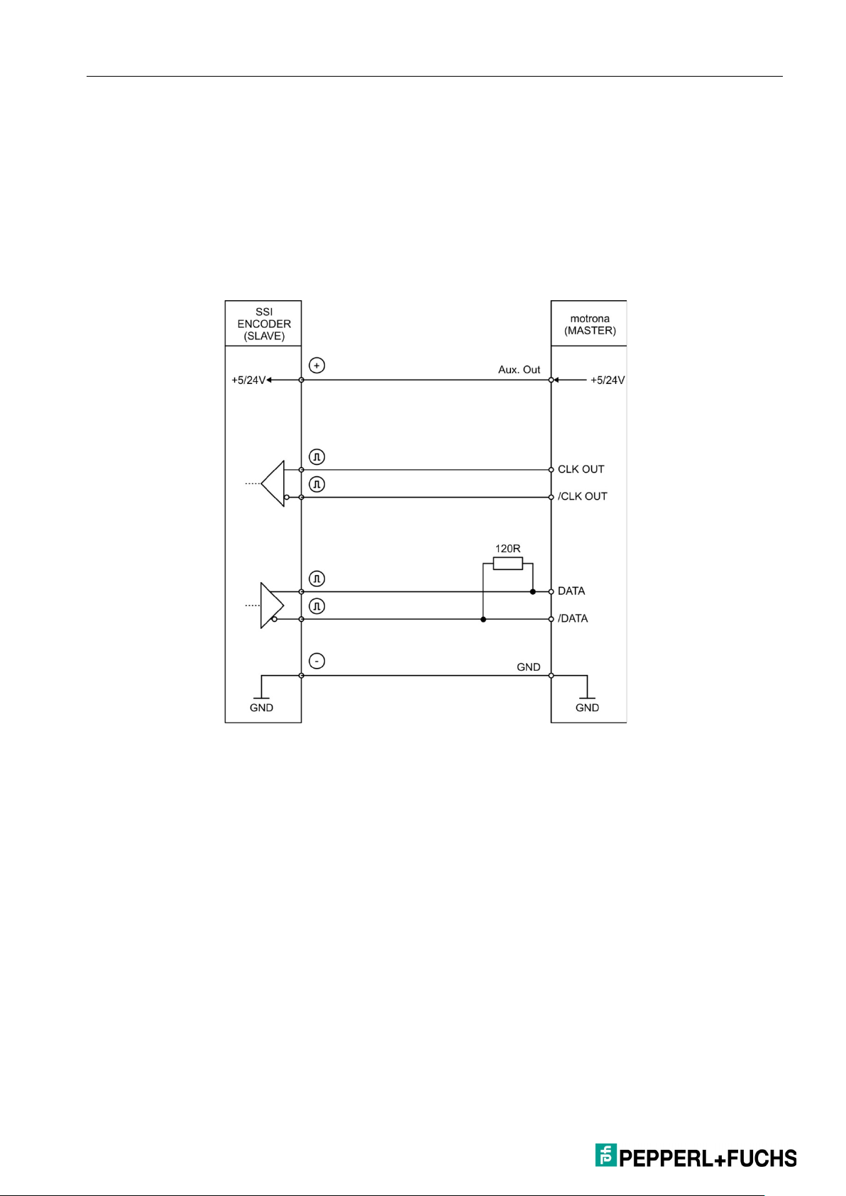
3.4 Absolute Rotary Encoder Input (X2)
The SSI connection is available for managing operation at terminal X2 pins 1, 2,
3, 4.
The SSI connection is available for managed operation at terminal X2 pins 3, 4, 5,
6.
Connection for managing operation:
12
Page 13
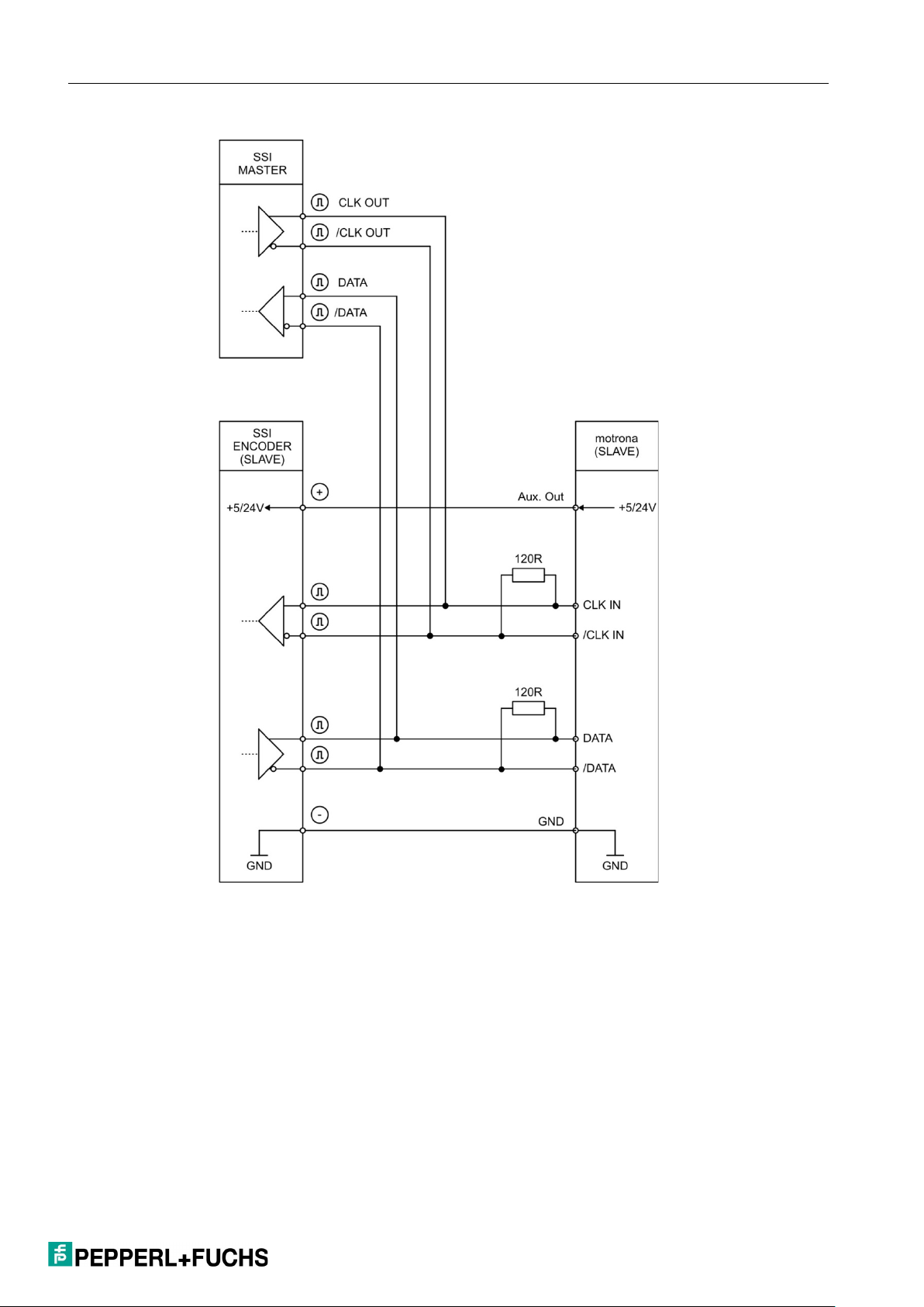
Connection for managed operation:
| ELECTRICAL CONNECTIONS
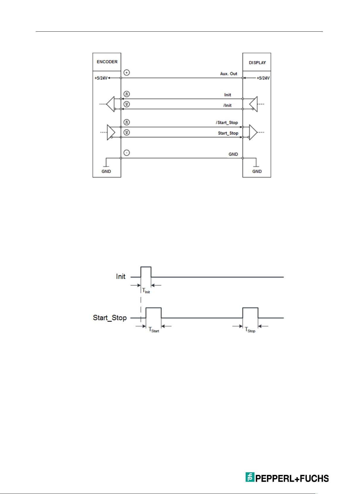
3.5 Start/Stop Encoder Inputs (X2)
The RS422 connection is available for the init pulse in managing operation at
terminal X2 pins 1+2. The device generates the init pulse.
The RS422 connection is available for the init pulse in managed operation at
terminal X2 pins 5+6. The init pulse is generated by an external device.
The RS422 connection is available for the Start/Stop pulse at terminal X2 pins
3+4.
13
Page 14
| ELECTRICAL CONNECTIONS
Connection of the RS422 signals
DPI measurement mode:
In managing operation, the init pulse is sent at regular intervals (=SAMPLING
TIME [ms]) on the init line to the displacement transducer, the rising edge of
which triggers a measurement.
The pulse duration of the init pulse can be set using the "INIT pulse TIME (µs)"
parameter.
T
: 1 µs … 9 µs (adjustable)
Init
T
: ~3 µs … 5 µs
Start
T
: ~3 µs … 5 µs
Stop
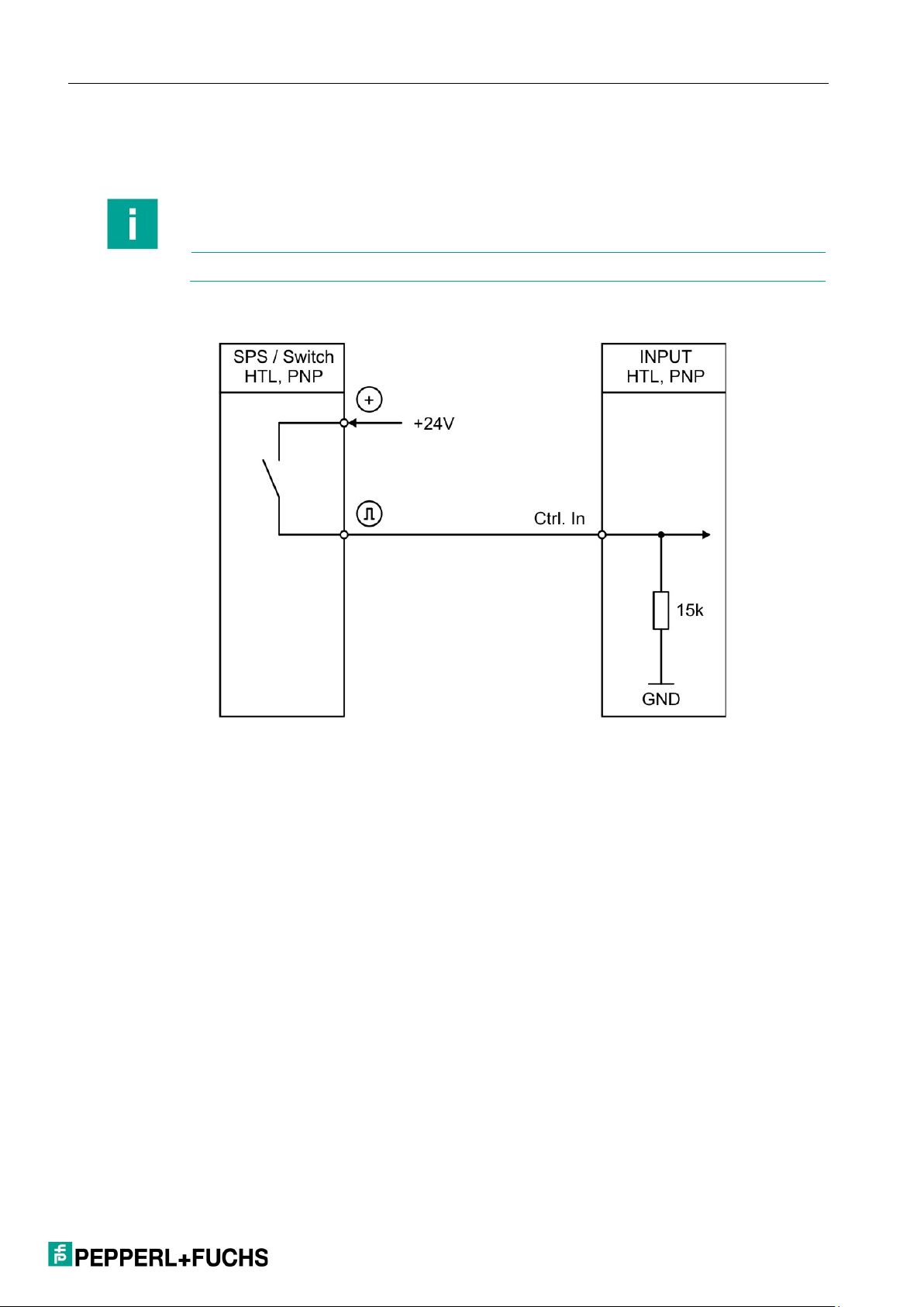
3.6 Control Inputs (X5)
Six control inputs with HTL-PNP characteristics are available at terminal X5 pins
2, 3, 4, 5, 6, and 7.
Control input 1 (Ctrl. In 1) to control input 5 (Ctrl. In 5) are freely configurable in
the COMMAND menu and are used for externally triggered functions such as
releasing the self-locking mechanism, resetting the measurement result, or for
14
Page 15
| ELECTRICAL CONNECTIONS
Note
An HTL pulse (rising edge) at Ctrl. In 6 resets the device to factory settings.
teaching the preselection values or the analog output.
Control input 6 (Ctrl. In 6) is used exclusively for resetting the device parameters
to the "default" values and is therefore not freely configurable.
Connection of the control inputs:
Generally, open control inputs are "LOW."
The input stages are designed for electronic control signals.
Note for mechanical switching contacts:
With mechanical contacts as a pulse source, a commercially available external
capacitor of approx. 10 µF must be installed between GND(-) and the
corresponding input (+). This attenuates the maximum input frequency to
approximately 20 Hz and suppresses bouncing.
15
Page 16

| ELECTRICAL CONNECTIONS
CAUTION!
Parallel operation of voltage and current output is not permitted!
3.7 Analog Output (X4)
A 16-bit analog output is available at terminal X4.
This output can be configured and scaled in the ANALOG MENU.
The following configuration is possible:
Voltage output: -10 V … +10 V
Current output: 0 mA … 20 mA
Current output: 4 mA … 20 mA
The analog output is proportional to the measurement result and refers to AGND
potential.
AGND and device GND are connected internally.
3.8 Serial Interface (X3)
A serial interface (RS232 or RS485) is available at terminal X3.
This interface can be configured in the SERIAL MENU.
The RS232 or RS485 interface can be used as follows:
For parameterization of the device during commissioning
For changing parameters during operation
For reading out actual values via PLC or PC
Connection of the RS232 interface:
16
Page 17
Connection of the RS485 interface:
CAUTION!
Parallel operation of RS232 and RS485 is not permitted!
Default values: 9600 baud, 7even1
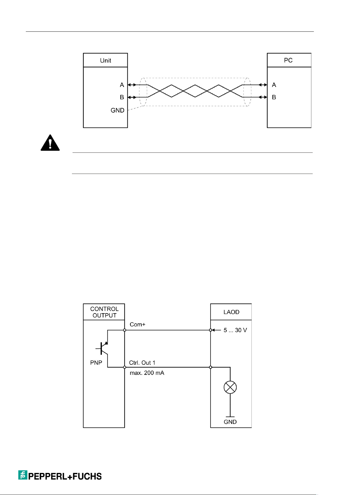
3.9 Control Outputs (X6)
| ELECTRICAL CONNECTIONS
Six control outputs are available at terminal X6 pins 2, 3, 4, 5, 6, and 7.
The switch conditions can be adjusted accordingly in the PRESELECTION
MENU.
Outputs Ctrl. Out 1–6 are quick PNP control outputs.
The switching voltage is determined by the voltage supplied to terminal X6 pin 1
(COM+).
External attenuation measures are recommended for switching inductive loads.
Connection of the control outputs:
17
Page 18

| ELECTRICAL CONNECTIONS
Note
The serial USB communication is carried out at a baud rate of "115200 baud" and a
serial data format of "
These values cannot be changed by the user!
3.10 USB Interface (X7)
A serial USB interface (mini USB) is available at terminal X7.
The USB interface can be used as follows:
For parameterization of the device during commissioning
For changing parameters during operation
For reading out actual values via PC
8none1."
18
Page 19

| OPERATING SOFTWARE OS6.0 / OS10.0
Menu
Parameter
GENERAL MENU
MODE
FACTORY SETTINGS
FREQUENCY MODE
FREQUENCY MODE
AVERAGE FILTER 2
COUNTER MODE
COUNT MODE
ROUND LOOP VALUE
SSI MODE
SSI MODE
4. Operating Software OS6.0 /
OS10.0
The device is parameterized:
via the serial interface using a PC and the OS6.0 operating software.
via the USB interface using a PC and the OS10.0 operating software.
The free operating software OS6.0 and OS10.0 can be found at
Fuchs.com
This section shows the overview of the individual menus and their parameters.
ENCODER PROPERTIES
ENCODER DIRECTION
FACTOR
DIVIDER
ADDITIVE VALUE
LINEARIZATION MODE
BACKUP MEMORY
FREQUENCY BASE
Pepperl-
SAMPLING TIME 1 (S)
WAIT TIME 1 (S)
STANDSTILL TIME 1 (S)
AVERAGE FILTER 1
SAMPLING TIME 2 (S)
WAIT TIME 2 (S)
FACTOR A
SET VALUE A
FACTOR B
SET VALUE B
19
Page 20

| OPERATING SOFTWARE OS6.0 / OS10.0
Menu
Parameter
ENCODER RESOLUTION
ERROR POLARITY
PRESELECTION VALUES
PRESELECTION 1
PRESELECTION 6
PRESELECTION 1 MENU
MODE 1
STARTUP DELAY 1 (S)
PRESELECTION 2 MENU
MODE 2
PRESELECTION 3 MENU
MODE 3
DATA FORMAT
BAUD RATE
SSI ZERO
HIGH BIT
LOW BIT
SSI OFFSET
ROUND LOOP VALUE
SAMPLING TIME (S)
ERROR BIT
PRESELECTION 2
PRESELECTION 3
PRESELECTION 4
PRESELECTION 5
HYSTERESIS 1
PULSE TIME 1 (S)
OUTPUT TARGET 1
OUTPUT POLARITY 1
OUTPUT LOCK 1
HYSTERESIS 2
PULSE TIME 2 (S)
OUTPUT TARGET 2
OUTPUT POLARITY 2
20
OUTPUT LOCK 2
STARTUP DELAY 2 (S)
HYSTERESIS 3
PULSE TIME 3 (S)
OUTPUT TARGET 3
OUTPUT POLARITY 3
OUTPUT LOCK 3
Page 21

| OPERATING SOFTWARE OS6.0 / OS10.0
Menu
Parameter
STARTUP DELAY 3 (S)
PRESELECTION 4 MENU
MODE 4
STARTUP DELAY 4 (S)
PRESELECTION 5 MENU
MODE 5
STARTUP DELAY 5 (S)
PRESELECTION 6 MENU
MODE 6
STARTUP DELAY 6 (S)
SERIAL MENU
UNIT NUMBER
MODBUS
ANALOG MENU
ANALOG FORMAT
COMMAND MENU
INPUT 1 ACTION
HYSTERESIS 4
PULSE TIME 4 (S)
OUTPUT TARGET 4
OUTPUT POLARITY 4 (S)
OUTPUT LOCK 4
HYSTERESIS 5
PULSE TIME 5 (S)
OUTPUT TARGET 5
OUTPUT POLARITY 5
OUTPUT LOCK 5
HYSTERESIS 6
PULSE TIME 6 (S)
OUTPUT TARGET 6
OUTPUT POLARITY 6
OUTPUT LOCK 6
SERIAL BAUD RATE
SERIAL FORMAT
SERIAL INIT
SERIAL PROTOCOL
SERIAL TIMER (S)
SERIAL VALUE
ANALOG START
ANALOG END
ANALOG GAIN (%)
ANALOG OFFSET (%)
INPUT 1 CONFIG
21
Page 22

| OPERATING SOFTWARE OS6.0 / OS10.0
Menu
Parameter
INPUT 2 ACTION
LINEARIZATION MENU
P1(X)
Value
Designation
Function
0
NOT DEFINED
Operating mode: Not defined, modulation and
measurement results are zero
1
FREQUENCY
Operating mode: Frequency converter,
2
COUNTER
Operating mode: Counter, incremental signals
3
SSI
Operating mode: Absolute value converter, SSI
4
START/STOP
Operating mode: Start/Stop interface converter
INPUT 2 CONFIG
INPUT 3 ACTION
INPUT 3 CONFIG
INPUT 4 ACTION
INPUT 4 CONFIG
INPUT 5 ACTION
INPUT 5 CONFIG
INPUT 6 ACTION (FACTORY SETTINGS)
INPUT 6 CONFIG (RISING EDGE)
P1(Y)
P2(X)
4.1 General Menu
MODE (operating mode)
This parameter defines which measurement function (operating mode/mode) the
device should fulfill.
P2(Y)
…
…
P23(X)
P23(Y)
P24(X)
P24(Y)
22
incremental signals (replaces FU252)
(replaces ZU252)
signals (replaces IV251)
Page 23

| OPERATING SOFTWARE OS6.0 / OS10.0
Value
Designation
Function
0
RS422
RS422 standard
HTL
DIFFERENTIAL
2
HTL PNP
PNP (switching to +)
3
HTL NPN
NPN (switching to -)
4
TTL PNP
TTL PNP (switching to +)
Value
Designation
Function
0
FORWARD
Forward
1
REVERSE
Backward
Value
Function
-99999999
Smallest value
1
Default value
99999999
Largest value
Value
Function
-99999999
Smallest value
1
Default value
99999999
Largest value
ENCODER PROPERTIES
This parameter defines the characteristics of the incremental input.
1
HTL differential
ENCODER DIRECTION
This parameter reverses the direction of counting and/or travel.
FACTOR (multiplication factor)
This parameter defines the factor by which the measurement result is
multiplied.
DIVIDER (division factor)
This parameter defines the divisor by which the measurement result is divided.
23
Page 24

| OPERATING SOFTWARE OS6.0 / OS10.0
Value
Function
-99999999
Smallest value
0
Default value
99999999
Largest value
Value
Designation
Function
0
OFF
No linearization
1
1 QUADRANT
Linearization in the first quadrant
2
4 QUADRANT
Linearization in all four quadrants
Value
Designation
Function
0
NO
No retentive memory
1
YES
Retentive memory active. Stores the actual
Value
Designation
Function
0
NO
The factory settings are not loaded
1
YES
The factory settings are loaded
ADDITIVE VALUE (additive constant)
This parameter defines an additive constant, which is added to the
measurement result.
LINEARIZATION MODE
This parameter defines the linearization function. Note the information in
the appendix!
BACKUP MEMORY (retentive memory)
FACTORY SETTINGS
value of the counter readings in the event of a
power failure and "counter" mode is switched on.
24
Page 25

4.2 Frequency Mode
Value
Designation
Function
0
A ONLY
Single-channel frequency measurement (only for
channel A).
1
RATIO
Frequency ratio of both channels (channel B /
decimal places in the format +/- x.xxxx
2
PERCENT
Percentage deviation from channel B to channel
places in the format +/- xxx.xx %
3
A + B
Frequency addition of both channels (channel A
+ channel B)
4
A - B
Frequency subtraction of both channels
(channel A - channel B)
5
A/B x 90°
Frequency measurement with A/B x 90° signal.
monitoring)
Value
Function
0
1 Hz
(Interpretation of result in format: xxxxxxxx Hz)
1
1/10 Hz
(Interpretation of result in format: xxxxxxx.x Hz)
2
1/100 Hz
(Interpretation of result in format: xxxxxx.xx Hz)
3
1/1000 Hz
(Interpretation of result in format: xxxxx.xxx Hz)
In this menu, the operation is defined as a frequency converter (incremental
signals). Depending on the operating mode set, only channel A or both channels
(channel A and channel B) are active.
FREQUENCY MODE
This parameter determines which operating mode of the frequency measurement
is desired.
| OPERATING SOFTWARE OS6.0 / OS10.0
channel A).
Note: Interpretation of the result with four
A.
Note: Interpretation of the result with two decimal
(Forward/backward—rotation direction
FREQUENCY BASE
Sets the desired base for frequency measurement (resolution).
25
Page 26
| OPERATING SOFTWARE OS6.0 / OS10.0
Value
Function
0.001
Minimum measuring time in seconds
0.1
Default value
9.999
Maximum measuring time in seconds
Value
Function
0.01
Frequency = 0 Hz for frequencies less than 100 Hz
1.00
Default value
79.99
Frequency = 0 Hz for frequencies less than ~ 0.01 Hz
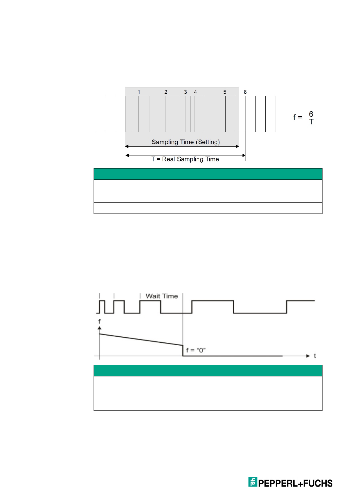
SAMPLING TIME 1 (S)
The set value is the minimum measuring time (for channel A) in seconds. The
sampling time acts as a filter for irregular frequencies. This parameter directly
affects the reaction time of the device.
WAIT TIME 1 (S)
The set value is the zero setting time. This parameter defines the duration
of the lowest frequency, or the waiting time between two rising edges on
channel A, at which the device detects the 0 Hz frequency. Frequencies
with a duration greater than the set WAIT TIME 1 are evaluated as
frequency = 0 Hz.
26
Page 27

| OPERATING SOFTWARE OS6.0 / OS10.0
Value
Function
0.01
Shortest delay time in seconds
… 99.99
Longest delay time in seconds
Value
Function
0
No average determination
(quick response to any change)
1
Flowing average determination with two cycles
2
Flowing average determination with four cycles
3
Flowing average determination with eight cycles
4
Flowing average determination with 16 cycles
5
Exponential filter, T (63 %) = 2x SAMPLING TIME
6
Exponential filter, T (63 %) = 4x SAMPLING TIME
7
Exponential filter, T (63 %) = 8x SAMPLING TIME
8
Exponential filter, T (63 %) = 16x SAMPLING TIME
9
Exponential filter, T (63 %) = 32x SAMPLING TIME
10
Exponential filter, T (63 %) = 64x SAMPLING TIME
11
Exponential filter, T (63 %) = 128x SAMPLING TIME
12
Exponential filter, T (63 %) = 256x SAMPLING TIME
13
Exponential filter, T (63 %) = 512x SAMPLING TIME
14
Exponential filter, T (63 %) = 1024x SAMPLING TIME
15
Exponential filter, T (63 %) = 2048x SAMPLING TIME
STANDSTILL TIME 1 (S)
This parameter defines the downtime. If frequency = 0 Hz is detected at
channel A, a downtime is signaled after xx.xx seconds and the startup
override is reactivated. Downtime monitoring can be set in the
PRESELECTION menu.
AVERAGE FILTER 1 (average determination)
Switchable average determination or filter function at unstable frequencies at
input A for smoothing the analog signal. If the filter is set to 5 … 16, the device
uses an exponential function. The time constant T (63 %) corresponds to the
number of sampling cycles.
For example, SAMPLING TIME = 0.1 s and AVERAGE FILTER = exponential
filter,
T (63 %) = 2 x sampling time.
This means that after 0.2 s, 63 % of the jump height is reached.
27
Page 28

| OPERATING SOFTWARE OS6.0 / OS10.0
Value
Function
16
Exponential filter, T (63 %) = 4096x SAMPLING TIME
(very slow reaction)
CAUTION!
Maximum permissible frequency
When using the exponential filter, the maximum permissible frequencies at the input
must not be exceeded otherwise a data type overflow will follow!
If the frequency is
permissible value with the corresponding setting for further calculation and an error is
output. The LED flashes and the analog output modulates 0
maximum permissible frequencies are listed below for the corresponding settings.
FREQUENCY BASE
[0] – 1 Hz
[1] – 1/10 Hz
[2] – 1/100 Hz
[3] – 1/1000 Hz
AVERAGE FILTER 1+2
[5] - 2x
1,073,741,823 Hz
107,374,182.3 Hz
10,737,418.23 Hz
1,073,741.823 Hz
[6] - 4x
536,870,911 Hz
53,687,091.1 Hz
5,368,709.11 Hz
536,870.911 Hz
[7] - 8x
268,435,455 Hz
26,843,545.5 Hz
2,684,354.55 Hz
268,435.455 Hz
[8] - 16x
134,217,727 Hz
13,421,772.7 Hz
1,342,177.27 Hz
134,217.727 Hz
[9] - 32x
67,108,863 Hz
6,710,886.3 Hz
671,088.63 Hz
67,108.863 Hz
[10] - 64x
33,554,431 Hz
3,355,443.1 Hz
335,544.31 Hz
33,554.431 Hz
[11] - 128x
16,777,215 Hz
1,677,721.5 Hz
167,772.15 Hz
16,777.215 Hz
[12] - 256x
8,388,607 Hz
838,860.7 Hz
83,886.07 Hz
8388.607 Hz
[13] - 512x
4,194,303 Hz
419,430.3 Hz
41,943.03 Hz
4194.303 Hz
[14] - 1024x
2,097,151 Hz
209,715.1 Hz
20,971.51 Hz
2097.151 Hz
[15] - 2048x
1,048,575 Hz
104,857.5 Hz
10,485.75 Hz
1048.575 Hz
[16] - 4096x
524,287 Hz
52,428.7 Hz
5242.87 Hz
524.287 Hz
still exceeded, the frequency is replaced by the maximum
V or 0/4 mA. The
28
Page 29

| OPERATING SOFTWARE OS6.0 / OS10.0
Value
Function
0.001
Minimum measuring time in seconds
0.1
Default value
9.999
Maximum measuring time in seconds
Value
Function
0.01
Frequency = 0 Hz for frequencies less than 100 Hz
1.00
Default value
79.99
Frequency = 0 Hz for frequencies less than ~ 0.01 Hz
SAMPLING TIME 2 (S)
The set value is the minimum measuring time (for channel B) in seconds. The
sampling time acts as a filter for irregular frequencies. This parameter directly
affects the reaction time of the device.
WAIT TIME 2 (S)
The set value is the zero setting time. This parameter defines the duration
of the lowest frequency, or the waiting time between two rising edges on
channel B, at which the device detects the 0 Hz frequency. Frequencies
with a duration greater than the set WAIT TIME 2 are evaluated as
frequency = 0 Hz.
29
Page 30

| OPERATING SOFTWARE OS6.0 / OS10.0
Value
Function
0
No average determination
(quick response to any change)
1
Flowing average determination with two cycles
2
Flowing average determination with four cycles
3
Flowing average determination with eight cycles
4
Flowing average determination with 16 cycles
5
Exponential filter, T (63 %) = 2x SAMPLING TIME
6
Exponential filter, T (63 %) = 4x SAMPLING TIME
7
Exponential filter, T (63 %) = 8x SAMPLING TIME
8
Exponential filter, T (63 %) = 16x SAMPLING TIME
9
Exponential filter, T (63 %) = 32x SAMPLING TIME
10
Exponential filter, T (63 %) = 64x SAMPLING TIME
11
Exponential filter, T (63 %) = 128x SAMPLING TIME
12
Exponential filter, T (63 %) = 256x SAMPLING TIME
13
Exponential filter, T (63 %) = 512x SAMPLING TIME
14
Exponential filter, T (63 %) = 1024x SAMPLING TIME
15
Exponential filter, T (63 %) = 2048x SAMPLING TIME
16
Exponential filter, T (63 %) = 4096x SAMPLING TIME
(very slow reaction)
AVERAGE FILTER 2 (average determination)
Switchable average determination or filter function at unstable frequencies at
input B for smoothing the analog signal. If the filter is set to 5 … 16, the device
uses an exponential function. The time constant T (63 %) corresponds to the
number of sampling cycles.
E.g., SAMPLING TIME = 0.1 s and AVERAGE FILTER = exponential filter,
T (63 %) = 2 x sampling time.
This means that after 0.2 s, 63 % of the jump height is reached.
30
Page 31

CAUTION!
Maximum permissible frequency
When
must not be exceeded otherwise a data type overflow will follow!
If the frequency is still exceeded, the frequency is replaced by the maximum
permissible value with the corresponding setting for further calculation and an error is
output. The LED flashes and the analog output modulates 0
maximum permissible frequencies have already been listed in the AVERAGE
FILTER 1 parameter and can be taken from there.
Value
Designation
Function
0
A SINGLE
Input A is the counter input.
"LOW" = forward / "HIGH" = backward
1
A + B
Total: Counts A pulses + B pulses
2
A - B
Difference: Counts A pulses - B pulses
3
A/B 90 x1
Incrementing/decrementing counter for pulses with
(Single edge evaluation x1)
4
A/B 90 x2
Incrementing/decrementing counter for pulses with
(Double edge evaluation x2)
5
A/B 90 x4
Incrementing/decrementing counter for pulses with
(Quadruple edge evaluation x4)
using the exponential filter, the maximum permissible frequencies at the input
4.3 Counter Mode
In this menu, the operation is defined as a position converter for incremental
signals (pulse, sum, difference, incrementing, or decrementing counter.) Input A
and B are active.
| OPERATING SOFTWARE OS6.0 / OS10.0
V or 0/4 mA. The
COUNT MODE
Selecting the counter configuration
Input B determines the counting direction:
2x90° offset
2x90° offset
2x90° offset
31
Page 32

| OPERATING SOFTWARE OS6.0 / OS10.0
Value
Function
0.00001
Smallest value
1
Default value
99.99999
Largest value
Value
Function
-99999999
Smallest value
0
Default value
99999999
Largest value
Value
Function
0.00001
Smallest value
1
Default value
99.99999
Largest value
Value
Function
-99999999
Smallest value
0
Default value
99999999
Largest value
FACTOR A
Pulse scaling factor for input A.
Example: if set to 1.23456, the device displays the value 123456 after 100,000
input pulses.
SET VALUE A
In the case of a "RESET/SET COUNTER A" command (via control input), the
counter of input A is set to the value set here.
FACTOR B
Pulse scaling factor for input B.
Example: if set to 1.23456, the device displays the value 123456 after 100,000
input pulses.
SET VALUE B
In the case of a "RESET/SET COUNTER B" command (via control input), the
counter of input B is set to the value set here.
32
Page 33

ROUND LOOP VALUE
Value
Function
0
No concentricity
… 99999999
Number of steps for the concentricity function
Value
Designation
Function
0
PRIMARY
Managing operation: Clock pulse for SSI rotary
encoder is generated by the device.
1
SECONDARY
Managed operation: Clock pulse for SSI rotary
encoder comes from external control.
Value
Function
10
Smallest value
25
Default value
32
Largest value
Value
Designation
Function
0
GRAY CODE
Gray SSI code
1
BINARY CODE
Binary SSI code
Defines the number of encoder steps if a concentricity function is desired. (Only
for COUNT MODE: A SINGLE and A/B x 90)
4.4 SSI Mode
In this menu, the operation is defined as an absolute value converter (SSI
signals).
SSI MODE
SSI setting of the operating mode: Managing or managed
Depending on the SSI MODE, different terminals must be used for the SSI CLK:
| OPERATING SOFTWARE OS6.0 / OS10.0
Managing operation: Terminal X2—pins 1 and 2
Managed operation: Terminal X2—pins 5 and 6)
ENCODER RESOLUTION
Resolution of the SSI rotary encoder (total number of all bits)
DATA FORMAT
Setting of the SSI code (binary or gray)
33
Page 34

| OPERATING SOFTWARE OS6.0 / OS10.0
Value
Designation
Function
0
2 MHZ
N.A.
1
1.5 MHZ
N.A.
2
1 MHZ
Clock frequency 1 MHz
3
500 KHZ
Clock frequency 500 kHz
4
250 KHZ
Clock frequency 250 kHz
5
100 KHZ
Clock frequency 100 kHz
Value
Function
0
Smallest value
…
999999999
Largest value
Value
Function
01
Smallest value
25
Default value
32
Largest value
Value
Function
01
Smallest value
… 32
Largest value
BAUD RATE
Clock frequency of the SSI messages
SSI ZERO
In the event of a "ZERO POSITION" command (via control input), the current SSI
position of the rotary encoder is transferred to the "SSI ZERO" parameter and the
actual rotary encoder zero point is shifted accordingly. (rotary encoder zero point
shift)
HIGH BIT (for bit suppression)
Defines the highest bit (MSB) to be evaluated of the bit suppression.
If all bits are to be evaluated, HIGH BIT must be set to the specified total bit
number.
LOW BIT (for bit suppression)
Defines the lowest bit (LSB) to be evaluated of the bit suppression.
If all bits are to be evaluated, LOW BIT must be set to "01."
34
Page 35

| OPERATING SOFTWARE OS6.0 / OS10.0
Value
Function
0
Smallest value
…
999999999
Largest value
Value
Function
0
No concentricity
… 99999999
Number of steps for the concentricity function
Value
Function
0.001
Minimum measuring time in seconds
0.010
Default value
9.999
Maximum measuring time in seconds
SSI OFFSET
In the case of a "RESET/SET VALUE" command (via control input or PC user
interface), the as yet unscaled position value currently being recorded (after bit
suppression and any rotary encoder zero point shift) is transferred to the "SSI
OFFSET" parameter and the measurement result is reset to zero. From the new
zero point, it is now possible to move in the positive and negative directions,
depending on the direction of rotation.
(Display zero point shift)
ROUND LOOP VALUE
Defines the number of rotary encoder steps if a concentricity function is desired.
SAMPLING TIME (S)
Determines the read-in cycle for the SSI signal in the managing operation
35
Page 36

| OPERATING SOFTWARE OS6.0 / OS10.0
Value
Function
0
No error bit present.
…
32
Position of the error bit to be evaluated.
Checks that the connected rotary encoder is switched on.
Value
Function
0
Bit is low in the event of a fault
1
Bit is high in the event of a fault
Note
SSI values
To process SSI values, see Linearisierung and SSI-Wert einlesen in the Anhang
Value
Designation
Function
0
PRIMARY
Managing operation: Init pulse is generated by the
device
1
SECONDARY
Managed operation: Init pulse is generated
externally
ERROR BIT
Defines the rotary encoder monitoring and the error bit
ERROR POLARITY
Defines the polarity of the error bit in the event of a fault
Checks that the connected rotary encoder is switched off.
4.5 Start/Stop Mode
In this menu, the operation is defined as a start/stop interface converter.
INIT MODE
Managing or managed operation
Depending on the selected INIT MODE, different terminals must be used for the
init pulse.
Managing operation: Terminal X2—pins 1 and 2
Managed operation: Terminal X2—pins 5 and 6
36
Page 37

| OPERATING SOFTWARE OS6.0 / OS10.0
Value
Function
00.200
Minimum measuring time
04.000
Default value
16.000
Maximum measuring time
Value
Function
1
Smallest value
2
Default value
9
Largest value
Value
Function
0001.00
Smallest value
2800.00
Default value
9999.99
Largest value
Value
Designation
Function
0
POSITION
Distance measurement
1
ANGLE
Angle measurement
2
SPEED
Velocity measurement
Note
For more information on the different "OPERATIONAL MODES" and interpretation of
the respective measurement results, see Chapter 6.7)
SAMPLING TIME (ms)
Duration between two init pulses in milliseconds. Corresponds to the time after
which a new measurement is started and directly affects the reaction time of the
device.
INIT PULSE TIME (µs)
This parameter defines the pulse duration of the init pulse in
microseconds.
VELOCITY (m/s)
Waveguide velocity of the encoder used in m/s.
OPERATIONAL MODE
This parameter determines which type of measurement the device is to perform.
37
Page 38

| OPERATING SOFTWARE OS6.0 / OS10.0
Value
Function
-99999999
Smallest value
0
Default value
99999999
Largest value
Note
Only for OPERATIONAL MODE: "ANGLE"
Note
Only for OPERATIONAL MODE: "ANGLE"
Value
Function
1
Smallest value
360
Default value
99999999
Largest value
Value
Function
00000.001
Smallest value
01000.000
Default value
99999.999
Largest value
OFFSET
In the event of a "Reset/Set Value" command via the control input or the PC user
interface, the current position of the rotary encoder is transferred
in a non-volatile manner to the "OFFSET" parameter. (= zero point shift)
CIRCUMFERENCE (mm)
Sets the reference quantity in mm for an angle measurement.
The distance traveled, e.g., the extent to which to generate the subsequent
ROUND LOOP VALUE, must be set here.
ROUND LOOP VALUE
Sets the desired data to be generated when the previous reference quantity
CIRCUMFERENCE is reached.
38
Page 39

| OPERATING SOFTWARE OS6.0 / OS10.0
Value
Function
0
No average determination
1
Flowing average determination with two cycles
2
Flowing average determination with four cycles
3
Flowing average determination with eight cycles
4
Flowing average determination with 16 cycles
Value
Function
0
No average determination
1
Flowing average determination with two cycles
2
Flowing average determination with four cycles
3
Flowing average determination with eight cycles
4
Flowing average determination with 16 cycles
Value
Function
0.01
Shortest delay time in seconds
…
99.99
Longest delay time in seconds
AVERAGE FILTER—POSITION
(filter for average determination)
Switchable average determination for preventing position fluctuations.
STANDSTILL TIME(s)
This parameter defines the downtime. When downtime is detected, a downtime
signal is signaled after xx.xx seconds and the startup override is reactivated.
Downtime monitoring can be set in the PRESELECTION MENU.
AVERAGE FILTER—SPEED (filter for average determination)
Switchable average determination for preventing velocity fluctuations.
39
Page 40

| OPERATING SOFTWARE OS6.0 / OS10.0
Value
Function
-99999999
Smallest preselection value
1000
Default value
99999999
Largest preselection value
Value
Function
-99999999
Smallest preselection value
2000
Default value
99999999
Largest preselection value
Value
Function
-99999999
Smallest preselection value
3000
Default value
99999999
Largest preselection value
Value
Function
-99999999
Smallest preselection value
4000
Default value
99999999
Largest preselection value
4.6 Preselection Values
In this menu, the preselection values or switch points are set. The switch points
always refer to the scaled measurement result "Measurement Result."
PRESELECTION 1
Preselection / switch point 1
PRESELECTION 2
Preselection / switch point 2
PRESELECTION 3
Preselection / switch point 3
PRESELECTION 4
Preselection / switch point 4
40
Page 41

PRESELECTION 5
Value
Function
-99999999
Smallest preselection value
5000
Default value
99999999
Largest preselection value
Value
Function
-99999999
Smallest preselection value
6000
Default value
99999999
Largest preselection value
Value
Designation
Function
0
|RESULT|>=|PRES|
Amount of measurement result greater than or
HYSTERESIS 1 OFF
1
|RESULT|<=|PRES|
Amount of measurement result less than or
HYSTERESIS 1 OFF
Preselection / switch point 5
PRESELECTION 6
Preselection / switch point 6
| OPERATING SOFTWARE OS6.0 / OS10.0
4.7 Preselection 1 Menu
MODE 1
Switch condition for preselection 1. Output switches according to the following
condition:
equal to amount of PRESELECTION 1
With HYSTERESIS 1 not equal to 0, the
following switch condition results:
Measurement result >= PRESELECTION 1
ON,
Measurement result < PRESELECTION 1 –
equal to amount of PRESELECTION 1
(Startup override STARTUP DELAY
recommended)
With HYSTERESIS 1 not equal to 0, the
following switch condition results:
Measurement result <= PRESELECTION 1
ON,
Measurement result > PRESELECTION 1+
41
Page 42

| OPERATING SOFTWARE OS6.0 / OS10.0
Value
Designation
Function
2
|RESULT|=|PRES|
Amount of measurement result equals amount
3
RESULT>=PRES
Measurement result greater than or equal to
HYSTERESIS 1 OFF
4
RESULT<=PRES
Measurement result less than or equal to
HYSTERESIS 1 OFF
5
RESULT=PRES
Measurement result equals PRESELECTION 1.
HYSTERESIS 1 OFF
6
RESULT=0
Display value equal to 0 (downtime duration
STANDSTILL TIME 1[s]),
of PRESELECTION 1. In conjunction with
hysteresis, a frequency band (preselection +/½ hysteresis) can be defined and monitored.
With HYSTERESIS 1 not equal to 0, the
following switch condition results:
Measurement result > PRESELECTION 1 + ½
HYSTERESIS 1 OFF,
Measurement result < PRESELECTION 1 – ½
HYSTERESIS 1 OFF
preselection 1, e.g., overspeed
With HYSTERESIS 1 not equal to 0, the
following switch condition results:
Measurement result >= PRESELECTION 1
ON,
Measurement result < PRESELECTION 1 –
preselection 1, e.g., underspeed
(Startup override STARTUP DELAY
recommended)
With HYSTERESIS 1 not equal to 0, the
following switch condition results:
Measurement result <= PRESELECTION 1
ON,
Measurement result > PRESELECTION 1+
In conjunction with HYSTERESIS 1, a
frequency band (preselection +/- ½ hysteresis)
can be defined and monitored.
With HYSTERESIS 1 not equal to 0, the
following switch condition results:
42
Measurement result > PRESELECTION 1 + ½
HYSTERESIS 1 OFF,
Measurement result < PRESELECTION 1 – ½
Page 43

| OPERATING SOFTWARE OS6.0 / OS10.0
Value
Designation
Function
e.g., downtime monitoring. (Only in
FREQUENCY operating mode).
7
RES>=PRES TRAIL
Trailing preselection 1:
PRESELECTION 1
8
ERROR SET
Common alarm for device faults
Value
Function
0
No switching hysteresis
… 99999
Switching hysteresis of 99,999
Value
Function
0.000
No one-shot pulse (static signal)
… 60.000
Pulse duration of 60 seconds
Value
Designation
Function
0
NO
No assignment
1
CTRL OUT 1
Assignment of the switch condition to Ctrl. Out 1
2
CTRL OUT 2
Assignment of the switch condition to Ctrl. Out 2
3
CTRL OUT 3
Assignment of the switch condition to Ctrl. Out 3
4
CTRL OUT 4
Assignment of the switch condition to Ctrl. Out 4
5
CTRL OUT 5
Assignment of the switch condition to Ctrl. Out 5
6
CTRL OUT 6
Assignment of the switch condition to Ctrl. Out 6
Measurement result greater than or equal to
PRESELECTION 1 – PRESELECTION 4
PRESELECTION 4 is the trailing preselection of
HYSTERESIS 1
Hysteresis for defining the switch-off point for the switch condition of preselection
1.
PULSE TIME 1 (S)
Duration of the one-shot pulse for the switch condition of preselection 1
OUTPUT TARGET 1
Assignment of an output for the switch condition of preselection 1.
If multiple switch conditions are assigned to a single output, the output is active
as soon as one of the switch conditions is met.
43
Page 44

| OPERATING SOFTWARE OS6.0 / OS10.0
Value
Designation
Function
0
ACTIVE HIGH
Active "HIGH"
1
ACTIVE LOW
Active "LOW"
Value
Designation
Function
0
NO
No self-locking
1
YES
Self-locking
Value
Function
0.000
No startup override
… 59,999
Startup override in seconds
60,000
Automatic startup override
OUTPUT POLARITY 1
Switch state for the switch condition of preselection 1.
OUTPUT LOCK 1
Self-locking for the switch condition of preselection 1.
STARTUP DELAY 1 (S)
Startup override for the switch condition of preselection 1.
Time frame until the monitoring function is focused.
This setting only applies for switch conditions |RESULT|<=|PRES| or
RESULT<=PRES and only for operating mode "FREQUENCY" MODE – channel
A.
STARTUP DELAY is set at a frequency of 0 Hz to the parameter set here and
started. The monitoring function remains deactivated until the set time has
elapsed.
A setting of "60,000" activates automatic startup override. This means that the
monitoring function remains deactivated until the preselection value / switch point
is exceeded for the first time.
44
Page 45

4.8 Preselection 2 Menu
Value
Designation
Function
See PRESELECTION 1 MENU
6
RES>=PRES TRAIL
Trailing preselection 2:
PRESELECTION 2
Value
Designation
Function
0
NO
No assignment
1
CTRL OUT 1
Assignment of the switch condition to Ctrl. Out 1
2
CTRL OUT 2
Assignment of the switch condition to Ctrl. Out 2
3
CTRL OUT 3
Assignment of the switch condition to Ctrl. Out 3
4
CTRL OUT 4
Assignment of the switch condition to Ctrl. Out 4
5
CTRL OUT 5
Assignment of the switch condition to Ctrl. Out 5
6
CTRL OUT 6
Assignment of the switch condition to Ctrl. Out 6
MODE 2
Switch condition for preselection 2, see PRESELECTION 1 MENU (except
for trailing preselection).
HYSTERESIS 2
| OPERATING SOFTWARE OS6.0 / OS10.0
Display value greater than or equal to
PRESELECTION 2 – PRESELECTION 5
PRESELECTION 5 is the trailing preselection of
Switching hysteresis for the switch condition of preselection 2. See
PRESELECTION 1 MENU.
PULSE TIME 2 (S)
Duration of the one-shot pulse for the switch condition of preselection 2. See
PRESELECTION 1 MENU.
OUTPUT TARGET 2
Assignment of an output for the switch condition of preselection 2.
45
Page 46

| OPERATING SOFTWARE OS6.0 / OS10.0
Value
Designation
Function
See PRESELECTION 1 MENU
6
RES>=PRES TRAIL
Trailing preselection 3:
PRESELECTION 3
OUTPUT POLARITY 2
Switch state for the switch condition of preselection 2. See PRESELECTION 1
MENU.
OUTPUT LOCK 2
Self-locking for the switch condition of preselection 2. See PRESELECTION 1
MENU.
STARTUP DELAY 2 (S)
Startup override for the switch condition of preselection 2. See PRESELECTION
1 MENU.
4.9 Preselection 3 Menu
MODE 3
Switch condition for preselection 3, see PRESELECTION 1 MENU (except for
trailing preselection).
Display value greater than or equal to
PRESELECTION 3 – PRESELECTION 6
PRESELECTION 6 is the trailing preselection of
HYSTERESIS 3
Switching hysteresis for the switch condition of preselection 3. See
PRESELECTION 1 MENU.
PULSE TIME 3 (S)
Duration of the one-shot pulse for the switch condition of preselection 3. See
PRESELECTION 1 MENU.
46
Page 47

| OPERATING SOFTWARE OS6.0 / OS10.0
Value
Designation
Function
0
NO
No assignment
1
CTRL OUT 1
Assignment of the switch condition to Ctrl. Out 1
2
CTRL OUT 2
Assignment of the switch condition to Ctrl. Out 2
3
CTRL OUT 3
Assignment of the switch condition to Ctrl. Out 3
4
CTRL OUT 4
Assignment of the switch condition to Ctrl. Out 4
5
CTRL OUT 5
Assignment of the switch condition to Ctrl. Out 5
6
CTRL OUT 6
Assignment of the switch condition to Ctrl. Out 6
Value
Designation
Function
See PRESELECTION 1 MENU
6
RES>=PRES TRAIL
Trailing preselection 4:
PRESELECTION 4
OUTPUT TARGET 3
Assignment of an output for the switch condition of preselection 3.
OUTPUT POLARITY 3
Switch state for the switch condition of preselection 3. See PRESELECTION 1
MENU.
OUTPUT LOCK 3
Self-locking for the switch condition of preselection 3. See PRESELECTION 1
MENU.
STARTUP DELAY 3 (S)
Startup override for the switch condition of preselection 3. See PRESELECTION
1 MENU.
4.10 Preselection 4 Menu
MODE 4
Switch condition for preselection 4, see PRESELECTION 1 MENU (except for
trailing preselection).
Display value greater than or equal to
PRESELECTION 4 – PRESELECTION 1
PRESELECTION 1 is the trailing preselection of
47
Page 48

| OPERATING SOFTWARE OS6.0 / OS10.0
Value
Designation
Function
0
NO
No assignment
1
CTRL OUT 1
Assignment of the switch condition to Ctrl. Out 1
2
CTRL OUT 2
Assignment of the switch condition to Ctrl. Out 2
3
CTRL OUT 3
Assignment of the switch condition to Ctrl. Out 3
4
CTRL OUT 4
Assignment of the switch condition to Ctrl. Out 4
5
CTRL OUT 5
Assignment of the switch condition to Ctrl. Out 5
6
CTRL OUT 6
Assignment of the switch condition to Ctrl. Out 6
HYSTERESIS 4
Switching hysteresis for the switch condition of preselection 4. See
PRESELECTION 1 MENU.
PULSE TIME 4 (S)
Duration of the one-shot pulse for the switch condition of preselection 4. See
PRESELECTION 1 MENU.
OUTPUT TARGET 4
Assignment of an output for the switch condition of preselection 4.
OUTPUT POLARITY 4
Switch state for the switch condition of preselection 4. See PRESELECTION 1
MENU.
OUTPUT LOCK 4
Self-locking for the switch condition of preselection 4. See PRESELECTION 1
MENU.
STARTUP DELAY 4 (S)
Startup override for the switch condition of preselection 4. See PRESELECTION
1 MENU.
48
Page 49

4.11 Preselection 5 Menu
Value
Designation
Function
See PRESELECTION 1 MENU
6
RES>=PRES TRAIL
Trailing preselection 5:
Value
Designation
Function
0
NO
No assignment
1
CTRL OUT 1
Assignment of the switch condition to Ctrl. Out 1
2
CTRL OUT 2
Assignment of the switch condition to Ctrl. Out 2
3
CTRL OUT 3
Assignment of the switch condition to Ctrl. Out 3
4
CTRL OUT 4
Assignment of the switch condition to Ctrl. Out 4
5
CTRL OUT 5
Assignment of the switch condition to Ctrl. Out 5
6
CTRL OUT 6
Assignment of the switch condition to Ctrl. Out 6
MODE 5
Switch condition for preselection 5, see PRESELECTION 1 MENU (except for
trailing preselection).
| OPERATING SOFTWARE OS6.0 / OS10.0
Display value greater than or equal to
PRESELECTION 5 – PRESELECTION 2
PRESELECTION 2 is the trailing preselection of
PRESELECTION 5
HYSTERESIS 5
Switching hysteresis for the switch condition of preselection 5. See
PRESELECTION 1 MENU.
PULSE TIME 5 (S)
Duration of the one-shot pulse for the switch condition of preselection 5. See
PRESELECTION 1 MENU.
OUTPUT TARGET 5
Assignment of an output for the switch condition of preselection 5.
49
Page 50

| OPERATING SOFTWARE OS6.0 / OS10.0
Value
Designation
Function
See PRESELECTION 1 MENU
6
RES>=PRES TRAIL
Trailing preselection 3:
PRESELECTION 6
OUTPUT POLARITY 5
Switch state for the switch condition of preselection 5. See PRESELECTION 1
MENU.
OUTPUT LOCK 5
Self-locking for the switch condition of preselection 5. See PRESELECTION 1
MENU.
STARTUP DELAY 5 (S)
Startup override for the switch condition of preselection 5. See PRESELECTION
1 MENU.
4.12 Preselection 6 Menu
MODE 6
Switch condition for preselection 6, see PRESELECTION 1 MENU (except for
trailing preselection).
Display value greater than or equal to
PRESELECTION 6 – PRESELECTION 3
PRESELECTION 3 is the trailing preselection of
HYSTERESIS 6
Switching hysteresis for the switch condition of preselection 6. See
PRESELECTION 1 MENU.
PULSE TIME 6 (S)
Duration of the one-shot pulse for the switch condition of preselection 6. See
PRESELECTION 1 MENU.
50
Page 51

| OPERATING SOFTWARE OS6.0 / OS10.0
Value
Designation
Function
0
NO
No assignment
1
CTRL OUT 1
Assignment of the switch condition to Ctrl. Out 1
2
CTRL OUT 2
Assignment of the switch condition to Ctrl. Out 2
3
CTRL OUT 3
Assignment of the switch condition to Ctrl. Out 3
4
CTRL OUT 4
Assignment of the switch condition to Ctrl. Out 4
5
CTRL OUT 5
Assignment of the switch condition to Ctrl. Out 5
6
CTRL OUT 6
Assignment of the switch condition to Ctrl. Out 6
Value
Function
11
Smallest address without zero
… 99
Largest address without zero
OUTPUT TARGET 6
Assignment of an output for the switch condition of preselection 6.
OUTPUT POLARITY 6
Switch state for the switch condition of preselection 6. See PRESELECTION 1
MENU.
OUTPUT LOCK 6
Self-locking for the switch condition of preselection 6. See PRESELECTION 1
MENU.
STARTUP DELAY 6 (S)
Startup override for the switch condition of preselection 6. See PRESELECTION
1 MENU.
4.13 Serial Menu
The default settings for the serial interface are defined in this menu.
UNIT NUMBER
This parameter can be used to set serial device addresses. The devices can be
assigned addresses between 11 and 99. Addresses that contain a "0" are not
allowed since these are used as group or collective addresses.
51
Page 52

| OPERATING SOFTWARE OS6.0 / OS10.0
Value
Designation
Function
0
9600
9600 baud
1
19,200
19,200 baud
2
38,400
38,400 baud
Value
Designation
Function
0
7-EVEN-1
7 data Parity even 1 stop
1
7-EVEN-2
7 data Parity even 2 stops
2
7-ODD-1
7 data Parity odd 1 stop
3
7-ODD-2
7 data Parity odd 2 stops
4
7-NONE-1
7 data No parity 1 stop
5
7-NONE-2
7 data No parity 2 stops
6
8-EVEN-1
8 data Parity even 1 stop
7
8-ODD-1
8 data Parity odd 1 stop
8
8-NONE-1
8 data No parity 1 stop
9
8-NONE-2
8 data No parity 2 stops
Value
Designation
Function
0
NO
The initialization values are transferred at 9600
by the user
1
YES
The initialization values are transmitted at the baud
the value set by the user
SERIAL BAUD RATE
This parameter is used to set the serial baud rate.
SERIAL FORMAT
This parameter sets the bit data format.
SERIAL INIT
This parameter determines the baud rate at which the initialization values are
transferred to the PC user interface. When set to greater than 9600 baud, the
duration of the initialization can be shortened.
baud. The device then works again at the value set
rate set by the user in the SERIAL BAUD RATE
parameter. The device then continues to work at
52
Page 53

| OPERATING SOFTWARE OS6.0 / OS10.0
Value
Function
Transmission protocol = unit no., +/-, data, LF, CR
1 1 +/- X X X X X X X LF
CR
Transmission protocol = +/-, data, LF, CR
+/- X X X X X X X LF
CR
Value
Function
0.000
Cyclical transmission is switched off and the device only
request via request protocol
… 60.000
Time cycle in seconds.
Value
Code
Function
0
:0
Measurement_Result (result after linking, scaling,
filter, etc.)
1
:1
Analog_Out_Voltage (analog output modulation [in
mV])
2
:2
Frequency (measured frequency—channel A)
3
:3
Frequency_2 (measured frequency—channel B)
4
:4
Counter (total counter reading after linking without
5
:5
Counter_A (counter reading—channel A)
6
:6
Counter_B (counter reading—channel B)
SERIAL PROTOCOL
Specifies the string for command-controlled or timed transmissions
(xxxxxxx = SERIAL VALUE).
At default 1, the unit no. is omitted and the transmission starts directly with the
measured value, which enables a quicker transmission cycle.
0
1
SERIAL TIMER (S)
Adjustable time cycle in seconds for automatic (cyclical) transmission of the
SERIAL VALUE via the serial interface.
In the event of a request via the request protocol, the cyclical transmission is
interrupted for 20 seconds.
sends SERIAL PRINT on command via a control input or
SERIAL VALUE
The parameter determines which value is transmitted.
scaling, filter, etc.)
53
Page 54

| OPERATING SOFTWARE OS6.0 / OS10.0
Value
Code
Function
7
:7
SSI_Data (read-in + any converted binary SSI
value)
8
:8
SSI_Calc_Result (SSI value incl. SSI zero and SSI
offset without scaling, filter, etc.)
9
:9
Minimum_Value (minimum value of
Measurement_Result)
10
;0
Maximum_Value (maximum value of
11
;1
Analog_Out_Current (analog output modulation [in
yA])
12
;2
Analog_Out_Percentage (analog output
(Measurement result in xxx.x %)
Value
Function
0
Serial interface uses the Lecom protocol
1 … 247
Serial interface uses the Modbus RTU protocol
The set value is the Modbus address of the device.
Value
Designation
Function
0
-10…10V
-10 V … +10 V
1
0…20MA
0 mA … 20 mA
2
4…20MA
4 mA … 20 mA
MODBUS
Measurement_Result)
modulation percentage)
This parameter enables the Modbus protocol to be activated and the Modbus
address to be set.
(For details on communication with the Modbus + protocol, see Modbus RTU
Schnittstelle)
4.14 Analog Menu
In this menu, the default settings for the analog output are defined.
ANALOG FORMAT
This parameter defines the output characteristics.
In the output format (-10 V … +10 V), the polarity of the output follows the sign of
the measurement result. The analog output is proportional to the measurement
result.
54
Page 55

| OPERATING SOFTWARE OS6.0 / OS10.0
Value
Function
-99999999
Smallest start value
0
Default value
99999999
Largest start value
Value
Function
-99999999
Smallest end value
10000
Default value
99999999
Largest end value
Value
Function
0.00
Smallest modulation
100.00
Default value
110.00
Largest modulation
ANALOG START
This parameter is used to set the start value of the analog modulation.
The start value specifies the measurement result at which the analog output
modulates 0 V or 0/4 mA
.
ANALOG END
This parameter is used to set the end value of the analog modulation. The end
value specifies the measurement result at which the analog output modulates its
max. value (+/-) 10 V or 20 mA.
ANALOG GAIN (%)
This parameter is used to set the maximum modulation. The ANALOG GAIN
indicates the maximum modulation of the analog output in % relative to (+/-) 10 V
or 20 mA.
Example 1: 102.00 corresponds to a modulation of 10.2 V / 20.4 mA, once the
ANALOG END value is reached.
Example 2: 95.00 corresponds to a modulation of 9.5 V / 18 mA, once the
ANALOG END value is reached.
ANALOG OFFSET (%)
This parameter is used to set the zero point shift of the output.
Example: 0.20 corresponds to a modulation of 0.02 V / 0.04 mA, when the
ANALOG START value is reached.
55
Page 56

| OPERATING SOFTWARE OS6.0 / OS10.0
Value
Function
-99.99
Smallest zero point shift
0
Default value
+99.00
Largest zero point shift
Value
Designation
Function
0 NO
No function.
1
RESET/SET
Transfers the currently recorded position
and B—only in "COUNTER" mode
(d)
2
FREEZE
Freezes the current measurement result
(s)
3
TEACH ANALOG
START
Transfers the current measurement result
to the "Analog Start" parameter
(d)
4
TEACH ANALOG
END
Transfers the current measurement result
to the "Analog End" parameter
(d)
5
TEACH
Transfers the current measurement result
(d)
6
TEACH
Transfers the current measurement result
(d)
7
TEACH
Transfers the current measurement result
(d) 8 TEACH
Transfers the current measurement result
(d) 9 TEACH
Transfers the current measurement result
(d)
10
TEACH
PRESELECTION 6
Transfers the current measurement result
to the "Preselection 6" parameter
(d)
4.15 Command Menu
INPUT 1 ACTION (function input 1)
This parameter determines the control function of the input "Ctrl. In 1."
(s) = stat. switching characteristics (level modulation) INPUT CONFIG must be
set to ACTIVE LOW/HIGH.
(d) = dyn. switching characteristics (edge modulation) INPUT CONFIG must
be set to RISING/FALLING EDGE.
VALUE
PRESELECTION 1
PRESELECTION 2
value (after bit suppression and any rotary
encoder zero point shift) to the "SSI offset"
parameter (display zero point shift)—only
in "SSI" mode
Resets/sets both counter values (channels
A and B) to the set values in SET VALUE A
to the "Preselection 1" parameter
to the "Preselection 2" parameter
(s)
56
PRESELECTION 3
PRESELECTION 4
PRESELECTION 5
to the "Preselection 3" parameter
to the "Preselection 4" parameter
to the "Preselection 5" parameter
Page 57

Value
Designation
Function
11
RESET MIN/MAX
Resets the minimum/maximum value
(d)
(s)
12
LOCK RELEASE
Releases the self-locking of all outputs
(d)
13
SERIAL PRINT
Sends the serial data (see "Serial Print"
parameter)
(d)
14
ACTIVATE DATA
N.A.
15
STORE DATA
N.A.
16
TESTPROGRAM
N.A.
17
CLEAR LOOP
TIME
Resets the maximum loop time
(d)
18
RESET/SET
Resets/sets the counter value of channel A
"COUNTER" mode
(d)
19
RESET/SET
Resets/sets the counter value of channel B
"COUNTER" mode
(d)
20
LOCK COUNTER
Counter (channel a) is disabled and does
"COUNTER" mode
(s)
21
LOCK COUNTER
Counter (channel B) is disabled and does
"COUNTER" mode
(s)
22
ZERO POSITION
Transfers the current SSI position to the
(d)
23
FACTORY
SETTINGS
The device is reset to its factory settings.
(d)
Value
Designation
Function
0
ACTIVE LOW
Activates at "LOW" (static)
1
ACTIVE HIGH
Activates at "HIGH" (static)
2
RISING EDGE
Activates at rising edge (dynamic)
3
FALLING EDGE
Activates at falling edge (dynamic)
| OPERATING SOFTWARE OS6.0 / OS10.0
COUNTER A
COUNTER B
A
B
to the set values in SET VALUE A—only in
to the set value in SET VALUE B—only in
not count any further pulses as long as this
command is present. —only in
not count any further pulses as long as this
command is present. —only in
"SSI Zero" parameter (rotary encoder zero
point shift)—only in "SSI" mode
(s)
(s)
(s)
PUT 1 CONFIG
This parameter determines the switching characteristics for "Ctrl. In 1."
57
Page 58

| OPERATING SOFTWARE OS6.0 / OS10.0
INPUT 2 ACTION
This parameter determines the control function of the input "Ctrl. In 2"
See function assignment for parameter INPUT 1 ACTION
INPUT 2 CONFIG
This parameter determines the switching characteristics for "Ctrl. In 2."
See activation assignment for parameter INPUT 1 CONFIG
INPUT 3 ACTION
This parameter determines the control function of the input "Ctrl. In 3"
See function assignment for parameter INPUT 1 ACTION
INPUT 3 CONFIG
This parameter determines the switching characteristics for "Ctrl. In 3."
See activation assignment for parameter INPUT 1 CONFIG
INPUT 4 ACTION
This parameter determines the control function of the input "Ctrl. In 4."
See function assignment for parameter INPUT 1 ACTION
INPUT 4 CONFIG
This parameter determines the switching characteristics for "Ctrl. In 4."
See activation assignment for parameter INPUT 1 CONFIG
INPUT 5 ACTION
This parameter determines the control function of the input "Ctrl. In 5"
See function assignment for parameter INPUT 1 ACTION
INPUT 5 CONFIG
This parameter determines the switching characteristics for "Ctrl. In 5."
See activation assignment for parameter INPUT 1 CONFIG
INPUT 6 ACTION (FACTORY SETTINGS)
This parameter is preset to "Factory Settings" (resets device to factory settings)
and cannot be changed.
58
Page 59

INPUT 6 CONFIG (RISING EDGE)
Value
Function
-99999999
Smallest value
0
Default value
99999999
Largest value
Value
Function
-99999999
Smallest value
0
Default value
99999999
Largest value
This parameter is preset to "Rising Edge" and cannot be changed.
4.16 Linearization Menu
This menu defines the linearization points.
For a description and examples of the linearization function, see Anhang.
P1(X) … P24(X)
X coordinate of the linearization points.
This is the value that the device would generate without linearization on the basis
of the input signal.
| OPERATING SOFTWARE OS6.0 / OS10.0
P1(Y) … P24(Y)
Y coordinate of the linearization points.
This is the value that the device should generate instead of the x coordinate.
For example: P2(X) is replaced by P2(Y).
59
Page 60

| APPENDIX
EOT
AD1
AD2
C1
C2
ENQ
ASCII code:
EOT
1
1
: 1 ENQ
Hexadecimal:
04
31
31
3A
31
05
Binary:
0000
0100
0011
0001
0011
0001
0011
1010
0011
0001
0000
0101
STX
C1
C2
xxxxx
ETX
BCC
5. Appendix
5.1 Reading Out Data via Serial Interface
The free operating software OS 6.0 is available at: Pepperl-Fuchs.com
The code positions (SERIAL VALUE) defined in the SERIAL MENU can be read
out serially at any time by a PC or a PLC. Communication with this device is
based on the Drivecom protocol according to ISO 1745 or the Modbus RTU
protocol. For details, refer to the chapter "Modbus RTU Interface" in this manual.
See Chapter 5.2.
The request string for reading out data is:
EOT = control characters (hex 04)
AD1 = device address, high byte
AD2 = device address, low byte
C1 = code position to be read out, high byte
C2 = code position to be read out, low byte
ENQ = control characters (hex 05)
If, for example, the current display value is to be read out from a device with
device address 11 (code = 1), the detailed request string will be as follows:
If the request is correct, the response from the device is:
STX = control characters (hex 02)
60
C1 = code position to be read out, high byte
C2 = code position to be read out, low byte
xxxxx = data to be read out
ETX = control characters (hex 03)
BCC = block check character
Page 61

5.2 Modbus RTU Interface
Value
Designation
Function
0
9600
9600 baud
1
19,200
19,200 baud
2
38,400
38,400 baud
Valu
e
Designation
Function
0
7-EVEN-1
1
7-EVEN-2
2
7-ODD-1
3
7-ODD-2
4
7-NONE-1
5
7-NONE-2
The device's Modbus interface is a standard Modbus RTU node and offers the
following Modbus functions:
Read coils
Write single coil
Read holding registers
Write multiple registers
Diagnostics
Basic knowledge of Modbus RTU communication is required for the operation of
the interface module and for the understanding of this manual.
5.2.1 Parameter Settings
| APPENDIX
Required parameter settings in the "Serial Menu":
UNIT NUMBER
Not valid for Modbus communication
(For setting the Modbus address, see "MODBUS" parameter)
SERIAL BAUD RATE
This parameter is used to set the serial baud rate.
SERIAL FORMAT
This parameter sets the bit data format.
Cannot be used with the Modbus protocol.
61
Page 62

| APPENDIX
Valu
Designation
Function
6
8-EVEN-1
8 data Parity even 1 stop
7
8-ODD-1
8 data Parity odd 1 stop
8
8-NONE-1
Cannot be used with the Modbus protocol.
9
8-NONE-2
8 data No parity 2 stops
Value
Function
0
Do not use with Modbus protocol (Modbus is deactivated)
1 … 247
Modbus activated: The serial interface uses the Modbus
e
SERIAL INIT
Not valid for Modbus communication
SERIAL PROTOCOL
Not valid for Modbus communication
SERIAL TIMER (S)
Not valid for Modbus communication
SERIAL VALUE
Not valid for Modbus communication
MODBUS
This parameter activates the Modbus protocol and determines the Modbus
address.
RTU protocol
The number set here determines the Modbus node
address.
5.2.2 Read Holding Registers and Write Multiple
Registers
The "Read Holding Registers" and "Write Multiple Registers" functions can be
used to access all registers of the device. All variables (actual values) and status
registers are assigned to Modbus holding registers.
Since all device registers are 32-bit registers, but Modbus holding registers are
only 16-bit registers, each device register requires two holding registers. (For this
reason, it is not possible to use the "Write Single Register" Modbus function.)
With each read or write operation, it is only possible to access a single device
register, and therefore the "quantity (or number) of registers" in the Modbus
62
Page 63

| APPENDIX
Example
Holding registers 0x0066 and 0x0067 hex provide access to parameter # 51
"PRESELECTION 1."
request must always be 2.
Access to Parameters
Holding register 0x0000 / 0x0001 hex and the subsequent holding registers allow
access to the device parameters.
The holding register numbers for a specific parameter can be calculated using
the parameter #, which can be found in the parameter table in the relevant device
manual:
Holding register low = (parameter #) x 2
Holding register high = (parameter #) x 2 + 1
Access to Actual Values
Holding registers 0x1000 / 0x1001 hex and the subsequent holding registers
allow access to device variables (actual value register):
Holding registers 0x1000 / 0x1001 hex Actual values with serial code ":0"
(display value)
Holding registers 0x1002 / 0x1003 hex Actual values with serial code ":1"
Holding registers 0x1004 / 0x1005 hex Actual values with serial code ":2"
Holding registers 0x1006 / 0x1007 hex Actual values with serial code ":3"
Etc.
Access to Status Register
Holding registers 0x2000 / 0x2001 hex and the following holding registers allow
access to the device status registers:
Holding registers 0x2000 / 0x2001 hex Output status (Ctrl. Out status, read-
only)
Holding registers 0x2002 / 0x2003 hex Serial commands
Holding registers 0x2004 / 0x2005 hex External commands (Ctrl. In status,
read-only)
Holding registers 0x2006 / 0x2007 hex All commands (read-only)
63
Page 64

| APPENDIX
Coil
Serial
command
Command
Function
0
54
RESET/SET
Transfers the currently detected
parameter—only in "SSI" mode
1
55
FREEZE DISPLAY
Freezes the current
measurement result
2
56
TEACH ANALOG
Transfers the current
3
57
TEACH ANALOG
Transfers the current
"Analog End" parameter
4
58
TEACH
Transfers the current
"Preselection 1" parameter
5
59
TEACH
Transfers the current
"Preselection 2" parameter
6
60
TEACH
Transfers the current
"Preselection 3" parameter
7
61
TEACH
Transfers the current
"Preselection 4" parameter
8
62
TEACH
Transfers the current
"Preselection 5" parameter
9
63
TEACH
Transfers the current
"Preselection 6" parameter
10
64
RESET MIN/MAX
Resets the minimum/maximum
11
65
LOCK RELEASE
Releases the self-locking of all
outputs
5.2.3 Read Coils and Write Single Coil
The "Read Coils" and "Write Single Coil" functions can be used to read and
set/reset individual commands:
number
code of
the
START
END
PRESELECTION 1
position value to the "SSI offset"
measurement result to the
"Analog Start" parameter
measurement result to the
measurement result to the
PRESELECTION 2
PRESELECTION 3
PRESELECTION 4
PRESELECTION 5
PRESELECTION 6
measurement result to the
measurement result to the
measurement result to the
measurement result to the
measurement result to the
value
64
Page 65

| APPENDIX
12
66
SERIAL PRINT (do
Modbus)
Sends the serial data (do not
13
67
ACTIVATE DATA
Modbus)
Activates data.(not required for
14
68
STORE DATA
Saves to EEPROM.
15
69
TESTPROGRAM
Modbus)
Test program (do not use with
#
Menu
Name
Code
Min.
Max.
Default
0
GENERAL MENU
MODE
00 0 3
0
1
GENERAL MENU
ENCODER
PROPERTIES
01 0 4
0
2
GENERAL MENU
ENCODER DIRECTION
02 0 1 0 3
GENERAL MENU
FACTOR
03
-99999999
99999999
1
4
GENERAL MENU
DIVIDER
04
-99999999
99999999
1
5
GENERAL MENU
ADDITIVE VALUE
05
-99999999
99999999
0 6 GENERAL MENU
LINEARIZATION MODE
06 0 2 0 7
GENERAL MENU
BACKUP MEMORY
07 0 1 1 8
GENERAL MENU
FACTORY SETTINGS
08 0 1 0 9
GENERAL MENU
__
09 0 0 0 10
GENERAL MENU
__
10 0 0 0 11
GENERAL MENU
__
11 0 0 0 12
GENERAL MENU
__
12 0 0 0 13
FREQUENCY MODE
FREQUENCY MODE
13 0 5
0
14
FREQUENCY MODE
FREQUENCY BASE
14 0 3
2
15
FREQUENCY MODE
SAMPLING TIME 1 (S)
15 1 9999
100
16
FREQUENCY MODE
WAIT TIME 1 (S)
16 1 7999
100
17
FREQUENCY MODE
STANDSTILL TIME 1
(S)
17 1 9999
1
18
FREQUENCY MODE
AVERAGE FILTER 1
18 0 16
0
not use with
(not required with
(do not use with
5.2.4 Diagnostics
The device supports diagnostic sub-function 00 "Return Query Data."
Other diagnostic functions are not available.
5.3 Parameter List / Serial Codes
use with Modbus)
Modbus)
Modbus).
65
Page 66

| APPENDIX
#
Menu
Name
Code
Min.
Max.
Default
19
FREQUENCY MODE
SAMPLING TIME 2 (S)
19 1 9999
100
20
FREQUENCY MODE
WAIT TIME 2 (S)
20 1 7999
100
21
FREQUENCY MODE
AVERAGE FILTER 2
21 0 16 0 22
FREQUENCY MODE
__
22 0 0 0 23
COUNTER MODE
COUNT MODE
23 0 5 3 24
COUNTER MODE
FACTOR A
24 1 9999999
100000
25
COUNTER MODE
SET VALUE A
25
-99999999
99999999
0
26
COUNTER MODE
FACTOR B
26 1 9999999
100000
27
COUNTER MODE
SET VALUE B
27
-99999999
99999999
0
28
COUNTER MODE
ROUND LOOP VALUE
28 0 99999999
0
29
COUNTER MODE
__
29 0 0 0 30
COUNTER MODE
__
30 0 0
0
31
SSI MODE
SSI MODE
31 0 1
0
32
SSI MODE
ENCODER
RESOLUTION
32
10
32
25
33
SSI MODE
DATA FORMAT
33 0 1
0
34
SSI MODE
BAUD RATE
34 0 5
2
35
SSI MODE
SSI ZERO
35 0 999999999
0
36
SSI MODE
HIGH BIT
36 1 32
25
37
SSI MODE
LOW BIT
37 1 32 1 38
SSI MODE
SSI OFFSET
38 0 999999999
0
39
SSI MODE
ROUND LOOP VALUE
39 0 99999999
0
40
SSI MODE
SAMPLING TIME (S)
40 1 9999
10
41
SSI MODE
ERROR BIT
41 0 32 0 42
SSI MODE
ERROR POLARITY
42 0 1 0 43
SSI MODE
__
43 0 0 0 44
SSI MODE
__
44 0 0 0 45
SSI MODE
__
45 0 0
0
46
PRESELECTION
VALUES
PRESELECTION 1
A0
-99999999
99999999
1000
47
PRESELECTION
VALUES
PRESELECTION 2
A1
-99999999
99999999
2000
48
PRESELECTION
VALUES
PRESELECTION 3
A2
-99999999
99999999
3000
49
PRESELECTION
VALUES
PRESELECTION 4
A3
-99999999
99999999
4000
66
Page 67

#
Menu
Name
Code
Min.
Max.
Default
50
PRESELECTION
VALUES
PRESELECTION 5
A4
-99999999
99999999
5000
51
PRESELECTION
VALUES
PRESELECTION 6
A5
-99999999
99999999
6000
52
PRESELECTION 1
MENU
MODE 1
A6 0 8
0
53
PRESELECTION 1
MENU
HYSTERESIS 1
A7 0 99999
0
54
PRESELECTION 1
MENU
PULSE TIME 1 (S)
A8 0 60000
0
55
PRESELECTION 1
OUTPUT TARGET 1
A9 0 6
1
56
PRESELECTION 1
OUTPUT POLARITY 1
B0 0 1
0
57
PRESELECTION 1
OUTPUT LOCK 1
B1 0 1
0
58
PRESELECTION 1
STARTUP DELAY 1 (S)
B2 0 60000
0
59
PRESELECTION 1
MENU
__
B3 0 0 0 60
PRESELECTION 1
MENU
__
B4 0 0 0 61
PRESELECTION 1
MENU
__
B5 0 0 0 62
PRESELECTION 1
MENU
__
B6 0 0 0 63
PRESELECTION 2
MENU
MODE 2
B7 0 8 0 64
PRESELECTION 2
MENU
HYSTERESIS 2
B8 0 99999
0
65
PRESELECTION 2
MENU
PULSE TIME 2 (S)
B9 0 60000
0
66
PRESELECTION 2
MENU
OUTPUT TARGET 2
C0 0 6
2
67
PRESELECTION 2
MENU
OUTPUT POLARITY 2
C1 0 1
0
68
PRESELECTION 2
MENU
OUTPUT LOCK 2
C2 0 1
0
69
PRESELECTION 2
MENU
STARTUP DELAY 2 (S)
C3 0 60000
0
MENU
MENU
| APPENDIX
MENU
MENU
67
Page 68

| APPENDIX
#
Menu
Name
Code
Min.
Max.
Default
70
PRESELECTION 2
MENU
__
C4 0 0 0 71
PRESELECTION 2
MENU
__
C5 0 0
0
72
PRESELECTION 2
MENU
__
C6 0 0
0
73
PRESELECTION 2
__
C7 0 0
0
74
PRESELECTION 3
MENU
MODE 3
C8 0 8
0
75
PRESELECTION 3
HYSTERESIS 3
C9 0 99999
0
76
PRESELECTION 3
PULSE TIME 3 (S)
D0 0 60000
0
77
PRESELECTION 3
OUTPUT TARGET 3
D1 0 6
3
78
PRESELECTION 3
OUTPUT POLARITY 3
D2 0 1
0
79
PRESELECTION 3
MENU
OUTPUT LOCK 3
D3 0 1 0 80
PRESELECTION 3
MENU
STARTUP DELAY 3 (S)
D4 0 60000
0
81
PRESELECTION 3
MENU
__
D5 0 0 0 82
PRESELECTION 3
MENU
__
D6 0 0 0 83
PRESELECTION 3
MENU
__
D7 0 0 0 84
PRESELECTION 3
MENU
__
D8 0 0
0
85
PRESELECTION 4
MENU
MODE 4
D9 0 8
0
86
PRESELECTION 4
MENU
HYSTERESIS 4
E0 0 99999
0
87
PRESELECTION 4
MENU
PULSE TIME 4 (S)
E1 0 60000
0
88
PRESELECTION 4
MENU
OUTPUT TARGET 4
E2 0 6
4
89
PRESELECTION 4
MENU
OUTPUT POLARITY 4
E3 0 1
0
MENU
MENU
MENU
MENU
MENU
68
Page 69

#
Menu
Name
Code
Min.
Max.
Default
90
PRESELECTION 4
MENU
OUTPUT LOCK 4
E4 0 1 0 91
PRESELECTION 4
MENU
STARTUP DELAY 4 (S)
E5 0 60000
0
92
PRESELECTION 4
MENU
__
E6 0 0
0
93
PRESELECTION 4
MENU
__
E7 0 0
0
94
PRESELECTION 4
MENU
__
E8 0 0
0
95
PRESELECTION 4
__
E9 0 0
0
96
PRESELECTION 5
MODE 5
F0 0 8
0
97
PRESELECTION 5
HYSTERESIS 5
F1 0 99999
0
98
PRESELECTION 5
PULSE TIME 5 (S)
F2 0 60000
0
99
PRESELECTION 5
MENU
OUTPUT TARGET 5
F3 0 6 5 100
PRESELECTION 5
MENU
OUTPUT POLARITY 5
F4 0 1 0 101
PRESELECTION 5
MENU
OUTPUT LOCK 5
F5 0 1 0 102
PRESELECTION 5
MENU
STARTUP DELAY 5 (S)
F6 0 60000
0
103
PRESELECTION 5
MENU
__
F7 0 0 0 104
PRESELECTION 5
MENU
__
F8 0 0
0
105
PRESELECTION 5
MENU
__
F9 0 0
0
106
PRESELECTION 5
MENU
__
G0 0 0
0
107
PRESELECTION 6
MENU
MODE 6
G1 0 8
0
108
PRESELECTION 6
MENU
HYSTERESIS 6
G2 0 99999
0
109
PRESELECTION 6
MENU
PULSE TIME 6 (S)
G3 0 60000
0
MENU
MENU
| APPENDIX
MENU
MENU
69
Page 70

| APPENDIX
#
Menu
Name
Code
Min.
Max.
Default
110
PRESELECTION 6
MENU
OUTPUT TARGET 6
G4 0 6 6 111
PRESELECTION 6
MENU
OUTPUT POLARITY 6
G5 0 1
0
112
PRESELECTION 6
MENU
OUTPUT LOCK 6
G6 0 1
0
113
PRESELECTION 6
STARTUP DELAY 6 (S)
G7 0 60000
0
114
PRESELECTION 6
MENU
__
G8 0 0
0
115
PRESELECTION 6
__
G9 0 0
0
116
PRESELECTION 6
__
H0 0 0
0
117
PRESELECTION 6
__
H1 0 0
0
118
SERIAL MENU
UNIT NUMBER
90
11
99
11
119
SERIAL MENU
SERIAL BAUD RATE
91 0 2 0 120
SERIAL MENU
SERIAL FORMAT
92 0 9 0 121
SERIAL MENU
SERIAL INIT
9~ 0 1
0
122
SERIAL MENU
SERIAL PROTOCOL
H2 0 1
0
123
SERIAL MENU
SERIAL TIMER (S)
H3 0 60000
0
124
SERIAL MENU
SERIAL VALUE
H4 0 3
0
125
SERIAL MENU
MODBUS
H5 0 247
0
126
SERIAL MENU
__
H6 0 0 0 127
SERIAL MENU
__
H7 0 0 0 128
ANALOG MENU
ANALOG FORMAT
H8 0 2 0 129
ANALOG MENU
ANALOG START
H9
-99999999
99999999
0
130
ANALOG MENU
ANALOG END
I0
-99999999
99999999
10000
131
ANALOG MENU
ANALOG GAIN %
I1 0 11000
10000
132
ANALOG MENU
ANALOG OFFSET %
I2
-9999
9999
0
133
COMMAND MENU
INPUT 1 ACTION
I3 0 23 0 134
COMMAND MENU
INPUT 1 CONFIG.
I4 0 3 2 135
COMMAND MENU
INPUT 2 ACTION
I5 0 23 0 136
COMMAND MENU
INPUT 2 CONFIG.
I6 0 3 2 137
COMMAND MENU
INPUT 3 ACTION
I7 0 23
0
138
COMMAND MENU
INPUT 3 CONFIG.
I8 0 3
2
MENU
MENU
MENU
MENU
70
Page 71

#
Menu
Name
Code
Min.
Max.
Default
139
COMMAND MENU
INPUT 4 ACTION
I9 0 22 0 140
COMMAND MENU
INPUT 4 CONFIG.
J0 0 3 2 141
COMMAND MENU
INPUT 5 ACTION
J1 0 22 0 142
COMMAND MENU
INPUT 5 CONFIG.
J2 0 3
2
143
COMMAND MENU
INPUT 6 ACTION
(FACTORY SETTINGS)
J3
22
22
22
144
COMMAND MENU
INPUT 6 CONFIG.
(RISING EDGE)
J4 2 2
2
145
COMMAND MENU
__
J5 0 0 0 146
COMMAND MENU
__
J6 0 0
0
147
COMMAND MENU
__
J7 0 0
0
148
COMMAND MENU
__
J8 0 0 0 149
COMMAND MENU
__
J9 0 0 0 150
COMMAND MENU
__
K0 0 0
0
151
LINEARIZATION
MENU
P1(X)
K1
-99999999
99999999
0
152
LINEARIZATION
MENU
P1(Y)
K2
-99999999
99999999
0
153
LINEARIZATION
MENU
P2(X)
K3
-99999999
99999999
0
154
LINEARIZATION
MENU
P2(Y)
K4
-99999999
99999999
0
155
LINEARIZATION
MENU
P3(X)
K5
-99999999
99999999
0
156
LINEARIZATION
MENU
P3(Y)
K6
-99999999
99999999
0
157
LINEARIZATION
MENU
P4(X)
K7
-99999999
99999999
0
158
LINEARIZATION
MENU
P4(Y)
K8
-99999999
99999999
0
159
LINEARIZATION
MENU
P5(X)
K9
-99999999
99999999
0
160
LINEARIZATION
MENU
P5(Y)
L0
-99999999
99999999
0
161
LINEARIZATION
MENU
P6(X)
L1
-99999999
99999999
0
162
LINEARIZATION
MENU
P6(Y)
L2
-99999999
99999999
0
| APPENDIX
71
Page 72

| APPENDIX
#
Menu
Name
Code
Min.
Max.
Default
163
LINEARIZATION
MENU
P7(X)
L3
-99999999
99999999
0
164
LINEARIZATION
MENU
P7(Y)
L4
-99999999
99999999
0
165
LINEARIZATION
MENU
P8(X)
L5
-99999999
99999999
0
166
LINEARIZATION
P8(Y)
L6
-99999999
99999999
0
167
LINEARIZATION
MENU
P9(X)
L7
-99999999
99999999
0
168
LINEARIZATION
P9(Y)
L8
-99999999
99999999
0
169
LINEARIZATION
P10(X)
L9
-99999999
99999999
0
170
LINEARIZATION
P10(Y)
M0
-99999999
99999999
0
171
LINEARIZATION
P11(X)
M1
-99999999
99999999
0
172
LINEARIZATION
MENU
P11(Y)
M2
-99999999
99999999
0
173
LINEARIZATION
MENU
P12(X)
M3
-99999999
99999999
0
174
LINEARIZATION
MENU
P12(Y)
M4
-99999999
99999999
0
175
LINEARIZATION
MENU
P13(X)
M5
-99999999
99999999
0
176
LINEARIZATION
MENU
P13(Y)
M6
-99999999
99999999
0
177
LINEARIZATION
MENU
P14(X)
M7
-99999999
99999999
0
178
LINEARIZATION
MENU
P14(Y)
M8
-99999999
99999999
0
179
LINEARIZATION
MENU
P15(X)
M9
-99999999
99999999
0
180
LINEARIZATION
MENU
P15(Y)
N0
-99999999
99999999
0
181
LINEARIZATION
MENU
P16(X)
N1
-99999999
99999999
0
182
LINEARIZATION
MENU
P16(Y)
N2
-99999999
99999999
0
MENU
MENU
MENU
MENU
MENU
72
Page 73

#
Menu
Name
Code
Min.
Max.
Default
183
LINEARIZATION
MENU
P17(X)
N3
-99999999
99999999
0
184
LINEARIZATION
MENU
P17(Y)
N4
-99999999
99999999
0
185
LINEARIZATION
MENU
P18(X)
N5
-99999999
99999999
0
186
LINEARIZATION
MENU
P18(Y)
N6
-99999999
99999999
0
187
LINEARIZATION
MENU
P19(X)
N7
-99999999
99999999
0
188
LINEARIZATION
P19(Y)
N8
-99999999
99999999
0
189
LINEARIZATION
P20(X)
N9
-99999999
99999999
0
190
LINEARIZATION
P20(Y)
O0
-99999999
99999999
0
191
LINEARIZATION
P21(X)
O1
-99999999
99999999
0
192
LINEARIZATION
MENU
P21(Y)
O2
-99999999
99999999
0
193
LINEARIZATION
MENU
P22(X)
O3
-99999999
99999999
0
194
LINEARIZATION
MENU
P22(Y)
O4
-99999999
99999999
0
195
LINEARIZATION
MENU
P23(X)
O5
-99999999
99999999
0
196
LINEARIZATION
MENU
P23(Y)
O6
-99999999
99999999
0
197
LINEARIZATION
MENU
P24(X)
O7
-99999999
99999999
0
198
LINEARIZATION
MENU
P24(Y)
O8
-99999999
99999999
0
MENU
MENU
| APPENDIX
MENU
MENU
73
Page 74

| APPENDIX
Serial code
Command
54
RESET/SET
55
FREEZE DISPLAY
56
TEACH ANALOG START
57
TEACH ANALOG END
58
TEACH PRESELECTION 1
59
TEACH PRESELECTION 2
60
TEACH PRESELECTION 3
61
TEACH PRESELECTION 4
62
TEACH PRESELECTION 5
63
TEACH PRESELECTION 6
64
RESET MIN/MAX
65
LOCK RELEASE
66
SERIAL PRINT
67
ACTIVATE DATA
68
STORE DATA
69
TESTPROGRAM
5.4 Serial Codes of the Commands
5.5 Linearization
This function can be used to convert a linear input signal into a non-linear
representation (or vice versa). Up to 24 linearization points are available, which
can be distributed over the entire conversion range at various distances.
Linear interpolation takes place automatically between two predefined
coordinates.
It is recommended that as many points as possible be positioned in places with
strong curvature. In places with weak curvature, only a few points are needed.
To specify a linearization curve, the LINEARIZATION MODE parameter must be
set to
1 QUADRANT or 4 QUADRANT (see diagram below).
Parameters P1(X) to P24(X) can be used to specify up to 24 X coordinates.
These correspond to display values without linearization.
Parameters P1(Y) to P24(Y) are used to enter the values that the measured value
is to assume instead of the X values.
74
For example, the value P5(X) is replaced by the value P5(Y).
Page 75

| APPENDIX
Mode: 1 Quadrant:
Mode: 4 Quadrant:
P1(X) must be set to 0. The linearization is
P1(X) can also be set to negative values. For
The X coordinates must be assigned continuously increasing values.
P1(X) is the smallest value and each of the following must be greater. For
measured values greater than the last defined X value, the corresponding Y value
is used constantly.
only defined in the positive value range.
In the case of negative measured values, the
curve is mirrored point-symmetrically.
measured values less than P1(X), the P1(Y)
value is used constantly.
75
Page 76

| APPENDIX
Linearization application example:
The image below shows a water lock, in which the opening width is detected by a
rotary encoder and displayed. In this arrangement, the rotary encoder generates
a signal proportional to the angle of rotation φ. However, a direct indication of the
opening width "d" is desired.
76
Page 77

5.6 Reading in the SSI Value
The received data is always filled internally to a 32-bit data length.
| APPENDIX
77
Page 78

| APPENDIX
Checking the error bit:
Data conversion: Gray code
Binary
Data partitioning: Bits per revolution and number of
revolutions
Internal processing and calculation of SSI data
78
Page 79

| APPENDIX
Calculating the SSI Zero Position:
Checking the direction
of rotation:
Evaluating the bit suppression:
79
Page 80

| APPENDIX
Calculating the SSI offset: Calculating the display value:
80
Page 81

| APPENDIX
5.7 Operating Modes / OP Modes of the Start/Stop
Interface
The device supports the following operating modes:
Managing Operation
The device generates the init pulse for a connected rotary encoder.
The two init connectors (INIT OUT, /INIT OUT) are configured as outputs.
Managed Operation
An external devices generates the init pulse for a rotary encoder.
The two init connectors (ext. INIT IN, ext. /INIT IN) are configured as inputs.
The desired operating mode can be selected in the "General Menu" using the
"INIT MODE" parameter.
The device can also be operated in the following three "Operational Modes." The
desired measuring function (distance measurement, angle measurement, or
velocity measurement) can be selected using the "OPERATIONAL MODE"
parameter.
POSITION (distance measurement)
The current position of the position encoder is determined on the basis of a runtime measurement from the start and stop pulse and can be converted into
another unit using existing scaling parameters (factor, divider, and additive
value), e.g., for the serial readout of the position value in a desired unit.
Interpretation of the measurement result for the distance measurement:
The default setting of the scaling parameters ("FACTOR = 1," "DIVIDER = 1" and
ADDITIVE VALUE = 0") is a position measurement result in micrometers (µm).
For example, to get a position in inches with three notional decimal places, the
"FACTOR" parameter must be set to "10," the "DIVIDER" parameter to "254," and
the "ADDITIVE VALUE" parameter to "0."
81
Page 82

| APPENDIX
Note
The analog output, the switch points of the transistor outputs, and the linearization
function always refer to the
mode.
ANGLE (angle measurement)
For angle measurement, the desired position or angle output value per revolution
can be specified using the "ROUND LOOP VALUE" parameter. This output value
is generated as soon as the distance traveled (e.g., circumference), which is set
as the reference quantity in the "CIRCUMFERENCE (in mm)" parameter, is
reached. The output value then starts again at 0 until the distance traveled is
reached again. (Round Loop function!)
Using existing scaling parameters (factor, divider, and additive value), this output
value can be rescaled if desired.
Interpretation of the measurement result for the angle measurement:
The default setting ("CIRCUMFERENCE [mm] = 100,000" and "ROUND LOOP
VALUE = 360," and "FACTOR = 1," "DIVIDER = 1" and "ADDITIVE VALUE = 0")
is an angle or position output of "0 … 360" (e.g., degrees) every 100,000 mm.
SPEED (velocity measurement)
The velocity is detected and can be converted to another unit using existing
scaling parameters (factor, divider, and additive value), if desired.
Interpretation of the measurement result for the velocity measurement:
The default setting ("FACTOR = 1," "DIVIDER = 1" and "ADDITIVE VALUE = 0")
is a velocity output in meters per second [m/s].
scaled measurement result of the selected operational
82
Page 83

5.8 Dimensions
| APPENDIX
83
Page 84

www.pepperl-fuchs.com
Printed in Germany · DOCT-6641
Subject to modifications · © Pepperl+Fuchs
 Loading...