

IUH-F190-V1-*
IUT-F190-R4-V1*
UHF read/write head for
IDENTControl
Manual

With regard to the supply of products, the current issue of the following document is applicable: The
General Terms of Delivery for Products and Services of the Electrical Industry, published by the Central
Association of the Electrical Industry (Zentralverband Elektrotechnik und Elektroindustrie (ZVEI) e.V.)
in its most recent version as well as the supplementary clause: "Expanded reservation of proprietorship"
Worldwide
Pepperl+Fuchs Group
Lilienthalstr. 200
68307 Mannheim
Germany
Phone: +49 621 776 - 0
E-mail: info@de.pepperl-fuchs.com
North American Headquarters
Pepperl+Fuchs Inc.
1600 Enterprise Parkway
Twinsburg, Ohio 44087
USA
Phone: +1 330 425-3555
E-mail: sales@us.pepperl-fuchs.com
Asia Headquarters
Pepperl+Fuchs Pte. Ltd.
P+F Building
18 Ayer Rajah Crescent
Singapore 139942
Phone: +65 6779-9091
E-mail: sales@sg.pepperl-fuchs.com
https://www.pepperl-fuchs.com

IUH-F190-V1-*, IUT-F190-R4-V1*
Contents
1 Introduction................................................................................................................ 6
1.1 Content of this Document............................................................................. 6
1.2 Target Group, Personnel ............................................................................... 6
1.3 Symbols Used ................................................................................................ 7
2 Certificates and approvals........................................................................................ 8
2.1 Declaration of Conformity (RE Directive 2014/53/EU) ............................... 8
2.2 FCC-Information............................................................................................. 8
2.3 IC-Information ................................................................................................ 9
2.4 UL Information ...............................................................................................9
2.5 Approval Thailand........................................................................................ 10
2.6 Additional country-specific approvals ...................................................... 10
3 Product Description ................................................................................................ 11
3.1 RFID Frequency Bands ............................................................................... 11
3.2 UHF general.................................................................................................. 11
3.2.1 Advantages of UHF.......................................................................... 11
3.2.2 Applications for UHF systems.......................................................... 11
3.2.3 Memory Structure in acc. with EPC Gen 2 (ISO/IEC 18000-63) ....... 12
3.2.4 Elektronic Product Code (EPC)........................................................ 14
3.2.5 Influence of various materials on the sensing range......................... 14
3.2.6 Dense Reader Mode (DRM) ............................................................ 15
3.2.7 Frequency Hopping Spread Spectrum............................................. 16
3.2.7.1 China .....................................................................................................................................16
3.2.7.2 United States .........................................................................................................................16
3.2.8 Relevant Standards for UHF ............................................................ 16
2020-03
3

IUH-F190-V1-*, IUT-F190-R4-V1*
Contents
3.3 Countries of Use ..........................................................................................17
3.3.1 European Union ............................................................................... 17
3.3.2 Argentina.......................................................................................... 17
3.3.3 Australia ........................................................................................... 18
3.3.4 Brazil ................................................................................................ 18
3.3.5 Canada ............................................................................................ 18
3.3.6 China................................................................................................ 18
3.3.7 Hong Kong ....................................................................................... 19
3.3.8 India ................................................................................................. 19
3.3.9 Indonesia ......................................................................................... 19
3.3.10 Japan ............................................................................................... 20
3.3.11 Colombia.......................................................................................... 20
3.3.12 Malaysia........................................................................................... 20
3.3.13 Morocco ........................................................................................... 20
3.3.14 Mexico.............................................................................................. 21
3.3.15 New Zealand.................................................................................... 21
3.3.16 Russia .............................................................................................. 21
3.3.17 Singapore......................................................................................... 22
3.3.18 South Korea ..................................................................................... 22
3.3.19 Thailand ........................................................................................... 23
3.3.20 United States of America.................................................................. 23
3.3.21 Vietnam ............................................................................................ 23
3.4 General Functions and Features ................................................................24
3.5 Technical Data ..............................................................................................25
3.6 Indicators and Operating Elements ........................................................... 25
3.7 Connection ...................................................................................................25
3.8 Scope of Delivery.........................................................................................27
3.9 Accessories..................................................................................................27
3.9.1 IDENTControl................................................................................... 27
3.9.2 Read/Write Tags ............................................................................... 28
3.9.3 Connection cable for R/W heads and trigger sensors ...................... 28
3.9.4 Cable connectors for the power supply ............................................ 29
3.9.5 Mounting set .................................................................................... 29
4 Installation ................................................................................................................30
4.1 Storage and Transportation ........................................................................30
4.2 Unpacking.....................................................................................................30
4
2020-03

IUH-F190-V1-*, IUT-F190-R4-V1*
Contents
4.3 Mounting.......................................................................................................30
4.3.1 Room Orientation............................................................................. 32
4.3.2 Minimum Distances ......................................................................... 32
4.3.3 Polarization ...................................................................................... 33
4.4 Connection ................................................................................................... 33
4.5 EMC Concept ............................................................................................... 34
5 Commissioning........................................................................................................ 35
5.1 Definitions ....................................................................................................35
5.1.1 Display............................................................................................. 35
5.1.2 Legend............................................................................................. 35
5.2 Sensor Settings ...........................................................................................36
5.3 Operation via the Command Interface.......................................................36
6 Operation..................................................................................................................39
6.1 General .........................................................................................................39
6.2 Basic Command Process............................................................................39
6.3 Command Overview ....................................................................................40
6.4 Read/Write Commands ............................................................................... 41
6.5 Filter Commands .........................................................................................45
6.6 Configuration Commands........................................................................... 48
6.6.1 Read and Write Parameters ............................................................. 49
6.6.2 Parameter ........................................................................................ 50
6.7 Read/Write Head IUT-F190-R4-V1-* with Integrated RS-485 Interface.... 59
6.7.1 Single-drop mode ............................................................................ 60
6.7.2 Multi-drop mode............................................................................... 61
6.8 Error/Status Messages................................................................................ 63
7 Service and Maintenance .......................................................................................64
8 Troubleshooting.......................................................................................................65
9 Appendix ..................................................................................................................66
9.1 Dimensions................................................................................................... 66
9.2 ASCII table.................................................................................................... 66
9.3 Detection range............................................................................................ 67
2020-03
5

IUH-F190-V1-*, IUT-F190-R4-V1*
Introduction
1 Introduction
1.1 Content of this Document
This document contains information required to use the product in the relevant phases of the
product life cycle. This may include information on the following:
• Product identification
• Delivery, transport, and storage
• Mounting and installation
• Commissioning and operation
• Maintenance and repair
• Troubleshooting
• Dismounting
• Disposal
Note
For full information on the product, refer to the further documentation on the Internet at
www.pepperl-fuchs.com.
The documentation comprises the following parts:
• This document
• Datasheet
In addition, the documentation may comprise the following parts, if applicable:
• EU-type examination certificate
• EU declaration of conformity
• Attestation of conformity
• Certificates
• Control drawings
• Instruction manual
• Other documents
1.2 Target Group, Personnel
Responsibility for planning, assembly, commissioning, operation, maintenance, and dismounting lies with the plant operator.
Only appropriately trained and qualified personnel may carry out mounting, installation, commissioning, operation, maintenance, and dismounting of the product. The personnel must have
read and understood the instruction manual and the further documentation.
Prior to using the product make yourself familiar with it. Read the document carefully.
2020-03
6
IUH-F190-V1-*, IUT-F190-R4-V1*
Introduction
1.3 Symbols Used
This document contains symbols for the identification of warning messages and of informative
messages.
Warning Messages
You will find warning messages, whenever dangers may arise from your actions. It is mandatory
that you observe these warning messages for your personal safety and in order to avoid property damage.
Depending on the risk level, the warning messages are displayed in descending order as follows:
Danger!
This symbol indicates an imminent danger.
Non-observance will result in personal injury or death.
Warning!
This symbol indicates a possible fault or danger.
Non-observance may cause personal injury or serious property damage.
Caution!
This symbol indicates a possible fault.
Non-observance could interrupt the device and any connected systems and plants, or result in
their complete failure.
Informative Symbols
Note
This symbol brings important information to your attention.
Action
This symbol indicates a paragraph with instructions. You are prompted to perform an action or
a sequence of actions.
2020-03
7

IUH-F190-V1-*, IUT-F190-R4-V1*
ISO9001
Certificates and approvals
2 Certificates and approvals
2.1 Declaration of Conformity (RE Directive 2014/53/EU)
This product was developed and manufactured under observance of the applicable European
standards and guidelines.
Note
A Declaration of Conformity can be requested from the manufacturer or downloaded from
www.pepperl-fuchs.com.
The product manufacturer, Pepperl+Fuchs AG, 68307 Mannheim, has a certified quality assurance system that conforms to ISO 9001.
2.2 FCC-Information
FCC ID: IREIUHF190V1B
This device complies with Part 15 of the FCC Rules. Operation is subject to the following two
conditions:
1. this device may not cause harmful interference, and
2. this device must accept any interference received, including interference that may cause
undesired operation.
Attention:
Changes or modifications not expressly approved by the party responsible for compliance
could void the user's authority to operate the equipment.
Note:
This equipment has been tested and found to comply with the limits for a Class A digital device,
pursuant to part 15 of the FCC Rules. These limits are designed to provide reasonable protection against harmful interference when the equipment is operated in a commercial environment. This equipment generates, uses, and can radiate radio frequency energy and, if not
installed and used in accordance with the instruction manual, may cause harmful interference
to radio communications. Operation of this equipment in a residential area is likely to cause
harmful interference in which case the user will be required to correct the interference at his
own expense.
FCC Notice
To comply with FCC part 15 rules in the United States, the system must be professionally
installed to ensure compliance with the Part 15 certification. It is the responsibility of the operator and professional installer to ensure that only certified systems are deployed in the United
States. The use of the system in any other combination (such as co-located antennas transmitting the same information) is expressly forbidden.
FCC Exposure Information
To comply with FCC RF exposure compliance requirements, the antennas used for this transmitter must be installed to provide a separation distance of at least 30 cm from all persons and
must not be co-located or operated in conjunction with any other antenna or transmitter.
2020-03
8

IUH-F190-V1-*, IUT-F190-R4-V1*
Certificates and approvals
2.3 IC-Information
This device complies with Industry Canada licence-exempt RSS standard(s) and with part 15
of the FCC Rules. Operation is subject to the following two conditions:
1. this device may not cause interference, and
2. this device must accept any interference, including interference that may cause undesired
operation of the device.
Le présent appareil est conforme aux CNR d'Industrie Canada applicables aux appareils
radio exempts de licence. L'exploitation est autorisée aux deux conditions suivantes :
1. l'appareil ne doit pas produire de brouillage, et
2. l'utilisateur de l'appareil doit accepter tout brouillage radioélectrique subi, même si le brouillage est susceptible d'en compromettre le fonctionnement.
IC Exposure Information
To comply with IC RF exposure compliance requirements, the antennas used for this transmitter must be installed to provide a separation distance of at least 30 cm from all persons and
must not be co-located or operated in conjunction with any other antenna or transmitter.
2.4 UL Information
Technical Data and Environmental Conditions
This device is for indoor use only.
This device may be operated in altitudes up to 2000 m.
The ambient temperature range is from -20 °C to +70 °C for operation with non-transmission
periods, or -20 °C to +60 °C for continuous transmission mode. The pollution degree is 2.
The maximum relative humidity is 80 % for temperatures up to 31 °C, decreasing linearly to 50
% relative humidity at 40 °C.
Nominal power supply voltage is 24 VDC, voltage range is 20 ... 30 VDC. Supply must be PELV
(Protective Extra Low Voltage). The overvoltage category II is applied.
This is the case if Pepperl+Fuchs IDENTControl control interface is used.
Protection class IP67 is not included in the UL approval. The protection class is tested by Pepperl+Fuchs AG.
The external circuits intended to be connected to this unit must be galvanically isolated from
the mains supply or hazardous live voltage by reinforced or double insulation and fall within the
limits specified in clauses 6.3 and 9.4 of UL 61010-1.
2020-03
9
IUH-F190-V1-*, IUT-F190-R4-V1*
Certificates and approvals
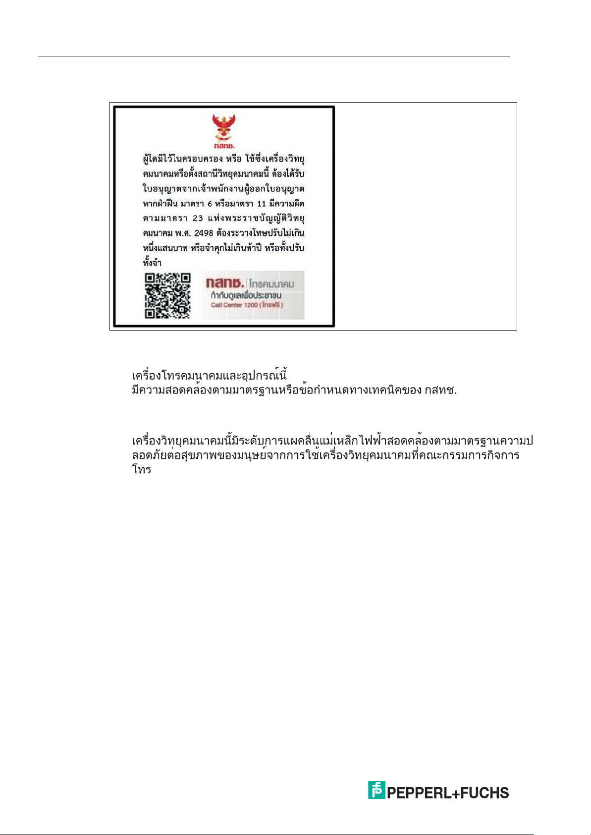
2.5 Approval Thailand
Device type: IUH-F190-V1-FR2-12
Part number: 309845
1.
(This telecommunication equipment conforms to the standard or technical requirements of
NBTC.)
2.
(This radiocommunication equipment has the electromagnetic field strength in compliance
with the Safety Standard for the Use of Radiocommunication Equipment on Human Health
announced by the National Telecommunications Commission.)
2.6 Additional country-specific approvals
For all current approvals see the data sheet of your read / write head under www.pepperlfuchs.com.
10
2020-03
IUH-F190-V1-*, IUT-F190-R4-V1*
Frequency
[MhZ]
125 kHz
2,45 GHz
13,56 MHz
5,8 GHz
868/915 MHz
0,1
LF
1 10
HF
100 1000
UHF
10000
MW
Product Description
3 Product Description
3.1 RFID Frequency Bands
The following diagram shows the position of the different frequency bands used for RFID. The
read/write heads described in this manual operate in the frequency range from 865 MHz ...
868 MHz and from 902 MHz ... 928 MHz, highlighted in color.
• 100 kHz ... 135 kHz: Low frequency LF
• 13.56 MHz: High frequency HF
• 865 MHz ... 868 MHz (Europe), 902 MHz ... 928 MHz (USA), 920 MHz ... 925 MHz
(China): ultra-high frequency UHF
• 2.45 GHz and 5.8 GHz: Microwave MW
3.2 UHF general
3.2.1 Advantages of UHF
•
Long detection range
• UHF tags are available as cheap and space-saving adhesive labels
• High transfer rates
• Tag is available with a large working memory (user memory)
• Bulk detection
3.2.2 Applications for UHF systems
•
Identification in galvanic coating or painting systems used in automotive production,
• Identification feasible over greater distances than with LF and HF systems,
• Identification of automotive superstructures in automotive production,
• Pallet identification and measurement of goods movements in the logistics sector, and
• Access control at unloading stations with HGV identification.
2020-03
11
IUH-F190-V1-*, IUT-F190-R4-V1*
USER
TID
UII/EPC
RESERVED
RFU [7:0]
10
h
1F
h
.
.
.
MSB LSB
DSFID [7:0]
00
h
0F
h
TID [15:0]
10
h
1F
h
.
.
.
MSB LSB
TID [31:16]
00
h
0F
h
UII/EPC [N:N-15]
20
h
210
h
2F
h
.
.
.
MSB LSB
PC [15:0]
10
h
1F
h
UII/EPC [15:0]
CRC-16 [15:0]
00
h
0F
h
Access Password [15:0]
30
h
3F
h
.
.
.
MSB LSB
Access Password [31:16]
20
h
2F
h
Kill Password [15:0]
10
h
1F
h
Kill Password [31:16]
00
h
0F
h
Bank 11
Bank 10
Bank 01
Bank 00
SR/ER
SW/EW
SS/ES
SP
SF/EF
.
.
.
Optional XPC_W2 [15:0]
Optional XPC_W2 [15:0]
.
.
.
220
h
21F
h
22F
h
Memory module
Commands
Read / write head
Product Description
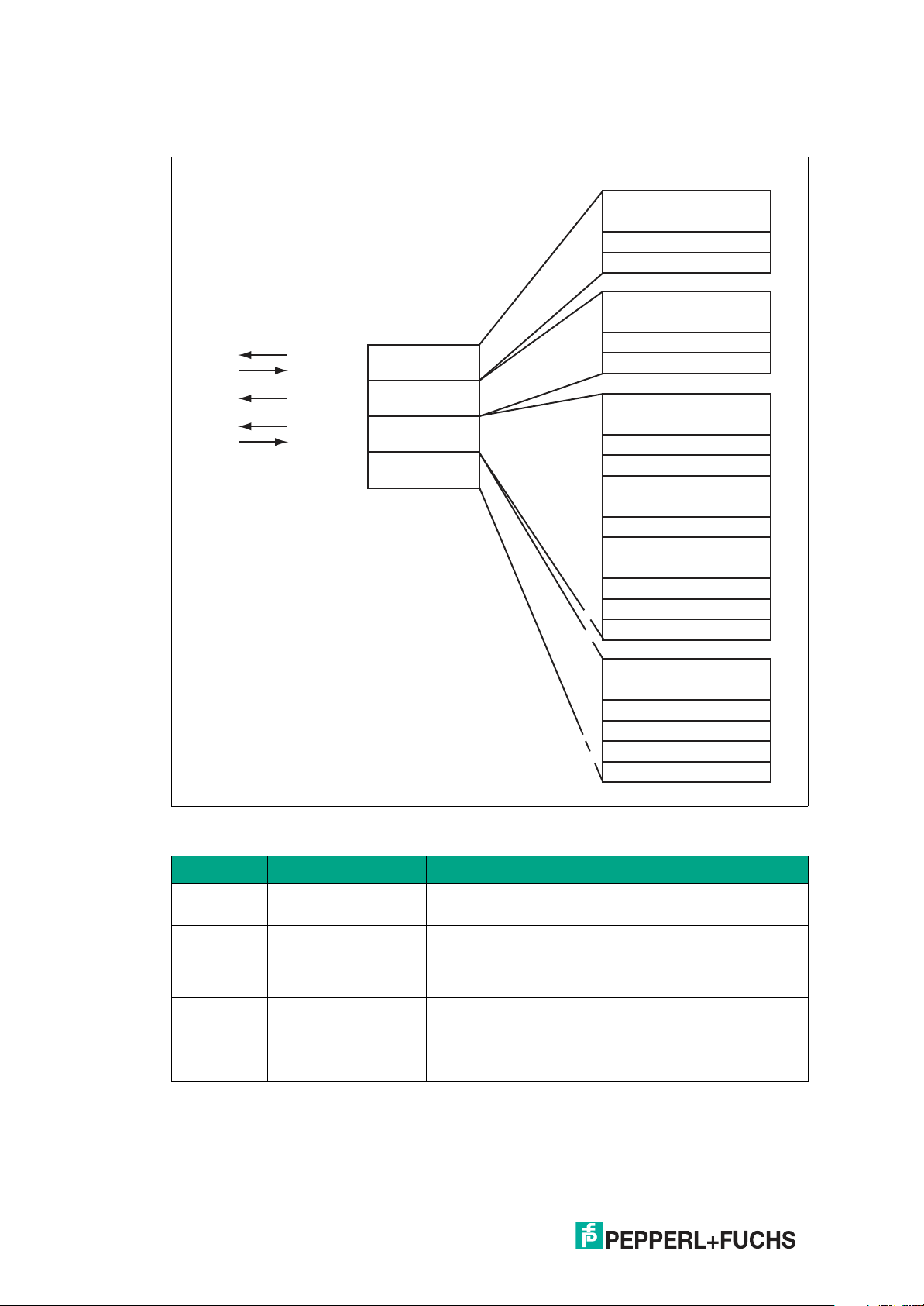
3.2.3 Memory Structure of a Tag in Accordance with EPC Gen 2 (ISO/IEC 18000-63)
12
The memory module of an EPC Gen 2 (ISO/IEC 18000-63) tag is split into four segments. The
main contents of these segments are:
Segment Function Length
Bank 00
(00
Bank 01
(01
Bank 10
(10
Bank 11
(11
= 0
dec
)
bin
= 1
dec
)
bin
= 2
= 3
dec
dec
)
)
bin
bin
Password management
Unique Item Identifier
(UII)
Electronic Product
Code (EPC)
Tag ID (TID) 4 bytes (MDID, TMN) + 0, 4, or 8 bytes
User memory Depending on the tag type, /column "User Data"
Depending on the tag type, /column "Bank 00"
Depending on the tag type, /column "UII/EPC"
2020-03

IUH-F190-V1-*, IUT-F190-R4-V1*
Product Description
Bank 00: Password Management
The segment Bank 00 contains the password management information, comprising the
access password and the kill password. The read/write head manages the kill password with
the standard read/write commands SW and SR. The access password is not supported. See
"Single Read Words SR" on page 43, see "Single Write Words SW" on page 44, and see
"Memory Module for Tag Accesses to the "Memory Bank" MB" on page 52.
Bank 01: UII/EPC
In addition to the Unique Item Identifier (UII), the segment Bank 01 contains a calculated
checksum CRC (Cyclic Redundancy Check) for verifying data on the tag and the protocol control (PC) area. The PC area contains:
• The length of the UII
• The Application Family Identifier (AFI) box
• A bit switch that shows whether the UII contains an EPC sequence of numbers in accor-
dance with ISO (see chapter 3.2.4)
• A bit switch that shows whether data is stored in segment bank 11 (if present)
The data is addressed via the following commands: single read special read-only code (SS),
single write special read-only code (SP), and enhanced read special read-only code (ES). See
"Single Read Special Read-Only Code SS" on page 42, see "Single Write Special Read-
Only Code SP" on page 42, and see "Enhanced Read Special Read-Only Code ES" on
page 42.
Bank 10: TID
The segment Bank 10 contains the tag identifier (TID), consisting of the part number and
optional serial number of the tag. This data is permanently stored without being changed. The
first byte denotes the class of the tag with E0
on the class, and can be derived from standard ISO/IEC 18000-63.
Example:
All tags with the class EPC Gen 2 (ISO/IEC 18000-63) are marked with E2
prised as follows:
• 4 bytes: part number of the tag
• 1 byte: identifier
• 12 bits: tag mask designer identifier (MDID)
• 12 bits: tag model number (TMN), defined by the manufacturer:
• 4 or 8 bytes: serial number of the tag
Depending on the manufacturer, the serial numbers do not have to be unique or may even
be omitted.
The data in segment Bank 10 can be output via the single read read-only code (SF) and
enhanced read read-only code (EF) commands. (see "Single Read Read-Only Code SF" on
page 41 and see "Enhanced Read Read-Only Code EF" on page 41)
hex
, E2
hex
, or E3
. The rest of the TID depends
hex
. The TID is com-
hex
Bank 11: User Memory
Segment Bank 11 contains an area to which the user has free access. This size of this area
depends on the chip type, or the area may not be present.
The data in segment Bank 11 is addressed via the single read words (SR), single write words
(SW), enhanced read words (ER), and enhanced write words (EW) commands. (see "Single
Read Words SR" on page 43, see "Single Write Words SW" on page 44, see "Enhanced
Read Words ER" on page 44, and see "Enhanced Write Words EW" on page 44)
2020-03
13

IUH-F190-V1-*, IUT-F190-R4-V1*
8 Bit 3 Bit 3 Bit 20 - 40 Bit 4 - 24 Bit 38 Bit
5
dez
0
dez
48
dez
4050143
dez
203886
dez
124
dez
Header
Filter value
Partition
Company Prefix
Object class Serial number
Length
Value
Product Description
3.2.4 Elektronic Product Code (EPC)
The electronic product code is a unique identifier in the form of a sequence of numbers. The
number sequence has a set structure and a length of 64 bits, 80 bits, 96 bits, or longer
(depending on the EPC Ident number used). This number sequence is saved to the RFID tag,
offering worldwide unique identification of the tagged object.
The system of Electronic Product Codes (EPC) was defined by GS1/EPCglobal for use in
inventory management. Tags with memory banks for EPC codes must be programmed by the
user. The memory of new tags must not contain any valid EPC codes. The EPC numbers are
managed and assigned by GS1. To obtain EPC numbers, please contact the GS1 branch in
your country (http://www.gs1.com/contact).
The electronic product code is defined by EPCglobal with at present 13 different encoding
schemes. SGTIN-96 (serialized global trade item number) is given here as an example of a frequently used encoding scheme. SGTIN-96 has a defined format, and is structured as follows:
1. Header: The header specifies the EPC standard used, and denotes the number se-
quence.
2. Filter value: Denotes the unit of the product, for example, end product, additional pack-
aging, pallet.
3. Partition: Denotes the point at which the following company prefix ends and the object
data begins.
4. Company Prefix: Assigned sequence of numbers that identifies the producer.
5. Object class: Sequence of numbers that describes the object, e.g., item number.
The company prefix and the object class are each of variable length, but together are always 44 bits long.
6. Serial number: Sequence of numbers that identifies the item, e.g., the sequential serial
number of the item.
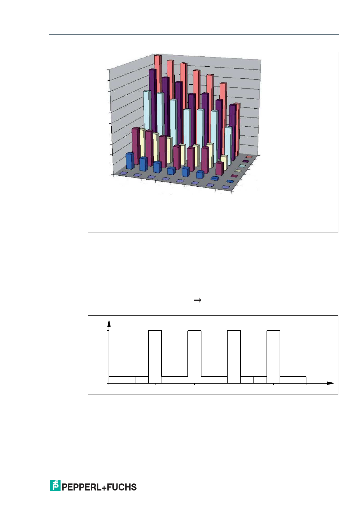
3.2.5 Influence of various materials on the sensing range
In the UHF range, the nature of the surrounding area and the surface to which the transponder
is secured have a serious influence on the range that the system can attain. The UHF transponder cannot be mounted on metal without requiring adaptations. Glass has a negative influence
on the sensing range when used as a mounting surface. If a UHF transponder is mounted on
damp material, the sensing range is much poorer than the range of a transponder mounted on
dry material. The mounting surface often affects the read range much more than the material
between the transponder and the read/write head. The graph shows the effect of different
materials on the sensing range.
14
2020-03
IUH-F190-V1-*, IUT-F190-R4-V1*
0 %
10 %
20 %
30 %
40 %
50 %
60 %
70 %
80 %
90 %
100 %
Material
underground
Material between transponder and
read / write head
Foam material
Film
Cardboard (dry)
Cardboard (wet)
Wood (dry)
Glass
Metal
A
i
r
F
i
l
m
C
a
r
d
b
o
a
r
d
(
d
r
y
)
C
a
r
d
b
o
a
r
d
(
w
e
t
)
W
o
o
d
(
d
r
y
)
F
o
am
m
a
t
e
r
i
a
l
G
l
a
s
s
M
e
t
a
l
W
erp
2.0
865.0 868.0865.7 867.5 MHz
1 2 3 4 5 6 7 8 9 10 11 12 13 14 15 Channel
866.9866.3
Product Description
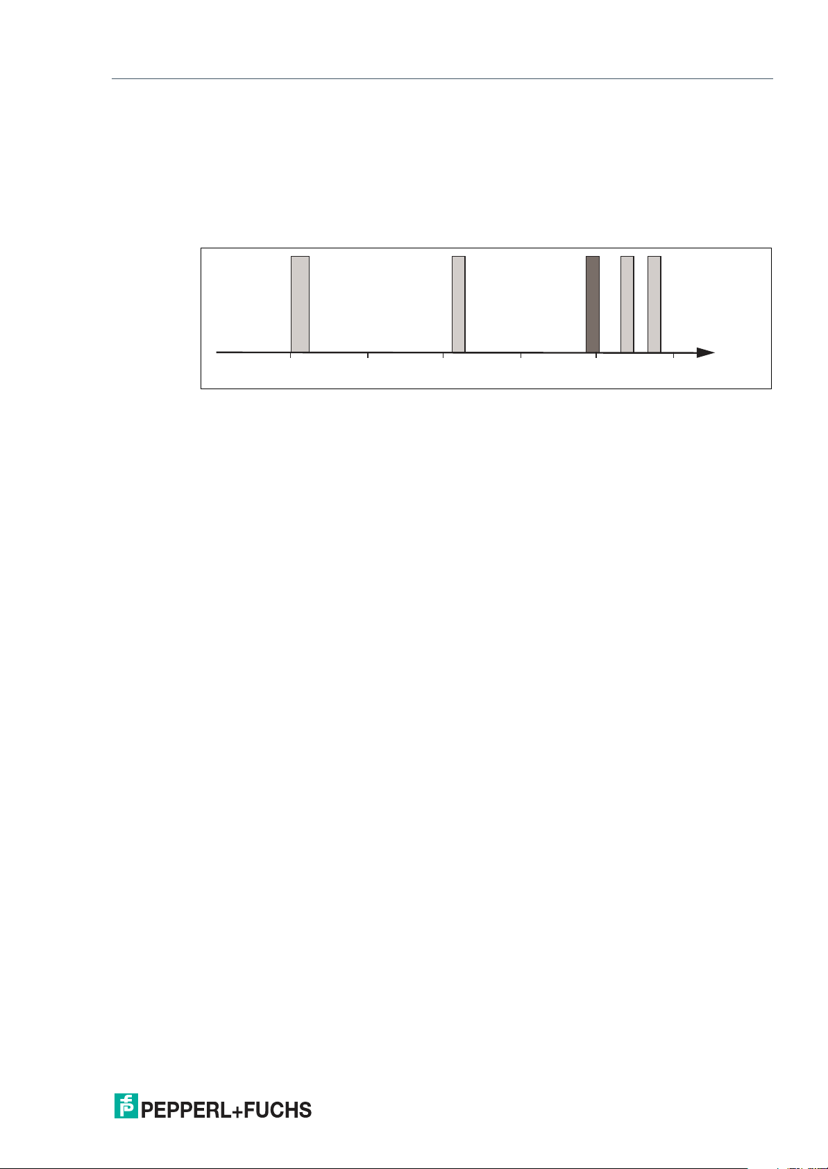
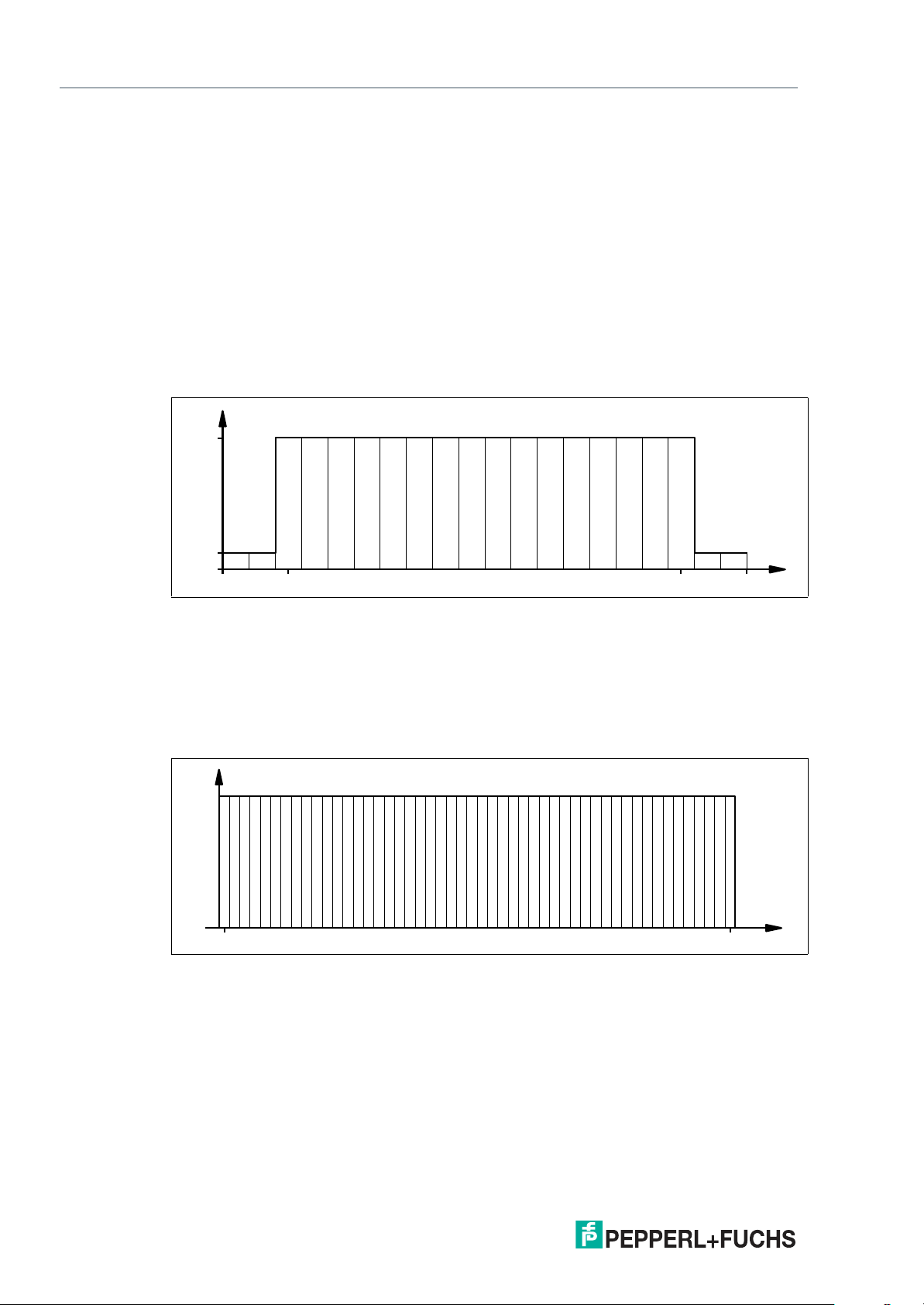
3.2.6 Dense Reader Mode (DRM)
Europe
A special operating mode for read/write tags in accordance with the specification EPC Gen 2
(ISO/IEC 18000-63) allows several read/write heads to be operated close to each other simultaneously without interference.
In accordance with EN 302208, the read/write head uses only channels 4, 7, 10, and 13 in this
mode for transmission (read/write head read/write tag communication path). The transmission power is a maximum of 2 W
2020-03
Figure 3.1
The response from the read/write tag appears via the frequency offset, which is achieved by
the modulation used in this mode on the two adjacent channels. Due to the high level difference between the transmission channels and the response channels, this technology offers
major benefits for reusing frequencies.
in accordance with EN 302208.
ERP
15
IUH-F190-V1-*, IUT-F190-R4-V1*
Channel
0.1
2.0
920 925920.625 924.375 MHz
W
erp
0 1 2 3 4 5 6 7 8 9 10 11 12 13 14 15 16 17 18 19
0.2
4.0
902.75 927.25MHz
Channel
W
eirp
10 15 2051 30 35 4025 45 50
Product Description
3.2.7 Frequency Hopping Spread Spectrum
With FHSS (Frequency Hopping Spread Spectrum), the information to be transmitted is distributed successively through multiple channels. Only one frequency channel is used at any one
time. This results in a larger bandwidth for the entire signal, in spite of the fact that each channel has a smaller bandwidth. In this section the channel assignment for China and the USA is
shown graphically. For both assignments, different parameters apply, such as channel number
and channel bandwidth. Different parameterizations apply in other countries.
3.2.7.1 China
In China, the frequency range 920 MHz ... 925 MHz is available for UHF-RFID read/write
heads. The range is split into channels, each with a bandwidth of 250 kHz. A maximum of 2
W
is permitted on 16 of the available channels. The transmission power is indicated in
ERP
W
. FHSS is used with a maximum retention time of two seconds. The UHF RFID read/write
ERP
head for China uses channel 2 to 17.
Figure 3.2
3.2.7.2 United States
The ISM band from 902 MHz ... 928 MHz is available in the USA. The band is split into 50
channels, each with a 500 kHz bandwidth. FHSS with a maximum retention time of 0.4 seconds is used. All channels must be used. Channel restriction is not permitted.
In contrast to the read/write heads for Europe and China, the transmission power is indicated in
W
. A maximum of 4 W
eirp
Figure 3.3
is permitted on all channels.
eirp
3.2.8 Relevant Standards for UHF
European radio standards: EN 300220 and EN 302208
Usage recommendations for RFID type labels, information about recycling, installation of readers and antennae: ISO/IEC TR 24729 parts 1-4
Installation and commissioning of UHF-RFID systems: ETSI TR 102436
Description of air interface: EPC Gen 2 (ISO/IEC 18000-63)
16
2020-03

IUH-F190-V1-*, IUT-F190-R4-V1*
Product Description
3.3 Countries of Use
Note
Transmission License
A country-specific transmission license is required to operate the read/write head. In the
European Union, the manufacturer's declaration of conformity constitutes an adequate license.
All currently valid transmission licenses can be found in the datasheet for the respective
read/write head at www.pepperl-fuchs.com.
Note
Country Identifier
All read/write heads operate within their maximum frequency range with the appropriate
settings for the relevant country. The country-specific settings are configured during production
and cannot be subsequently modified.
Note
If you wish to use the read/write head in a country not included in this chapter, make sure the
relevant values for the read/write head are consistent with the local conditions before use.
The frequency access procedure used is part of the country-specific settings.
Frequency Access Method
• In many countries, including the USA and China, a frequency hopping spread spectrum is
used. See chapter 3.2.7. The number and position of the frequencies is fixed and cannot
be changed by the user. All channels are used.
• A programmable frequency list is used in other countries, including the European Union,
Singapore, Vietnam, and India. You can compile this frequency list from a specified set of
channels. Four channels are specified in the European Union as appropriate for dense
reader mode in accordance with EN 302208. See chapter 3.2.6. With this setting, you can
configure one, multiple, or all four channels.
3.3.1 European Union
In the European Union, the use of RFID in the UHF range is regulated by EN 302208.
• UHF frequency range: 865 MHz … 868 MHz
• Radiated power: 3 mW … 1000 W
• Channel bandwidth: 200 kHz
• Channel spacing: 600 kHz
• Frequency access method: programmable frequency list
• Number of predefined channels: 4
Programmable channels: 4, 7, 10, 13
Center frequencies: 865.7 MHz, 866.3 MHz, 866.9 MHz, 867.5 MHz
Up to 4 channels can be parameterized and used in sequence.
Default: dense reader mode with channel 4, 10, 7, 13. See chapter 3.2.6.
; Default = 50 mW
ERP
ERP
3.3.2 Argentina
The regulations for the UHF frequency range in Argentina are the same as the regulations for
the UHF frequency range in the USA. See chapter 3.3.20.
2020-03
17

IUH-F190-V1-*, IUT-F190-R4-V1*
Product Description
3.3.3 Australia
In Australia, the use of RFID in the UHF range is regulated as follows:
• UHF frequency range: 920 MHz ... 926 MHz
• Radiated Power: 3 … 1000 mW
• Channel bandwidth: 500 kHz
• Channel spacing: 500 kHz
• Frequency access method: frequency hopping spread spectrum. See chapter 3.2.7.
• Number of channels: 12
Channels used: 1, 2, 3, ... 12
Center frequencies: 919.75 MHz + (M x 0.5) MHz
All 12 channels are always used.
3.3.4 Brazil
In Brazil, the use of RFID in the UHF range is regulated as follows:
• UHF frequency range: 915 MHz … 928 MHz
• Radiated Power: 3 … 1250 mW
• Channel bandwidth: 250 kHz
• Channel spacing: 250 kHz
• Frequency access method: frequency hopping spread spectrum. See chapter 3.2.7.
• Number of channels: 52
Channels used: 1, 2, 3, ... 52
; Default = 125 mW
EIRP
; Default = 125 mW
EIRP
EIRP
EIRP
Center frequencies: 914.875 MHz + (M x 0.25) MHz
All 52 channels are always used.
3.3.5 Canada
The regulations for the UHF frequency range in Canada meet the requirements for the UHF frequency range in the U.S.. See chapter 3.3.20.
3.3.6 China
In China, the use of RFID in the UHF range is regulated by the provisions of the China Ministry
of Industry and Information Technology (CMIIT).
• UHF frequency range: 920 MHz ... 925 MHz
• Radiated Power: 3 … 800 mW
• Channel bandwidth: 250 kHz
• Channel spacing: 250 kHz
• Frequency access method: frequency hopping spread spectrum (China). See chapter
3.2.7.
• Number of channels: 16
Channels used: 2, 3, 4, ... 17
Center frequencies: 920.125 MHz + (M x 0.25) MHz
; Default = 80 mW
ERP
ERP
18
All 16 channels are always used.
2020-03

IUH-F190-V1-*, IUT-F190-R4-V1*
Product Description
3.3.7 Hong Kong
The regulations for the UHF frequency range of 865 MHz to 868 MHz in Hong Kong are the
same as the regulations for the UHF frequency range in the European Union. See chapter
3.3.1.
The regulations for the UHF frequency range of 920 MHz to 925 MHz in Hong Kong are the
same as the regulations for the UHF frequency range in Thailand. See chapter 3.3.19.
3.3.8 India
In India, the use of RFID in the UHF range is regulated in accordance with EN 302208.
• UHF frequency range: 865 MHz … 867 MHz
• Radiated Power: 3 … 800 mW
• Channel bandwidth: 200 kHz
• Channel spacing: 200 kHz
• Frequency access method: programmable frequency list
• Number of predefined channels: 10
Programmable channels: 1, 2, 3, ... 10
Center frequencies: 865.1 MHz, 865.3 MHz, 865.5 MHz, 865.7 MHz, 865.9 MHz,
866.1 MHz, 866.3 MHz, 866.5 MHz, 866.7 MHz, 866.9 MHz
Up to four channels can be parameterized simultaneously and used in sequence.
Default: dense reader mode on channel 1, 7, 4, 10. See chapter 3.2.6.
3.3.9 Indonesia
In Indonesia, the use of RFID in the UHF range is regulated as follows:
• UHF frequency range: 920 MHz … 923 MHz
• Radiated Power: 3 … 400 mW
• Channel bandwidth: 500 kHz
• Channel spacing: 500 kHz
• Frequency access method: frequency hopping spread spectrum. See chapter 3.2.7.
; Default = 50 mW
ERP
; Default = 125 mW
eirp
ERP
eirp
• Number of channels: 6
Channels used:1, 3, 5, 2, 4, 6
Center frequencies: 919.75 MHz + (M x 0.5) MHz
All 6 channels are always used.
2020-03
19

IUH-F190-V1-*, IUT-F190-R4-V1*
Product Description
3.3.10 Japan
In Japan, the use of RFID in the UHF range is regulated as follows:
• UHF frequency range: 916.7 MHz … 920.5 MHz
• Radiated Power: 3 … 125 mW
• Channel bandwidth: 200 kHz
• Channel spacing: 1200 kHz
• Frequency access method: programmable frequency list.
• Number of predefined channels: 4
Programmable channels: 5, 11, 17, 23
Center frequencies: 916.8 MHz, 918.0 MHz, 919.2 MHz, 920.4 MHz
Up to four channels can be parameterized and used in sequence.
Default: dense reader mode on channel 5, 17, 11, 23. See chapter 3.2.6.
3.3.11 Colombia
The regulations for the UHF frequency range in Colombia are the same as the regulations for
the UHF frequency range in the USA. See chapter 3.3.20.
3.3.12 Malaysia
In Malaysia, the use of RFID in the UHF range is regulated as follows:
• UHF frequency range: 919 MHz … 923 MHz
• Radiated Power: 3 … 800 mW
• Channel bandwidth: 500 kHz
• Channel spacing: 500 kHz
; Default = 125 mW
EIRP
; Default = 80 mW
ERP
EIRP
ERP
• Frequency access method: frequency hopping spread spectrum. See chapter 3.2.7.
• Number of channels: 8
Channels used: 1, 2, 3, ... 8
Center frequencies: 918.75 MHz + (M x 0.5) MHz
All 8 channels are always used.
3.3.13 Morocco
In Morocco, the use of RFID in the UHF range is regulated in accordance with EN 302208:
• UHF frequency range: 867,6 … 868 MHz
• Radiated Power: 3 … 500 mW
• Channel bandwidth: 200 kHz
• Channel spacing: 200 kHz
• Frequency access method: programmable frequency list.
• Number of predefined channels: 2
Programmable channels: 1, 2
Center frequencies: 867.7 MHz, 867.9 MHz
Up to two channels can be parameterized simultaneously and used in sequence.
Default: dense reader mode on channel 1, 2. See chapter 3.2.6.
; Default = 50 mW
ERP
ERP
2020-03
20

IUH-F190-V1-*, IUT-F190-R4-V1*
Product Description
3.3.14 Mexico
The regulations for the UHF frequency range in Mexico meet the requirements for the UHF frequency range in the U.S.. See chapter 3.3.20.
3.3.15 New Zealand
In New Zealand, the use of RFID in the UHF range is regulated as follows:
• UHF frequency range: 921.5 MHz … 928 MHz
• Radiated Power: 3 … 1250 mW
• Channel bandwidth: 500 kHz
• Channel spacing: 500 kHz
• Frequency access method: frequency hopping spread spectrum. See chapter 3.2.7.
• Number of channels: 13
Channels used: 1, 2, 3, ... 13
Center frequencies: 921.25 MHz + (M x 0.5) MHz
All 13 channels are always used.
3.3.16 Russia
In Russia, the use of RFID in the UHF range is regulated in accordance with EN 302208:
• UHF frequency range: 866 MHz … 867.6 MHz
• Radiated Power: 3 … 800 mW
• Channel bandwidth: 200 kHz
• Channel spacing: 200 kHz
• Frequency access method: programmable frequency list.
• Number of predefined channels: 8
Programmable channels: 1, 2, 3, ... 8
; Default = 125 mW
EIRP
; Default = 50 mW
ERP
EIRP
ERP
Center frequencies: 866.1 MHz, 866.3 MHz, 866.5 MHz, 866.7 MHz, 866.9 MHz,
867.1 MHz, 867.3 MHz, 867.5 MHz
Up to four channels can be parameterized simultaneously and used in sequence.
Default: dense reader mode on channel 1, 7, 4. See chapter 3.2.6.
2020-03
21
 Loading...