

Pepperl+Fuchs IUH-F117-V1-EU, IUH-F117-V1-US, IUH-F117-V1-CN User Manual
MANUAL
IUH-F117-V1-EU
IUH-F117-V1-US
IUH-F117-V1-CN
FACTORY AUTOMATION
R/W head for IDENTControl

IUH-F117-V1-*
With regard to the supply of products , the current issue of the following document is applicable: The
General Terms of Delivery for Products and Services of the Electrical Industry, published by the
Central Association of the Electrical Industry (Zentralverband Elektrotechnik und Elektroindustrie
(ZVEI) e.V.) in its most recent version as well as the supplementary clause: "Expanded reservation
of proprietorship"

IUH-F117-V1-*
Contents
1 Introduction......................................................................... 5
2 Declaration of Conformity ................................................. 6
3 Safety................................................................................... 7
3.1 Symbols relevant to safety ............................................................................ 7
3.2 Intended Use ................................................................................................7
3.3 General notes on safety................................................................................. 8
4 Product Description ........................................................... 9
4.1 UHF general .................................................................................................9
4.1.1 Advantages of UHF .................................................................................. 9
4.1.2 Permissible Operating Capacity of UHF ...................................................9
4.1.3 Permissible Frequency Range of UHF...................................................... 9
4.1.4 Applications for UHF systems...................................................................9
4.1.5 Memory Structure of a Tag in Accordance with ISO 18000-6C/
EPC Class 1 Gen 2 .................................................................................10
4.1.6 Electronic product code EPC .................................................................11
4.1.7 Unique numbering as per ISO ................................................................12
4.1.8 Influence of various materials on the sensing range ...............................13
4.1.9 Countries of Use.....................................................................................14
4.1.10 Dense Reader Mode DRM ..................................................................... 14
4.1.11 Europe....................................................................................................15
4.1.12 China......................................................................................................15
4.1.13 USA........................................................................................................16
4.1.14 RFID Frequency Bands ..........................................................................16
4.1.15 Relevant UHF standards ........................................................................16
4.2 General Functions and Features..................................................................17
4.3 Indicators and Controls ...............................................................................17
4.4 Connection .................................................................................................18
4.5 Scope of Delivery........................................................................................18
4.6 Accessories ................................................................................................18
4.6.1 IDENTControl .........................................................................................18
4.6.2 Read/Write Tags .....................................................................................19
4.6.3 Connection cable for R/W heads and trigger sensors ............................19
4.6.4 Cable connectors for the power supply ..................................................20
4.6.5 Installation accessories ..........................................................................20
2012-09
3

IUH-F117-V1-*
Contents
5 Installation ........................................................................ 21
5.1 Storage and transport ................................................................................. 21
5.2 Unpacking .................................................................................................. 21
5.3 Mounting .................................................................................................... 21
5.3.1 Orientation in the room .......................................................................... 22
5.3.2 Minimum and Maximum Distances........................................................ 22
5.3.3 Polarization ............................................................................................ 23
5.4 Connection................................................................................................. 24
5.5 EMC concept ............................................................................................. 24
6 Commissioning ................................................................ 26
6.1 Connection................................................................................................. 26
6.2 Device settings ........................................................................................... 26
6.3 Operating via the Command Interface ........................................................ 26
7 Operation .......................................................................... 31
7.1 General ....................................................................................................... 31
7.2 Read/Write Commands .............................................................................. 31
7.3 Configuration commands ........................................................................... 34
7.3.1 ChangeTag Command........................................................................... 34
7.3.2 ReadParam/WriteParam Commands ..................................................... 35
7.3.3 ParamTyp............................................................................................... 36
7.4 Legend ....................................................................................................... 40
7.5 Fault/status messages ................................................................................ 41
8 Service and Maintenance................................................ 42
9 Troubleshooting ............................................................... 43
10 ASCII table ........................................................................ 44
11 Appendix........................................................................... 45
11.1 Dimensions ................................................................................................ 45
11.2 Technical Data............................................................................................ 45
11.3 Detection Range ........................................................................................ 46
4
2012-09

IUH-F117-V1-*
Introduction
1Introduction
Congratulations
You have chosen a device manufactured by Pepperl+Fuchs. Pepperl+Fuchs
develops, produces and distributes electronic sensors and interface modules for
the market of automation technology on a worldwide scale.
Before you install this device and put it into operation, please read the operating
instructions thoroughly. The instructions and notes contained in this operating
manual will guide you step-by-step through the installation and commissioning
procedures to ensure trouble-free use of this product. By doing so, you:
■ guarantee safe operation of the device
■ can utilize the entire range of device functions
■ avoid faulty operation and the associated errors
■ reduce costs from downtimes and incidental repairs
■ increase the effectiveness and operating efficiency of your plant.
Store this operating manual somewhere safe in order to have it available for future
work on the device.
After opening the packaging, please ensure that the device is intact and that the
package is complete.
Symbols used
The following symbols are used in this manual:
Note!
This symbol draws your attention to important information.
Handling instructions
You will find handling instructions beside this symbol
Contact
If you have any questions abou t the device, its functions, or accessories, please
contact us at:
Pepperl+Fuchs GmbH
Lilienthalstraße 200
68307 Mannheim
Telephone: +49 621 776-4411
Fax: +49 621 776-274411
E-Mail: fa-info@pepperl-fuchs.com
2012-09
5

IUH-F117-V1-*
ISO9001
Declaration of Conformity
2 Declaration of Conformity
All products were developed and manufactured under observance of the
applicable European standards and guidelines.
Note!
A Declaration of Conformity can be requested from the manufacturer.
The product manufacturer, Pepperl+Fuchs GmbH, 68307 Mannheim, has a
certified quality assurance system that conforms to ISO 9001.
FCC ID: IREIUH-F117-V1
This device complies with Part 15 of the FCC Rules. Operation is subject to the following
two conditions:
1. this device may not cause harmful in terference, and
2. this d evice must accept any interference received, including inte rference that may cause
undesired operation.
Notice:
Changes or modifications made to this equipment not expressly approved by
Pepperl+Fuchs GmbH may void the FCC authorization to operate this equipment.
6
NOTE:
This equipment has been tested and found to comply with the limits for a Class A
digital device, pursuant to part 15 of the FCC Rules. These limits are designed to
provide reasonable protection against harmful interference when the equipment is
operated in a commercial environment. This equipment generates, uses, and can
radiate radio frequency energy and, if not installed and used in accordance with
the instruction manual, may cause harmful interference to radio communications.
Operation of this equipment in a residential area is likely to cause harmful
interference in which case the user will be required to correct the interference at
his own expense.
2012-09

IUH-F117-V1-*
Safety
3Safety
3.1 Symbols relevant to safety
Danger!
This symbol indicates a warning about an immediate possible danger.
In case of ignoring the consequences may range from personal injury to death.
Warn ing!
This symbol indicates a warning about a possible fault or danger.
In case of ignoring the consequences may cause personal injury or heaviest
property damage.
Caution!
This symbol indicates a warning about a possible fault.
In case of ignoring the devices and any connected facilities or systems may be
interrupted or fail completely.
3.2 Intended Use
The IUH-F117-V1-* is a read/write head for passive code and read/write tags.
The IUH-F117-V1-* operates at a frequency in the UHF range (Europe:
865–868 MHz, USA: 902–928 MHz, China: 920–925 MHz).
Always operate the device as described in these instructions to ensure that the
device and connected systems function correctly. The protection of operating
personnel and plant is only guaranteed if the device is operated in accordance
with its intended use.
Read through these instructions thoroughly. Familiarize yourself with the device
before installing, mounting, or operating.
Pepperl+Fuchs GmbH provides no guarantee that the information contained in
this document does not contain third party industrial property rights.
Pepperl+Fuchs GmbH does not issue any licenses to its own or third party patents
or other industrial property rights in this document.
Note!
The installation recommendations made in this document are based on favorable
basic conditions. Pepperl+Fuchs GmbH provides no guarantee of correct function
in environments belonging to other systems.
Warn ing!
Minimum distance
When installing the device in areas covered under US Code of Federal
Regulations Part 15 a minimum distance of 25 cm between antenna and the
2012-09
human body must be maintained.
7

IUH-F117-V1-*
Safety
War ning !
Malfunctions with pacemakers
This device does not exceed the permissible limits for electromagnetic fields.
Maintain a minimum distance of 25 cm between the device and your pacemaker.
Inadequate distance from the read/write head can result in inhibitions,
reprogramming or incorrect stimulation pulses.
3.3 General notes on safety
Only instructed specialist staff may operate the device in accordance with the
operating manual.
User modification and or repair are dangerous and will void the warranty and
exclude the manufacturer from any liability. If serious faults occur, stop using the
device. Secure the device against inadvertent operation. In the event of repairs,
return the device to your local Pepperl+Fuchs representative or sales office.
The connection of the device and maintenance work when live may only be
carried out by a qualified electrical specialist.
The operating company bears responsibility for observing locally applicable
safety regulations.
Store the not used device in the original packaging. This offers the device optimal
protection against impact and moisture.
Ensure that the ambient conditions comply with regulations.
Note!
Disposal
Electronic waste is hazardous waste. When disposing of the equipment, observe
the current statutory requirements in the respective country of use, as well as local
regulations.
2012-09
8

IUH-F117-V1-*
Product Description
4 Product Description
4.1 UHF general
4.1.1 Advantages of UHF
■ Large sensing range
■ UHF high-temperature transponder available for the automobile industry
■ UHF transponders are available as low-cost, space-saving adhesive labels
■ High transfer rates
■ Large quantities of data transferred, depending on the transponder
4.1.2 Permissible Operating Capacity of UHF
In Europe, a maximum of 2 W
302208-1) are permitted.
In the USA, a maximum of 4 W are
In China, a maximum of 2 W are
4.1.3 Permissible Frequency Range of UHF
The frequency range for UHF, in which the IUH-F117-V1-* read/write head
operates, is:
■ 865 MHz to 868 MHz in Europe in accordance with DIN EN 302208-1
■ 902 MHz to 928 MHz in the USA
■ 920 MHz to 925 MHz in China
4.1.4 Applications for UHF systems
■ Identification in galvanic coating or painting systems used in automotive
production,
■ Identification of vehicle bodies in final vehicle assembly,
■ Palette identification and tracking of goods in the logistics sector and
■ Truck identification for access control at loading stations.
(+33 dBm ERP in accordance with DIN EN
ERP
permitted.
EIRP
permitted.
ERP
2012-09
9
IUH-F117-V1-*
Product Description
4.1.5 Memory Structure of a Tag in Accordance with ISO 18000-6C/EPC Class 1 Gen 2
MSB LSB
10
h
00
h
MSB LSB
Commands
IUH-F117-V1-*
SR/ER
SW/EW
SF/EF
SS/ES
SP/EP
Bank 11
Bank 10
Bank 01
Bank 00
Memory module
USER
TID
UII/EPC
RESERVED
10
h
00
h
MSB LSB
Optional XPC_W2 [15:0]
220
h
Optional XPC_W2 [15:0]
210
h
20
h
10
h
00
h
MSB LSB
Access Password [15:0]
30
h
Access Password [31:16]
20
h
10
h
00
h
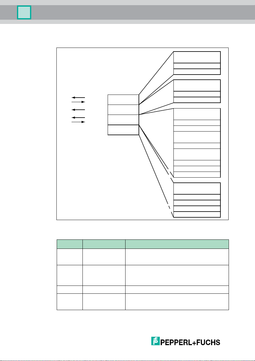
The memory module of an EPC-type Class 1 Gen 2 tag is split into 4 segments.
The essential contents of these segments are:
.
.
.
RFU [7:0]
DSFID [7:0]
.
.
.
TID [15:0]
TID [31:16]
.
.
.
.
.
.
UII/EPC [15:0]
.
.
.
UII/EPC [N:N-15]
PC [15:0]
CRC-16 [15:0]
.
.
.
Kill Password [15:0]
Kill Password [31:16]
1F
0F
1F
0F
22F
21F
2F
1F
0F
3F
2F
1F
0F
h
h
h
h
h
h
h
h
h
h
h
h
h
10
Segment Functi on Length
Bank 00 Password manager Depending on the tag type, see table "Tag Types
Bank 01 Unique Item
Identifier (UII)
Electronic Product
Code (EPC)
UHF 868 MHz" on page 35"Special read-only code"
column
Depending on the tag type, see table "Tag Types
UHF 868 MHz" on page 35"Special read-only code"
column
Bank 10 Ta g I D ( TI D) 8 byte
Bank 11 User data Depending on the tag type, see table "Tag Types
UHF 868 MHz" on page 35"Special read-only code"
column
2012-09

IUH-F117-V1-*
Product Description
Bank 00
The segment bank 00 contains the password manager, comprising the access
password and the kill password. This range is not currently supported by IUHF117-V1-*.
Bank 01
In addition to the UII, the segment bank 01 contains a calculated checksum CRC
(cyclic redundancy check) for verifying data on the tag and the protocol control
(PC) range. The PC range contains:
■ The length of the UII
■ The characteristic of the Application Family Identifier (AFI) field
■ A bit switch that shows whether the UII contains an EPC or MITL number
sequence in accordance with ISO (see chapter 4.1.6, see chapter 4.1.7&
see chapter 7.3)
■ A bit switch that shows whether data is stored in segment bank 11 (if
present)
All data in segment bank 01 are automatically set by IUH-F117-V1-*. The data is
addressed via the commands single read special read-only code (SS), single
write special read-only code (SP), enhanced read special read-only code (ES)
and enhanced write special read-only code (EP). (see "Single Read Special
Read-Only Code SS" on page 31, see "Single Write Special Read-Only Code SP"
on page 32, see "Enhanced Read Special Read-Only Code ES" on page 32& see
"Enhanced Write Special Read-Only Code EP" on page 32)
Bank 10
Segment bank 10 contains the part number and the serial number of the tag. This
data is permanently stored without being changed.
The data in segment bank 10 can be read out via the commands single read readonly code (SF) and enhanced read read-only code (EF). (see "Single read fixcode
SF" on page 31& see "Enhanced read fixcode (EF)" on page 31)
Bank 11
Segment bank 11 contains an area to which the user has free access. Depending
on chip type, this area has different sizes or is not present.
The data in segment bank 11 is addressed via the commands single read words
(SR), single write words (SW), enhanced read words (ER) and enhanced write
words (EW). (see "Single Read Words SR" on page 32, see "Single Write Words
SW" on page 33, see "Enhanced Read Words ER" on page 33& see "Enhanced
Write Words EW" on page 33)
4.1.6 Electronic product code EPC
The electronic product code is a unique code composed of a series of digits. This
series of digits has a defined structure and a length of 64 bits, 80 bits, 96 bit or
longer (depending on the EPC identification number used), is stored on the RFID
transponder and uniquely identifies every transponder all over the world.
2012-09
11
IUH-F117-V1-*
Header
Filter value
Partition EPC Manager Object class Serial number
Length
Val ue
1 = decimal
8 Bit 3 Bit 3 Bit 28 Bit 24 Bit 36 Bit
0011 1001 010 004 50123456 001234567 1234567891234
11 1 1
Product Description
GS1/EPCglobal developed the system of Electronic Product Codes (EPC) for use
in resource planning. Transponders with a memory for EPC codes are
programmed by the user. The memories of new transponders do not have to
contain valid EPC codes. The EPC numbers are allocated and managed by GS1.
If you require EPC numbers, please contact the respective GS1 branch in your
country (http://www.gs1.com/contact).
The electronic product code has a defined layout that is structured as follows:
1. Header: the header specifies the EPC standard used and contains the se-
ries of digits.
2. Filter value: describes the product unit, e.g., end product, packaging, prod-
uct range.
3. Partition: describes the point at which the EPC manager mentioned below
stops and the object data starts.
4. EPC Manager: allocated series of digits that identify the manufacturer.
5. Object class: series of digits that describe the object, e.g., article number.
6. Serial number: series of digits that identify the article, e.g., consecutive se-
rial numbers of the article.
To work with unique identifications without having to revert to potentially costly
EPC codes, we recommend using the UID and TID of the transponders
programmed permanently into the transponder chips by the semiconductor
manufacturer.
Note!
The TID on some transponder types is not unique. See table "Tag Types UHF 868
MHz" on page 35.
4.1.7 Unique numbering as per ISO
In addition to the Electronic Product Code (EPC), a series of MITL numbers can
also be used as a UII in accordance with ISO. MITL stands for Multi Industry
Tra n sp or t La be l.
Example:
25SLHUNIK15000905130035
The series consists of the following
1. Data identifier
25S describes a unique object.
2. Unique company ID
LH describes die issuing authority, in this example the European Health Industry Business Communications Council "EHIBCC."
12
2012-09
IUH-F117-V1-*
Product Description
UNIK describes the company, in this case "UNIK."
3. Serial number
15000905130035 is the unique serial number.
The relevant standards relating to unique identification include ISO/IEC 15434,
ISO/IEC 15459-1 to 8 and ISO/IEC TR 29162 (in preparation).
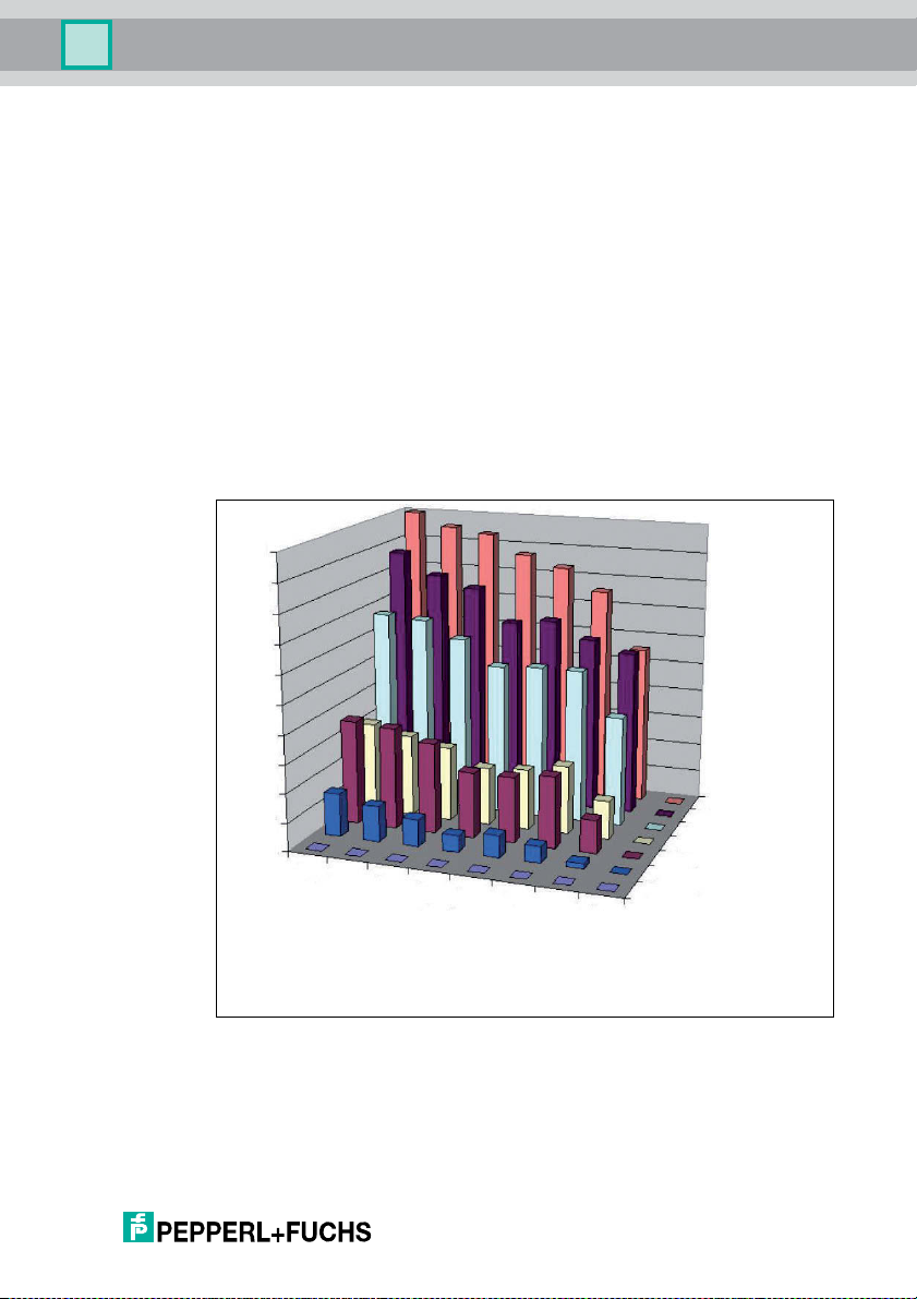
4.1.8 Influence of various materials on the sensing range
In the UHF range, the nature of the surrounding area and the surface to which the
transponder is secured have a serious influence on the range that the system can
attain. The UHF transponder cannot be mounted on metal without requiring
adaptations. Glass has a negative influence on the sensing range when used as a
mounting surface. If a UHF transponder is mounted on damp material, the
sensing range is much poorer than the range of a transponder mounted on dry
material. The mounting surface often affects the read range much more than the
material between the transponder and the read/write head. The graph shows the
effect of different materials on the sensing range.
100 %
90 %
80 %
70 %
60 %
50 %
40 %
30 %
20 %
10 %
0 %
r
Ai
Material between transponder and
read / write head
Film
Cardboard (dr
Cardboard (wet)
)
y
Wood (dr
)
y
Foam material
Glass
Metal
Cardboard (dry)
Cardboard (wet)
Wood (dry)
Glass
Metal
Foam material
Film
Material
underground
2012-09
13
IUH-F117-V1-*
W
erp
0.1
2.0
865.0 868.0865.6 867.4 MHz
0.5
123456789101112131415 Channel
866.8866.2
Product Description
4.1.9 Countries of Use
The IUH-F117-V1-* read/write head has transmission license in accordance with
DIN EN 302208-2.
Note!
If you wish to use a device in a country in which this standard is not effective,
make sure beforehand that the following values for the device are consistent with
the local conditions:
■ Frequency band
■ Pow er level
■ The described modulation and operating modes must be permitted
A list of countries of use can be found in "ERC Recommendation ERC/REC7003". These are available on the "European Communications Office ERO" website
under www.ero.dk as re commendation. The cu rren tly applicable countries of use
are listed in this document under Appendix 11.
4.1.10 Dense Reader Mode DRM
A special operating mode for read/write tags in accordance with the UHF Gen 2
specification allows several read/write heads to be operated next to each other
without interference.
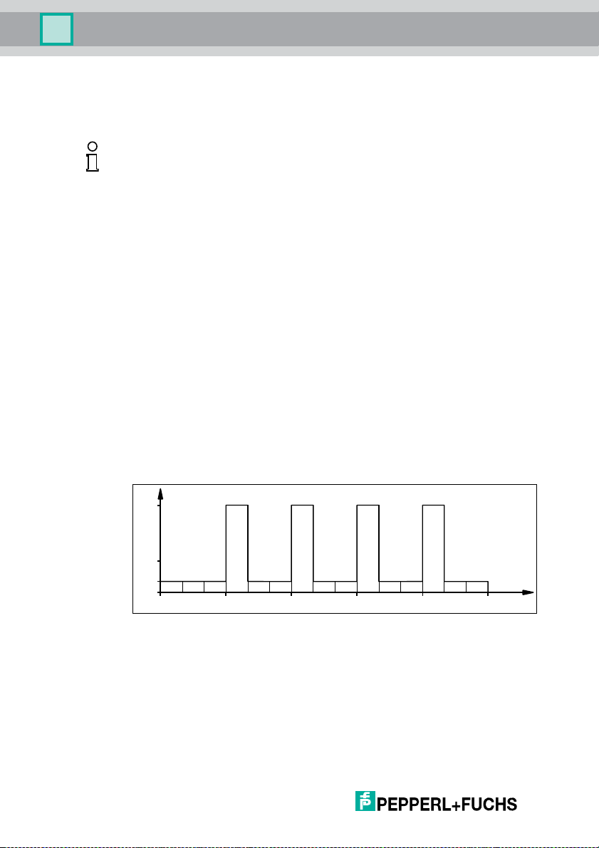
Europe
In line with EPC Global and ETSI EN 302208, only channels 4, 7, 10 and 13 are
used in this mode for transmission for the IUH-F117-V1-EU read/write head
(read/write head -> read/write tag communication path). The transmission power
is max. 2 W
erp
.
Figure 4.1
The read/write head can therefore only use preset channels. The response from
the read/write tag appears via the frequency offset, which is achieved by the
modulation used in this mode on the two adjacent channels. The IUH-F117-V1EU read/write head transmits on the four transmission channels 4, 7, 10 and 13,
provided that these channels have been preset. Due to the high level difference
between the transmission channels and the response channels, this technology
offers major benefits for reusing frequencies. This requires minimum distances
and therefore a minimum coupling between the antennas of adjacent read/write
heads to be maintained.
14
2012-09

IUH-F117-V1-*
0.1
2.0
865.0 868.0865.7 867.5 MHz
0.5
123456789101112131415 Channel
W
erp
Product Description
4.1.11 Europe
The IUH-F117-V1-EU read/write head has wireless approval to DIN EN 302208-2.
The read/write head is operated in dense reader mode (DRM). This operating
mode in accordance with the UHF Gen 2 specification allows several read/write
heads to be operated next to each other in the permitted channels (4, 7, 10 and
13) without interference.
Figure 4.2
4.1.12 China
In China, the frequency ranges 840–845 MHz and 920–925 MHz are availa ble for
UHF-RFID readers. This read/write head uses the 920–925 MHz range. The
range is split into 20 channels, each with a bandwidth of 250 kHz. On channels 0,
1, 18, and 19, only 100 mW
the spectrum. On channels 2–17, 2 W are
can be set. It is stated in W
used.
of transmission power are permitted at the edge of
erp
. FHSS with a maximum 2 seconds retention time is
erp
permitted. The transmission power
erp
W
erp
2.0
0.1
1 2 3 4 5 6 7 8 9 10111213141516171819
920 925920.625 924.125 MHz
Figure 4.3
2012-09
Channel
15
 Loading...