

Pepperl+Fuchs IPT FP, IPT1-FP Series Manual
MANUAL
IPT*-FP WITH U-P*-R4
Read/write station
with addressable
serial interface
FACTORY AUTOMATION

IPT*-FP WITH U-P*-R4
With regard to the supply of products, the current issue of the following document is applicable: The General Terms of Delivery for Products and Services of the Electrical Industry,
published by the Central Association of the Electrical Industry (Zentralverband Elektrotechnik und Elektroindustrie (ZVEI) e.V.) in its most recent version as well as the supplementary
clause: "Expanded reservation of proprietorship"

IPT*-FP WITH U-P*-R4
1 Introduction ................................................................. 5
2 Declaration of conformity........................................... 6
2.1 CE conformity............................................................................................6
3 Safety ........................................................................... 7
3.1 Symbols relevant to safety .......................................................................7
3.2 Intended use ..............................................................................................7
3.3 General safety instructions ......................................................................7
4 Product description .................................................... 8
4.1 Product family............................................................................................9
4.1.1 Code/data carrier.........................................................................................9
4.2 Range of application ...............................................................................10
4.3 Delivery package .....................................................................................10
4.4 Display and controls ...............................................................................11
4.5 Interfaces and connections .................................................................... 11
5 Installation ................................................................. 12
5.1 Storage and transport.............................................................................12
5.2 Unpacking ................................................................................................12
6 Commissioning ......................................................... 13
6.1 General information on commissioning................................................13
6.2 Commands...............................................................................................13
6.2.1 Command overview...................................................................................14
6.2.2 System commands....................................................................................16
6.2.3 Read/write commands...............................................................................19
6.2.4 IPC03 configuration commands ................................................................21
6.2.5 IPC03 password mode ..............................................................................25
6.2.6 Write fixcode ..............................................................................................26
6.2.7 Legend ......................................................................................................28
6.2.8 Status and error messages .......................................................................28
3

IPT*-FP WITH U-P*-R4
7 Technical specifications ...........................................29
7.1 Read/write station IPT*-FP ..................................................................... 29
7.2 Read/write distances IPT*-FP ................................................................ 30
7.3 Lower sections........................................................................................ 31
4

IPT*-FP WITH U-P*-R4
Introduction
1 Introduction
Congratulations
You have chosen a device manufactured by Pepperl+Fuchs. Pepperl+Fuchs develops,
produces and distributes electronic sensors and interface modules for the market of
automation technology on a worldwide scale.
Before you install this device and put it into operation, please read the operating instructions
thoroughly. The instructions and notes contained in this operating manual will guide you stepby-step through the installation and commissioning to ensure the trouble-free usage of this
product. This is useful to you, because with this you:
• support the safe operation of the device
• can utilize the device’s entire range of functions
• reduce faulty operation and the associated errors
• reduce costs from downtime and incidental repairs
• increase the effectiveness and operating efficiency of your plant.
Store this operating manual somewhere safe in order to have it available for future work on the
device.
Directly after opening the packaging, please ensure that the device is intact and that the
package is complete.
Symbols used
The following symbols are used in this manual:
Note!
This symbol draws your attention to important information.
Handling instructions
You will find handling instructions beside this symbol
Contact
If you have any questions about the device, its functions, or accessories, please contact us at:
Pepperl+Fuchs GmbH
Lilienthalstraße 200
68307 Mannheim
Telephone: +49 621 776-4411
Fax: +49 621 776-274411
098407 2009-04
E-Mail: fa-info@pepperl-fuchs.com
5

IPT*-FP WITH U-P*-R4
Declaration of conformity
2 Declaration of conformity
2.1 CE conformity
This product was developed and manufactured under observance of the applicable European
standards and guidelines.
Note!
A declaration of conformity can be requested from the manufacturer.
098407 2009-04
6
IPT*-FP WITH U-P*-R4
Safety
3 Safety
3.1 Symbols relevant to safety
Danger!
This symbol indicates a warning about a possible danger.
In the event the warning is ignored, the consequences may range from personal injury to death.
Warning!
This symbol indicates a warning about a possible fault or danger.
In the event the warning is ignored, the consequences may course personal injury or heaviest
property damage.
Caution!
This symbol warns of a possible fault.
Failure to observe the instructions given in this warning may result in the devices and any
connected facilities or systems develop a fault or fail completely.
3.2 Intended use
Together, the devices IPT*-FP and U-P*-R4 of the inductive identification system IDENT-I
system P comprise a read/write station.
Always operate the device as described in these instructions to ensure that the device and
connected systems function correctly. The protection of operating personnel and plant is only
guaranteed if the device is operated in accordance with its intended use.
3.3 General safety instructions
Only instructed specialist staff may operate the device in accordance with the operating
manual.
Independent interventions and separate modifications are dangerous and will void the warranty
and exclude the manufacturer from any liability. If serious faults occur, stop using the device.
Secure the device against inadvertent operation. In the event of repairs, send the device to
Pepperl+Fuchs.
The connection of the device and maintenance work when live may only be carried out by a
qualified electrical specialist.
The operating company bears responsibility for observing locally applicable safety regulations.
Store the not used device in the original packaging. This offers the device optimal protection
against impact and moisture.
Note!
Electronic waste is hazardous waste. Observe local disposal regulations.
098407 2009-04
7
IPT*-FP WITH U-P*-R4
Product description
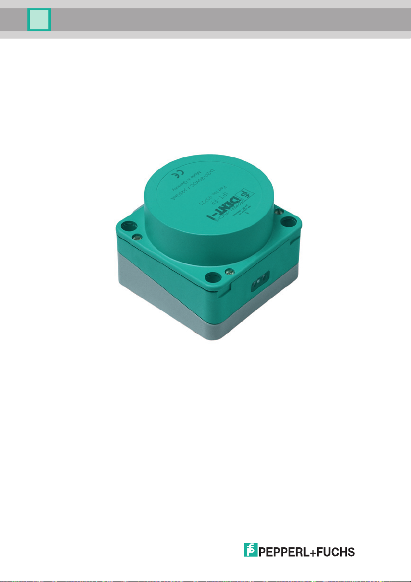
4 Product description
The brand name IDENT-I System P represents a complete identification system. The read/write
station consists of the read/write head IPT*-FP (standard version: IPT1-FP) and the lower
section U-P*-R4 with addressable serial interfaces RS485. With the use of 125 kHz technology,
the system is extensively open for the implementation of other components.
U-P*-R4 stands for:
U-P3-R4 = Standard device with metric ISO thread (EU)
U-P4-R4 = Standard device with NPT pipe thread (USA)
098407 2009-04
8
IPT*-FP WITH U-P*-R4
2
1
3
Product description
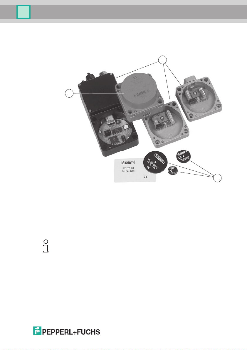
4.1 Product family
The inductive identification system IDENT-I system P from Pepperl+Fuchs offers various
possible combinations of individual components.
1 Read/write station
2 Lower sections
3 Code/data carrier
Note!
Detailed information on the components of the identification system IDENT-I system P can be
found in the sensor systems 1 catalog.
4.1.1 Code/data carrier
A wide assortment of designs is available for the inductive 125 kHz code and data carriers.
Data carriers are available for temperatures up to 300 °C (max. 5 min) in chemical-resistant
housings for installation in metal and in protection class IP68/IP69K. IPC02-... code carriers
offer 40-bit fixcode. IPC03-... data carriers have 928 bits of freely programmable memory and a
non-variable fixcode of 32 bits. The storage area of the IPC03-… can be protected against
unauthorized read and write. 40-bit fixcodes that can be freely determined can be generated
with IPC11-... code carriers. These fixcodes can be generated one time permanently or they
098407 2009-04
can be modifiable.
9

IPT*-FP WITH U-P*-R4
Product description
4.2 Range of application
The system is suited for the following applications:
• Automation
• Material flow control in production
• Acquisition of operating data
• Access control
• Identification of e.g. storage vessels, pallets, work piece carriers, refuse containers, tanks,
containers, etc.
4.3 Delivery package
IPT*-FP contains:
• 1 Read/write head
• CD with documentation (incl. this manual)
1
U-P*-R4
contains:
• Lower section
1
The lower section must be ordered separately.
10
098407 2009-04
IPT*-FP WITH U-P*-R4
2
1
3
DIP-switch
address
Terminating
resistor
Cable gland
+
- 24 V DC
B RS 485
A
PE
2
3
4
5 LSB
OFF
1 MSB
ON
OFF
ON
Product description
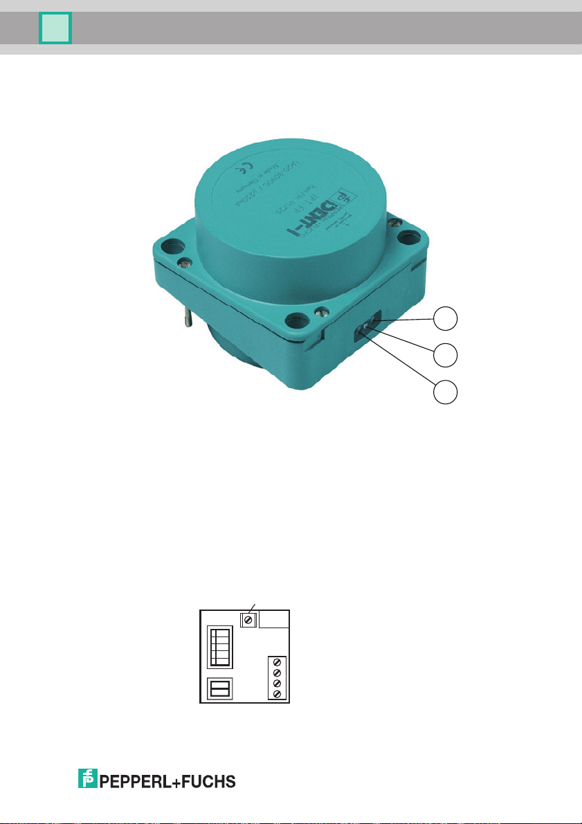
4.4 Display and controls
The following displays and controls are located on the read/write head.
LED display
1 Bus error - red
2 IPC recognized - yellow,
command executed successfully (approx. 1 second)
3 Power on - green
4.5 Interfaces and connections
The following interfaces and connections are located on the lower section U-P*-R4:
098407 2009-04
11
 Loading...