

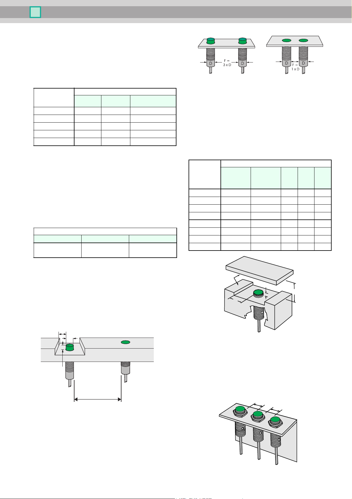
Installation conditions for inductive sensors
D
F
A
B
Non-flush proximity
switches, properly
installed
Flush proximity
switches,
properly installed
B = diameter D
A = 2 x switching distance
Non-flush installed proximity
sensors, F must be 3 times the
housing diameter
Flush installed proximity sensors, F must be equivalent to
the housing diameter
A
C
B
Metal
F
F
Installation condition
The given values are minimum values. They cause changes of the
sensing range less than 10%.
Cylindrical proximity switches
Devices with the same diameter may have different switching distances. The following table shows typical examples:
Diameter
[
mm]
6.5 2 3 3
8 2 3 3
12 2 4 6
18 5 8 12
30 10 15 22
flush not flush
Proximity switches that are installed non-flush
The largest possible switching distance (relative to the diameter) is
chieved by proximity switches that are installed non-flush. An in-
a
ductive proximity switch utilizes coils for generating the electromagnetic field. To achieve a particular direction of the field these coils
are wound in an encapsulated core. Nonetheless, some of this field
will radiate sideways.
To avoid these products with a large range to be already attenuated
by the environment, a clear space must be created around the sensor element complying with the minimum values in the following table.
Dimensions [mm]
A B F
2 x S
n
Switching distance
B = D
increased switching
distance, flush
flush F = D
not flush
F = 3 x D
Sensors with increased switching distance
These sensors with extremely increased switching distance cannot
b
e installed fully flush in metal. They are described as semi-flush in-
stalled.
Distance [mm]
Type
NEB 3-6,5... 1,0 0 6 9 16
NEB 6-12... 2,0 1,0 6 18 18
NEB 12-18... 4,0 1,5 12 36 26
NEB 22-30... 6,0 1,5 22 66 50
NEN 6-8... 8 8 8 18 20
NEN 10-12... 12 12 12 30 30
NEN 20-18... 22 22 22 60 60
NEN 40-30... 40 40 40 120 120
A
(steel, nonfer-
rous heavy
metal)
A
(stainless
steel)
B C F
Proximity switches that are installed flush
Flush installed inductive proximity switches can be used without
earance (A = 0). An advantage is that they are thus mechanically
cl
better protected and less sensitive to erroneous effects than nonflush installed types. The required reduction of the lateral field is
achieved by a special internal shielding. This is at the expense of the
range; these proximity switches only achieve approx. 60 % of the
switching distance of designs for non-flush installation.
Mutual interference
The minimum distances F specified in the table above must be kept
o prevent any mutual interference. If these distances cause prob-
t
lems with the application, then proximity switches with offset frequencies are available upon request. These can then be installed
directly adjacent.
If in doubt please enquire.
Date of issue 2018-02-13
Mutual interference
To prevent the mutual interference between two similar sensors the
inimum distances specified in these tables must be kept.
m
For applications where these distances cannot be maintained proximity switches with offset frequencies are available upon request.
These can then be installed directly adjacent.
Please talk to our product specialist.
1
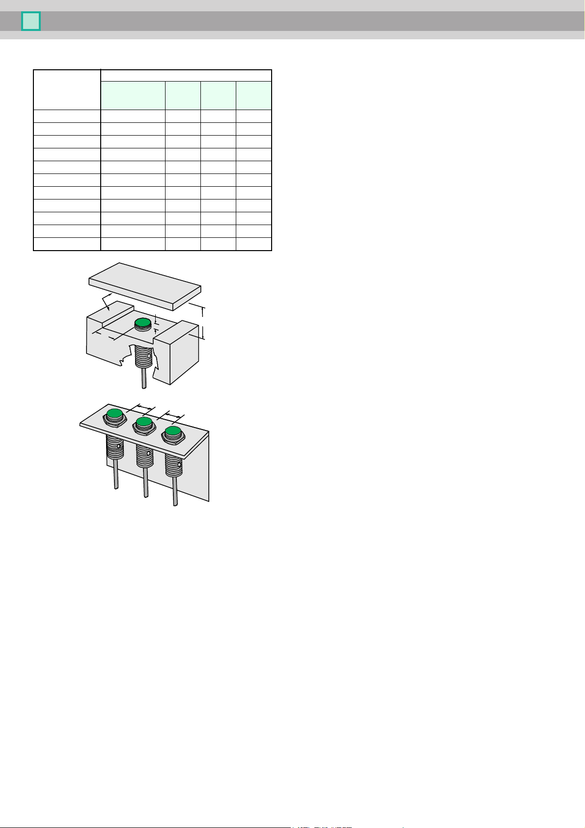
Sensors with Reduction Factor 1
A
C
B
mild steel
F
F
Distance [mm]
Type
NRB2-6,5… 0 5 10 20
NRN6-6,5… 10 20 20 30
NRB2-8G… 0 5 10 15
NRN6-8G… 10 20 20 25
NRB4-12G… 0 5 15 15
NRN10-12G… 20 30 30 50
NRB8-18G… 0 5 15 20
NRB12-18G… 5 15 20 20
NRN15-18G… 25 30 40 60
NRB15-30G… 0 15 20 35
NRN30-30G… 30 45 80 160
A
(for installation in
mild steel)
B C F
Date of issue 2018-02-13
2
 Loading...