

Pepperl+Fuchs IDM-Z1-160-D-1D-J1-SU-N-N0, IDM-Z1-160-D-1D-J1-SU-P-N0, IDM-Z1-260-D-2D-J1-S1-N-N0 User Manual
Page 1

IDM-Z1-160-D-1D-J1-SU-N-N0
IDM-Z1-160-D-1D-J1-SU-P-N0
IDM-Z1-260-D-2D-J1-S1-N-N0
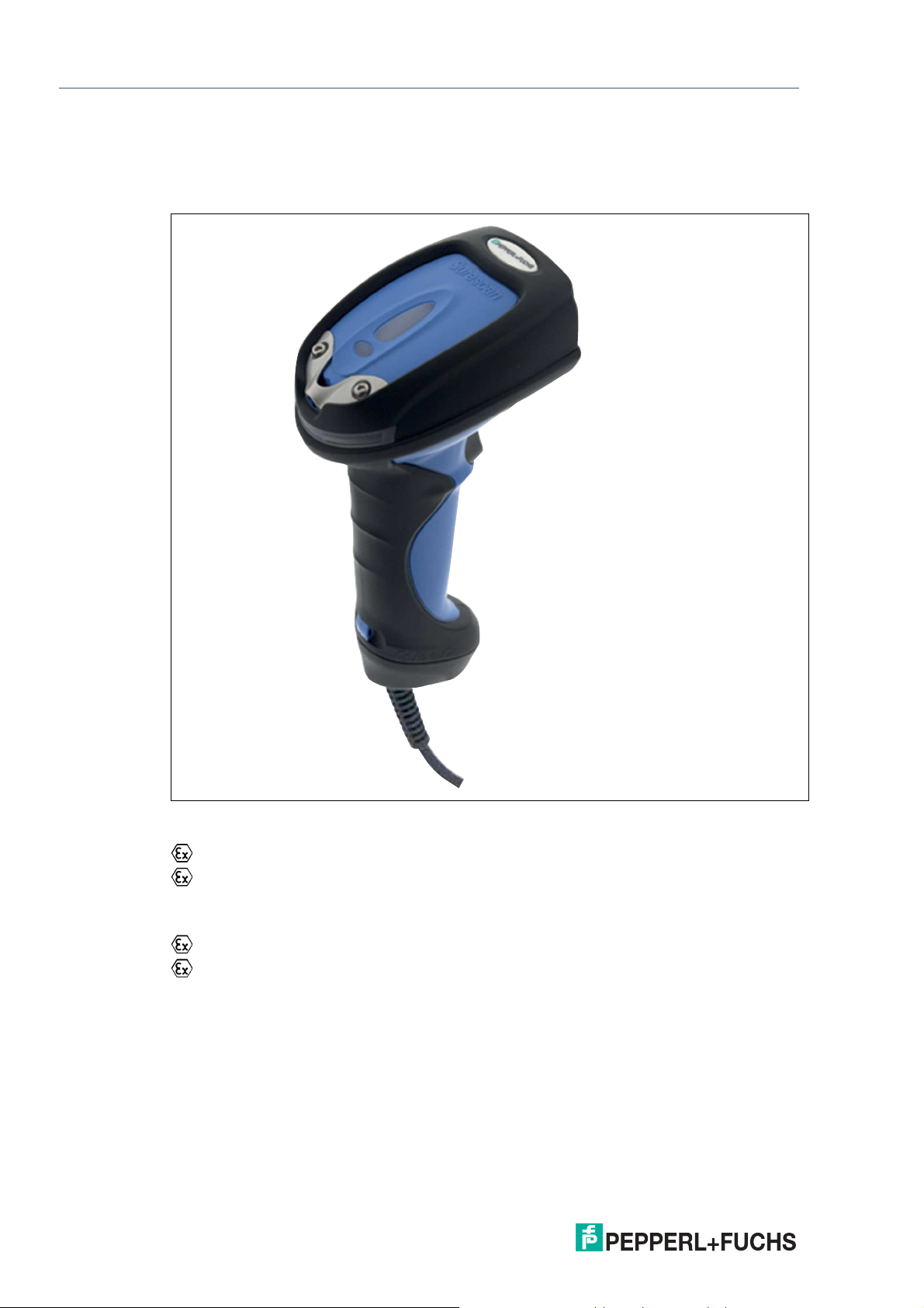
Wired handheld scanner for
use in explosion-hazardous
areas Zone 1/21
Manual
Page 2

With regard to the supply of products, the current issue of the following document is applicable: The
General Terms of Delivery for Products and Services of the Electrical Industry, published by the Central
Association of the Electrical Industry (Zentralverband Elektrotechnik und Elektroindustrie (ZVEI) e.V.)
in its most recent version as well as the supplementary clause: "Expanded reservation of proprietorship"
Worldwide
Pepperl+Fuchs Group
Lilienthalstr. 200
68307 Mannheim
Germany
Phone: +49 621 776 - 0
E-mail: info@de.pepperl-fuchs.com
North American Headquarters
Pepperl+Fuchs Inc.
1600 Enterprise Parkway
Twinsburg, Ohio 44087
USA
Phone: +1 330 425-3555
E-mail: sales@us.pepperl-fuchs.com
Asia Headquarters
Pepperl+Fuchs Pte. Ltd.
P+F Building
18 Ayer Rajah Crescent
Singapore 139942
Phone: +65 6779-9091
E-mail: sales@sg.pepperl-fuchs.com
https://www.pepperl-fuchs.com
Page 3

IDM-Z1-160-D-1D-J1-SU-N-N0, IDM-Z1-160-D-1D-J1-SU-P-N0, IDM-Z1-260-D-2DJ1-S1-N-N0
1 Safety .......................................................................................................................... 4
1.1 Introduction.................................................................................................... 4
1.1.1 Content of this Document .................................................................. 4
1.1.2 Manufacturer...................................................................................... 4
1.1.3 Target Group, Personnel .................................................................... 4
1.1.4 Symbols Used ................................................................................... 5
2 Technical Specifications ........................................................................................... 6
2.1 Explosion protection ..................................................................................... 6
2.2 Technical Data: Handheld Scanner .............................................................. 7
2.3 Use ..................................................................................................................7
3 System Structure....................................................................................................... 8
3.1 Overview......................................................................................................... 8
3.2 IDM-Z1-160-D-1D-J1-* System Structure 1................................................ 10
3.3 IDM-Z1-160-D-1D-J1-* System Structure 2................................................ 11
3.4 IDM-Z1-160-D-1D-J1-* System Structure 3................................................ 12
3.5 IDM-Z1-260-D-2D-J1-S1-N-N0 System Structure 1 ................................... 13
3.6 IDM-Z1-260-D-2D-J1-S1-N-N0 System Structure 2 ................................... 13
3.7 IDM-Z1-260-D-2D-J1-S1-N-N0 System Structure 3 ................................... 14
4 Commissioning........................................................................................................ 16
4.1 Connection of the Wired Handheld Scanners...........................................16
4.2 Supply Module Connection ........................................................................16
4.3 Base connection line RS232....................................................................... 18
4.4 Base connection line USB ..........................................................................19
5 Accessories.............................................................................................................. 21
2019-12
3
Page 4

IDM-Z1-160-D-1D-J1-SU-N-N0, IDM-Z1-160-D-1D-J1-SU-P-N0, IDM-Z1-260-D-2DJ1-S1-N-N0
1 Safety
1.1 Introduction
1.1.1 Content of this Document
This document contains information required to use the product in the relevant phases of the
product life cycle. This may include information on the following:
• Product identification
• Delivery, transport, and storage
• Mounting and installation
• Commissioning and operation
• Maintenance and repair
• Troubleshooting
• Dismounting
• Disposal
Note
For full information on the product, refer to the further documentation on the Internet at
www.pepperl-fuchs.com.
The documentation comprises the following parts:
• This document
• Datasheet
In addition, the documentation may comprise the following parts, if applicable:
• EU-type examination certificate
• EU declaration of conformity
• Attestation of conformity
• Certificates
• Control drawings
• Instruction manual
• Other documents
1.1.2 Manufacturer
Pepperl+Fuchs Group
Lilienthalstraße 200, 68307 Mannheim, Germany
Internet: www.pepperl-fuchs.com
1.1.3 Target Group, Personnel
Responsibility for planning, assembly, commissioning, operation, maintenance, and dismounting lies with the plant operator.
Only appropriately trained and qualified personnel may carry out mounting, installation, commissioning, operation, maintenance, and dismounting of the product. The personnel must have
read and understood the instruction manual and the further documentation.
Prior to using the product make yourself familiar with it. Read the document carefully.
4
2019-12
Page 5
IDM-Z1-160-D-1D-J1-SU-N-N0, IDM-Z1-160-D-1D-J1-SU-P-N0, IDM-Z1-260-D-2DJ1-S1-N-N0
1.1.4 Symbols Used
This document contains symbols for the identification of warning messages and of informative
messages.
Warning Messages
You will find warning messages, whenever dangers may arise from your actions. It is mandatory
that you observe these warning messages for your personal safety and in order to avoid property damage.
Depending on the risk level, the warning messages are displayed in descending order as follows:
Danger!
This symbol indicates an imminent danger.
Non-observance will result in personal injury or death.
Warning!
This symbol indicates a possible fault or danger.
Non-observance may cause personal injury or serious property damage.
Caution!
This symbol indicates a possible fault.
Non-observance could interrupt the device and any connected systems and plants, or result in
their complete failure.
Informative Symbols
Note
This symbol brings important information to your attention.
Action
This symbol indicates a paragraph with instructions. You are prompted to perform an action or
a sequence of actions.
2019-12
5
Page 6
IDM-Z1-160-D-1D-J1-SU-N-N0, IDM-Z1-160-D-1D-J1-SU-P-N0, IDM-Z1-260-D-2DJ1-S1-N-N0
2 Technical Specifications
2.1 Explosion protection
IDM-Z1-160-D-1D-J1-*
II 2G Ex ib IIC T4 Gb
II 2D Ex ib IIIC T135°C Db
IDM-Z1-260-D-2D-J1-*
II 2G Ex ib op is IIB T4 Gb
II 2D Ex ib op is IIIC T135°C Db
Test certificate
IBExU 18ATEX1049
IECEx IBE 18.0008
Manufacturer
Pepperl+Fuchs Group
Lilienthalstraße 200, 68307 Mannheim, Deutschland
info@de.pepperl-fuchs.com
2019-12
6
Page 7
IDM-Z1-160-D-1D-J1-SU-N-N0, IDM-Z1-160-D-1D-J1-SU-P-N0, IDM-Z1-260-D-2DJ1-S1-N-N0
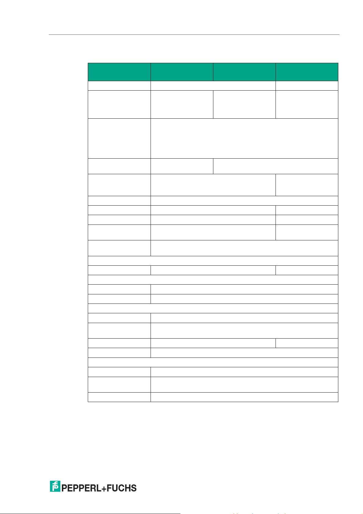
2.2 Technical Data: Handheld Scanner
IDM-Z1-160-D-1DJ1-SU-N-N0
Description Linear imager 2-D imager
Barcode One-dimensional 1-D
(barcode)
Barcode types Code 39, Code 39 Trioptic, Code 32, Code 93, Code 11, Codabar,
Stack codes - PDF417, MicroPDF417, Code 49, Code 16K,
2-D code types - Data Matrix, QR-
Light source LED, visible red light, 630 nm
Scan frequency 500 Hz 60 Hz
Reading distance 20 mm to 850 mm 30 mm to 400 mm
Code resolution
(code-dependent)
Immunity to extraneous light
Electrical data
Interfaces RS232 / RS422 / USB RS232 / USB
Feedback
Visual 2x LED (operating state/read confirmation)
Acoustic Beeper / buzzer (can be switched off)
Ambient conditions
Shock resistance 50 drop tests on concrete from a height of 2 m
Operating temperature
Storage temperature -30 °C to +70 °C -40 °C to +70 °C
Relative humidity 95 % non-condensing
Mechanical data
Degree of protection IP65
Dimensions [W x H x D]104 mm x 185 mm x 76 mm
Code 128, GS1-128 / EAN 128, UPC / EAN / JAN (with addition),
MSI/Plessey, UK/Plessey, IATA, Interleaved 2 of 5, Standard and
Industrial 2 of 5, Matrix 2 of 5, Telepen, GS1 DataBar, Australian Post,
China Post, German Post, US Planet, US Postnet, British Post, Intelligent Mail, Japan Post, Korean Post, Dutch KIX Post
Approx. ≥ 0.076 mm Approx. ≥ 0.13 mm
100,000 lx
-20 °C to +50 °C
IDM-Z1-160-D-1DJ1-SU-P-N0
One-dimensional 1-D
(Barcode and stack
code incl. PDF417)
Composite, Codablock F
IDM-Z1-260-D-2DJ1-S1-N-N0
One-dimensional 1-D
& 2-D
(Barcode and stack
code incl. PDF417)
Code, MicroQR-Code,
Aztec, MaxiCode
2.3 Use
2019-12
Weight Approx. 200 g without connection cable
The handheld scanner is a piece of handheld apparatus.
It enables portable recording and direct data transfer in explosion-hazardous areas. The device
is specifically modified for use in explosion-hazardous areas of zone 1 and zone 21.
7
Page 8

IDM-Z1-160-D-1D-J1-SU-N-N0, IDM-Z1-160-D-1D-J1-SU-P-N0, IDM-Z1-260-D-2DJ1-S1-N-N0
3 System Structure
3.1 Overview
The wired handheld scanners and their accessories are presented in the following overview.
The handheld scanners can be connected to a Pepperl+Fuchs VisuNet operator workstation.
Connection can be either via the external power module or an integrated barrier (applies to VisuNet GXP). The data can be transferred via the network interface of the VisuNet operator workstation to a host PC in the safe area.
Alternatively, the handheld scanners can be connected to a PC or a programmable logic controller (PLC) with the associated power module and operated as "standalone" units.
2019-12
8
Page 9

IDM-Z1-160-D-1D-J1-SU-N-N0, IDM-Z1-160-D-1D-J1-SU-P-N0, IDM-Z1-260-D-2DJ1-S1-N-N0
Figure 3.1 Corded scanners and accessories
2019-12
9
Page 10

IDM-Z1-160-D-1D-J1-SU-N-N0, IDM-Z1-160-D-1D-J1-SU-P-N0, IDM-Z1-260-D-2DJ1-S1-N-N0
Warning!
Wired handheld scanners may only be operated with the specified Pepperl+Fuchs connection
cables!
Handheld scanners may only be operated on the specified Pepperl+Fuchs supply modules/barriers!
The warning messages in this instruction manual and the SICK AG manual (www.SICK.com)
must be observed!
In the following two subchapters, the typical usage cases are described in more detail.
3.2 IDM-Z1-160-D-1D-J1-* System Structure 1
Overview of the complete system structure 1: Wired 1-D handheld scanner IDM-Z1-160-D-1DJ1-SU-N-N0 and IDM-Z1-160-D-1D-J1-SU-P-N0 connected to the power module and the USB
Ex i interface of the VisuNet GXP.
10
Figure 3.2 System structure 1 – 1-D handheld scanner connected to RS232 Ex i VisuNet GXP
interface
Description:
The handheld scanner is designed to be used in explosion-hazardous areas. For proper operation in explosion-hazardous areas, the permissible RS232 cordsets CBL-IDMx60-D-J1-S*
must be used. The intrinsically safe power supply and data transfer is realized via this cable. An
accessory cable DATL-IDM-DB-S-XX00-N0 is required for a connection to the VisuNet GXP in
the AG-XX00 housing. This provides the housing feedthrough and has a connection socket
that fits the scanner connection cable.
2019-12
Page 11

IDM-Z1-160-D-1D-J1-SU-N-N0, IDM-Z1-160-D-1D-J1-SU-P-N0, IDM-Z1-260-D-2DJ1-S1-N-N0
Note
The installation of IDM-Z1-160-D-1D-J1* Barcode Readers to the integrated barrier of the
VisuNet GXP or VisuNet IXD requires the optional interface "3". Please refer to the VisuNet
GXP and VisuNet IXD Datasheets (Module A and B) for further information regarding the
interfaces.
3.3 IDM-Z1-160-D-1D-J1-* System Structure 2
Overview of the complete system structure 2: Wired 1-D handheld scanner IDM-Z1-160-D-1DJ1-SU-N-N0 and IDM-Z1-160-D-1D-J1-SU-P-N0 connected via supply module SK-IDM-Z1-*
to the VisuNet GXP in the hazardous environment. The power supply for the supply module is
in this application located in the safe area.
Figure 3.3 System structure 2 - 1-D handheld scanner connected to the supply module and the USB
Ex e standard interface of the VisuNet GXP
Description:
The handheld scanner is designed to be used in explosion-hazardous areas. For proper operation in explosion-hazardous areas, the permissible USB cordsets CBL-IDMx60-D-J1-U* must
be used. The intrinsically safe power supply and data transfer is realized via this cable. The
connection in this structure uses the supply module SK-IDM-Z1-160-BD-1D-J1-*C-U-N0,
which is connected to the USB Ex e interface of the VisuNet GXP or another VisuNet operator
workstation. Data communication is via the USB Ex e interface, while the handheld scanner is
powered by the supply module and the external power supply is located in the Non-Ex environment.
The handheld scanner and the supply module may be connected and used in explosion- hazardous areas. The current rating of the connection line must be observed.
Note
With the USB-interface version, the maximum total cable length between the host - e.g.,
VisuNet GXP or host PC in the safe area - and the handheld scanner is limited to 5 m! This
includes the scanner cable CBL-IDMx60-D-J1-U*.
2019-12
11
Page 12

IDM-Z1-160-D-1D-J1-SU-N-N0, IDM-Z1-160-D-1D-J1-SU-P-N0, IDM-Z1-260-D-2DJ1-S1-N-N0
Note
This setup is also available for RS232. The maximum total cable length between the host and
the handheld scanner is then 20 m. Make sure to use the compatible RS232 cables.
3.4 IDM-Z1-160-D-1D-J1-* System Structure 3
Overview of the complete system structure 3: Wired 1-D handheld scanner IDM-Z1-160-D-1DJ1-SU-N-N0 and IDM-Z1-160-D-1D-J1-SU-P-N0 connected to the supply module and a host
PC in the safe area.
Figure 3.4 System structure 3 - 1-D scanner connected to supply module and host PC in the safe area
Note
The Supply module is available for RS232 and USB, make sure to use the compatible RS232
or USB cables.
Description:
The handheld scanner is designed to be used in explosion-hazardous areas. For proper operation in explosion-hazardous areas, the permissible USB cordsets CBL-IDMx60-D-J1-U* /
RS232 cordsets CBL-IDMx60-D-J1-S* must be used. The intrinsically safe power supply and
data transfer is realized via this cable. The connection in this structure uses the supply module
SK-IDM-Z1-160-BD-1D-J1-*, which is connected to the communication interface
(USB/RS232) of the host PC in the safe area. Data communication is via the USB/RS232 interface, while the handheld scanner is powered by the supply module and the external power supply is intrinsically safe.
Note
With the USB-interface version, the maximum total cable length between the host - e.g.,
VisuNet GXP or host PC in the safe area - and the handheld scanner is limited to 5 m! This
includes the scanner cable CBL-IDMx60-D-J1-U*.
2019-12
12
Page 13

IDM-Z1-160-D-1D-J1-SU-N-N0, IDM-Z1-160-D-1D-J1-SU-P-N0, IDM-Z1-260-D-2DJ1-S1-N-N0
3.5 IDM-Z1-260-D-2D-J1-S1-N-N0 System Structure 1
Figure 3.5 System structure 1 – 2-D handheld scanner connected to RS232 Ex i VisuNet GXP
Description
The handheld scanner is designed to be used in explosion-hazardous areas. For proper operation in explosion-hazardous areas, the permissible RS232 cordsets CBL-IDMx60-D-J1-S*
must be used. The intrinsically safe power supply and data transfer is realized via this cable. An
accessory cable DATL-IDM-DB-S-XX00-N0 is required for a connection to the VisuNet GXP in
the AG-XX00 housing. This provides the housing feedthrough and has a connection socket
that fits the scanner connection cable.
Note
The installation of the IDM-Z1-260- D-2D-J1-S1-N-N0 Barcode Reader to the integrated barrier
of the VisuNet GXP or VisuNet IXD requires the optional interface "4". Please refer to the
VisuNet GXP and VisuNet IXD Datasheets (Module A and B) for further information regarding
the interfaces.
3.6 IDM-Z1-260-D-2D-J1-S1-N-N0 System Structure 2
Overview of the complete system structure 2: Wired 2-D handheld scanner IDM-Z1-260-D 2DJ1-S1-N-N0 connected to the supply module and the RS232 Ex e interface of the VisuNet GXP.
2019-12
13
Page 14

IDM-Z1-160-D-1D-J1-SU-N-N0, IDM-Z1-160-D-1D-J1-SU-P-N0, IDM-Z1-260-D-2DJ1-S1-N-N0
Figure 3.6 System structure 2
Description:
The handheld scanner is designed to be used in explosion-hazardous areas. For proper operation in explosion-hazardous areas, one of the permissible RS232 cordsets CBL-IDMx60-D-J1S* must be used. The intrinsically safe power supply and data transfer is realized via this cable.
The connection in this structure uses the supply module SK-IDM-Z1-260-D-2D-J1-*C-S-N0,
which is connected to the RS232 Ex e interface of the VisuNet GXP or another VisuNet operator workstation. Data communication is via the RS232 Ex e interface, while the handheld scanner is powered by the supply module and the external power supply is intrinsically safe.
The handheld scanner and the supply module may be connected and used in explosion- hazardous areas. The current rating of the connection line must be observed.
Note
This setup is also available for USB. With the USB-interface version, the maximum total cable
length between the host - e.g., VisuNet GXP or host PC in the safe area - and the handheld
scanner is limited to 5 m! This includes the scanner cable CBL-IDMx60-D-J1-U*. The setup is
identical to the RS232 setup. Make sure to use the compatible USB cables though.
3.7 IDM-Z1-260-D-2D-J1-S1-N-N0 System Structure 3
Overview of the complete system structure 3: Wired 2-D handheld scanner IDM-Z1-260-D-2DJ1-S1-N-N0 connected to the supply module and a host PC in the safe area.
14
2019-12
Page 15

IDM-Z1-160-D-1D-J1-SU-N-N0, IDM-Z1-160-D-1D-J1-SU-P-N0, IDM-Z1-260-D-2DJ1-S1-N-N0
Figure 3.7 System Structure 3
Description:
The 2-D Code Handheld Reader is designed to be used in explosion-hazardous areas. For
proper operation in explosion-hazardous areas, the permissible RS232 cordsets CBL-IDMx60D-J1-S* must be used. The intrinsically safe power supply and data transfer is realized via this
cable. The connection in this structure uses the supply module SK-IDM-Z1-260-D-2D-J1-*C-SN0, which is connected to the RS232 communication interface of the host PC in the safe area.
Data communication is via the RS232 interface, while the 2-D Code Handheld Reader is powered by the supply module and the external power supply is intrinsically safe.
The handheld scanner and the supply module may be connected and used in explosion- hazardous areas. The current rating of the connection line must be observed.
2019-12
15
Page 16

IDM-Z1-160-D-1D-J1-SU-N-N0, IDM-Z1-160-D-1D-J1-SU-P-N0, IDM-Z1-260-D-2DJ1-S1-N-N0
4 Commissioning
4.1 Connection of the Wired Handheld Scanners
Connection of wired handheld scanners
Connect the RJ50 plug on the connection cable CBL-IDMx60* for connecting the handheld
scanner to the power module at the bottom of the scanner. Make sure that they are properly
connected.
Figure 4.1
Connect the male M12 connector of the connection cable CBL-IDMx60*. After plugging
together, make sure that the connection is fully secured with the screw cap.
Figure 4.2
4.2 Supply Module Connection
The terminal assignment is located under the unscrewable opening on the front of the power
module.
Danger!
Do not open the housing in the explosion-hazardous area!
Before the device is put into operation in explosion-hazardous areas, it must be ensured that
the housing is completely closed again and screwed on properly.
16
Only trained and qualified personnel may connect the cables.
2019-12
Page 17

IDM-Z1-160-D-1D-J1-SU-N-N0, IDM-Z1-160-D-1D-J1-SU-P-N0, IDM-Z1-260-D-2DJ1-S1-N-N0
Figure 4.3 Supply module terminal compartment
Connection of the Handheld Scanner to the Supply Module RS232 or
USB via Connector - Plug/Coupling
The terminal assignment is located under the unscrewable opening on the front of the supply
module.
(1) Ex e terminal compartment to connect the power supply and the data line
(2) Ex i terminal compartment to connect the consumers (scanner)
Figure 4.4 Supply module terminal compartment
External power module connection lines:
Data cables
Supply line
(see accessories in the appendix)
The blue base connection cable is delivered pre-assembled with the supply module SK-IDMZ1-*. The cable consists of a M12 connector plug and a 3-core cable. The individual cores are
numbered (printed on the core insulation) and must be connected as follows to the intrinsically
safe terminals of the supply module.
2019-12
USB: 0.2 mm2 – 2.5 mm2, 4-core
RS232: 0.2 mm2 – 2.5 mm2, 3-core
0.2 mm2 – 2.5 mm2, 3-core
17
Page 18

IDM-Z1-160-D-1D-J1-SU-N-N0, IDM-Z1-160-D-1D-J1-SU-P-N0, IDM-Z1-260-D-2DJ1-S1-N-N0
Figure 4.5
Figure 4.6 Intrinsically safe terminal compartment of the supply module after removing the connector
connection cores
4.3 Base connection line RS232
Assignment of pre-installed base connection cable to supply module (RS232)
Assignment of pre-assembled connection coupling Supply module terminal compartment
Pin Core designation Designation Number
3 3 RxD X9
2 2 GND X12
1 1 +UB X13
Direct Connection of the Handheld Scanner without a Plug/Coupling to
the Supply Module with RS232 Interface
The handheld scanner can be connected directly to the supply module without using the blue
connection cable.
The assignment of the serial handheld scanner cable is outlined in the following table
GND X10
PE X11
18
2019-12
Page 19

IDM-Z1-160-D-1D-J1-SU-N-N0, IDM-Z1-160-D-1D-J1-SU-P-N0, IDM-Z1-260-D-2DJ1-S1-N-N0
Figure 4.7
Assignment of connection cable CBL-IDM-x61* to supply module (RS232)
Cordset assignment Supply module terminal compartment
RJ50 pinout Strand color Designation Assignment
6 White TxD X9
X10
X11
4 Brown GND X12
7 Yellow +UB X13
Note
Information relating to programming from the SICK AG manual (www.SICK.com) is required for
the complete commissioning of the handheld scanner.
4.4 Base connection line USB
Pinout of connector plug
Pin Designation
3 D+
2 D-
4 GND
1 +UB
Connection of USB connection cable to supply module
Pre-assembled connection coupling Terminal compartment
Pin Core Designation Number
3 3 D+ X9
2 4 D- X10
4 2 GND X12
1 1 +UB X13
PE X11
2019-12
19
Page 20

IDM-Z1-160-D-1D-J1-SU-N-N0, IDM-Z1-160-D-1D-J1-SU-P-N0, IDM-Z1-260-D-2DJ1-S1-N-N0
Direct Connection of the Handheld Scanner without a Plug/Coupling to
the Supply Module with USB Interface
Figure 4.8
Handheld scanner cordset
Cordset assignment Supply module terminal compartment
RJ50 pinout Strand color Designation Assignment
2 Green D+2SL X9
10 White D-2SL X10
X11
7 Black GND X12
4 Brown +UB X13
Note
Information relating to programming from the SICK AG manual (www.SICK.com) is required for
the complete commissioning of the handheld scanner.
20
2019-12
Page 21

IDM-Z1-160-D-1D-J1-SU-N-N0, IDM-Z1-160-D-1D-J1-SU-P-N0, IDM-Z1-260-D-2DJ1-S1-N-N0
5 Accessories
Corded Handheld Reader Mounting Accessories
Item number Product name Description Photo
#548267 SCANNER-HOLDER-
U1-XX00-N0
#548268 SCANNER-HOLDER-
U1-AG1-N0
Scanner holder compatible with Housing
AG-XX00
Material: Stainless steel AISI 316L
(1.4404)
Compatible with IDMx6x, ecom IdentEx
01 and PSCAN
Prepared for mounting to right side of
housing
Scanner holder compatible with Housing
AG1
Material: Stainless steel AISI 316L
(1.4404)
Compatible with IDMx6x, ecom IdentEx01 and PSCAN
Prepared for mounting to right side of
housing
#548353 SCANNER-HOLDER-
IDMx6x-TRIPOD
#548354 SCANNER-HOLDER-
IDMx6x-DESKTOP
Tripod Scanner holder
Compatible to IDMx6x code scanner
Desktop Scanner holder
Compatible to IDMx6x code scanner
2019-12
21
Page 22

IDM-Z1-160-D-1D-J1-SU-N-N0, IDM-Z1-160-D-1D-J1-SU-P-N0, IDM-Z1-260-D-2DJ1-S1-N-N0
Corded Handheld Reader Accessories for VisuNet HMI Applications
Suitable for Zone 1/21 & Zone 2/22
Item number Product name Description
#548333 CBL-IDMx60-D-J1-S-
S18-N0
#548334 CBL-IDMx60-D-J1-S-
C38-N0
#548335 CBL-IDM160-D-J1-U-
S18-N0
#548336 CBL-IDM160-D-J1-U-
C38-N0
#548376 DATL-IDM-DB-S-
XX00-N0
Connection cable for
corded code readers
Interface: RJ50
(Reader) with additional sealing ring to
M12 male connector
Protocol: Serial
Compatible with IDMZx-x60-D* readers
Connection cable for
corded code readers
Interface: RJ50
(Reader) with additional sealing ring to
M12 male connector
Protocol: USB
Compatible with IDMZx-x60-D* readers
Connector cable for
wired 1D Scanner
IDM-Z1-160-D-1D-J1S-* (S3-Interface
required) and 2D
Scanner IDM-Z2-260D-2D-J1-S* (S4-interface required) compatible with Housing
AG-XX00-* and AG1 4-wire with ferrules IDM Scanner connection via M12-connector - Note: Supports
only RS232 Scanner/Basestation
Cable
Photo
Straight 1.8 m
length
Coiled 3.8 m
length
Straight 1.8 m
length
Coiled 3.8 m
length
1.0 m length
22
2019-12
Page 23

IDM-Z1-160-D-1D-J1-SU-N-N0, IDM-Z1-160-D-1D-J1-SU-P-N0, IDM-Z1-260-D-2DJ1-S1-N-N0
Supply module
Ex-protection: ATEX&IECEx Zone 1/21
Item number Product name Description Photo
#70115393 SK-IDM-Z1-160-BD-
1D-J1-DC-S-N
#70115394 SK-IDM-Z1-160-BD-
1D-J1-DC-U-N
#70115395 SK-IDM-Z1-160-BD-
1D-J1-AC-S-N
#70115396 SK-IDM-Z1-160-BD-
1D-J1-AC-U-N
Barrier for corded 1D reader & base station
Input: 24 V DC
Protocol: RS-232/422/485 Ex e (to host
device)
Compatible with IDM-Z1-160-D-1D-J1*
and IDM-Z1-x61-B-J1* with serial connection cables
incl. short setup cable with M12 female
socket
Barrier for corded 1D reader & base station
Input: 24 V DC
Protocol: USB Ex e (to host device)
Compatible with IDM-Z1-160-D-1D-J1*
and IDM-Z1-x61-B-J1* with USB connection cables
incl. short setup cable with M12 female
socket
Barrier for corded 1D reader & base station
Input: 24 V DC
Protocol: RS-232/422/485 Ex e (to host
device)
Compatible with IDM-Z1-160-D-1D-J1*
and IDM-Z1-x61-B-J1* with serial connection cables
incl. short setup cable with M12 female
socket
Barrier for corded 1D reader & base station
Input: 230 V AC
Protocol: USB Ex e (to host device)
Compatible with IDM-Z1-160-D-1D-J1*
and IDM-Z1-x61-B-J1* with USB connection cables
incl. short setup cable with M12 female
socket
2019-12
23
Page 24

IDM-Z1-160-D-1D-J1-SU-N-N0, IDM-Z1-160-D-1D-J1-SU-P-N0, IDM-Z1-260-D-2DJ1-S1-N-N0
Ex-protection: ATEX&IECEx Zone 1/21
Item number Product name Description Photo
#70115397 SK-IDM-Z1-260-D-
2D-J1-DC-S-N
#70115398 SK-IDM-Z1-260-D-
2D-J1-DC-U-N
#70115399 SK-IDM-Z1-260-D-
2D-J1-AC-S-N
#70115400 SK-IDM-Z1-260-D-
2D-J1-AC-U-N
Barrier for corded 2D reader Input: 24 V
DC
Protocol: RS-232/422/485 Ex e (to host
device)
Compatible with IDM-Z1-260-D-2D-J1*
and serial connection cables
incl. short setup cable with M12 female
socket
Barrier for corded 2D reader
Input: 24 V DC
Protocol: USB Ex e (to host device)
Compatible with IDM-Z1-260-D-2D-J1*
and USB connection cables
incl. short setup cable with M12 female
socket
Barrier for corded 2D reader
Input: 230 V AC
Protocol: RS-232/422/485 Ex e (to host
device)
Compatible with IDM-Z1-260-D-2D-J1*
and serial connection cables
incl. short setup cable with M12 female
socket
Barrier for corded 2D reader
Input: 230 V AC
Protocol: USB Ex e (to host device)
Compatible with IDM-Z1-260-D-2D-J1*
and USB connection cables
incl. short setup cable with M12 female
socket
Cable accessories
Item Number Product Name Description Cable
#548379 S-RN2/DB9-5-N0 RS232 cable with SUB-D9 plug (female)
and open cable ends with wire end ferrules
#548380 S-RN2/DB9-20-N0 RS232 cable with SUB-D9 plug (female)
and open cable ends with wire end ferrules
#193077 DATL-A3-1.5-1 Supply line for 90 – 240 VAC supply
3 x 1.5 mm², diameter 8.1 mm
Assembly 6 x 1.5 mm² wire end ferrules
#913886 S-UN2/USB USB cable with USB Type A plug (male)
and open cable ends with wire end ferrules
5 m length
20 m length
1 m length
24
2019-12
Page 25

Pepperl+Fuchs Qua lit y
Download our latest poli cy he re:
www.pepperl-fuchs.com/quali ty
© Pepperl+Fuchs · Subject to modifications
www.pepperl-fuchs.com
Printed in Germany / DOCT-6092A
 Loading...