

Pepperl+Fuchs IPT FP, IDENT-I system P IPT FP Series, IDENT-I system P IPT1-FP, IDENT-I system P U-P6-B5-V Series Manual
Page 1
MANUAL
IPT*-FP WITH U-P6-B5
Read/write station with
INTERBUS interface
FACTORY AUTOMATION
Page 2

IPT*-FP WITH U-P6-B5
1 Introduction..................................................................4
2 Declaration of conformity ...........................................5
2.1 CE conformity ........................................................................................... 5
3 Safety............................................................................6
3.1 Symbols relevant to safety ...................................................................... 6
3.2 Intended use.............................................................................................. 6
3.3 General safety instructions...................................................................... 6
3.4 Operational reliability and monitoring.................................................... 7
4 Product description.....................................................8
4.1 Product family........................................................................................... 9
4.1.1 Code/data carrier ........................................................................................ 9
4.2 Range of application ...............................................................................10
4.3 Delivery package......................................................................................10
4.4 Device characteristics.............................................................................10
4.5 Display and controls ...............................................................................11
4.6 Diagnostic LEDs ......................................................................................11
4.7 Interfaces and connections ................................................................... 12
5 Installation..................................................................13
5.1 Storage and transport ............................................................................ 13
5.2 Unpacking ............................................................................................... 13
5.3 EMC concept ........................................................................................... 13
5.4 Device connection .................................................................................. 15
5.4.1 Voltage supply .......................................................................................... 15
5.4.2 Earth connection....................................................................................... 16
5.4.3 INTERBUS Ring termination .................................................................... 17
5.4.4 Cable lengths............................................................................................ 17
5.4.5 Cable ........................................................................................................ 17
5.4.6 Transfer rate changeover.......................................................................... 18
2
Page 3

IPT*-FP WITH U-P6-B5
6 Commissioning ......................................................... 19
6.1 Installation check ....................................................................................19
6.2 Preliminary considerations ....................................................................20
6.3 Self test ....................................................................................................20
7 Operation on the INTERBUS.................................... 21
7.1 General information on INTERBUS........................................................21
7.2 Outline of the commands and data on the INTERBUS ........................21
7.3 General command information ..............................................................21
7.3.1 Software information .................................................................................21
7.3.2 Command overview...................................................................................23
7.4 System commands..................................................................................25
7.5 Read/write commands ............................................................................29
7.5.1 Read data..................................................................................................29
7.5.2 Write data ..................................................................................................33
7.6 Read only code........................................................................................37
7.7 Special command modes .......................................................................41
7.7.1 IPC03 configuration...................................................................................41
7.7.2 Password mode with IPC03 ......................................................................51
7.7.3 Write fixed code IPC10 ..............................................................................54
7.8 Legend......................................................................................................58
7.9 Error/Status messages ...........................................................................59
8 Technical specifications .......................................... 60
8.1 Read/write station IPT*-FP......................................................................60
8.2 Read/write distances IPT*-FP.................................................................61
8.3 U-P6B5 lower section..............................................................................62
3
Page 4

IPT*-FP WITH U-P6-B5
Introduction
1 Introduction
Congratulations
You have chosen a device manufactured by Pepperl+Fuchs. Pepperl+Fuchs develops,
produces and distributes electronic sensors and interface modules for the market of
automation technology on a worldwide scale.
Before you install this device and put it into operation, please read the operating instructions
thoroughly. The instructions and notes contained in this operating manual will guide you stepby-step through the installation and commissioning to ensure the trouble-free usage of this
product. This is useful to you, because with this you:
• support the safe operation of the device
• can utilize the device’s entire range of functions
• reduce faulty operation and the associated errors
• reduce costs from downtime and incidental repairs
• increase the effectiveness and operating efficiency of your plant.
Store this operating manual somewhere safe in order to have it available for future work on the
device.
Directly after opening the packaging, please ensure that the device is intact and that the
package is complete.
Symbols used
The following symbols are used in this manual:
Note!
This symbol draws your attention to important information.
Handling instructions
You will find handling instructions beside this symbol
Contact
If you have any questions about the device, its functions, or accessories, please contact us at:
Pepperl+Fuchs GmbH
Lilienthalstraße 200
68307 Mannheim
Telephone: +49 621 776-4411
Fax: +49 621 776-274411
E-Mail: fa-info@pepperl-fuchs.com
102696 2009-03
4
Page 5

IPT*-FP WITH U-P6-B5
Declaration of conformity
2 Declaration of conformity
2.1 CE conformity
This product was developed and manufactured under observance of the applicable European
standards and guidelines.
Note!
A declaration of conformity can be requested from the manufacturer.
102696 2009-03
5
Page 6

IPT*-FP WITH U-P6-B5
Safety
3 Safety
3.1 Symbols relevant to safety
Danger!
This symbol indicates a warning about a possible danger.
In the event the warning is ignored, the consequences may range from personal injury to death.
Warning!
This symbol indicates a warning about a possible fault or danger.
In the event the warning is ignored, the consequences may course personal injury or heaviest
property damage.
Caution!
This symbol warns of a possible fault.
Failure to observe the instructions given in this warning may result in the devices and any
connected facilities or systems develop a fault or fail completely.
3.2 Intended use
Together, the devices IPT*-FP and U-P6-B5 of the inductive identification system IDENT-I
system P comprise a read/write station..
Always operate the device as described in these instructions to ensure that the device and
connected systems function correctly. The protection of operating personnel and plant is only
guaranteed if the device is operated in accordance with its intended use.
3.3 General safety instructions
Only instructed specialist staff may operate the device in accordance with the operating
manual.
Independent interventions and separate modifications are dangerous and will void the warranty
and exclude the manufacturer from any liability. If serious faults occur, stop using the device.
Secure the device against inadvertent operation. In the event of repairs, send the device to
Pepperl+Fuchs.
The connection of the device and maintenance work when live may only be carried out by a
qualified electrical specialist.
The operating company bears responsibility for observing locally applicable safety regulations.
Store the not used device in the original packaging. This offers the device optimal protection
against impact and moisture.
Note!
Electronic waste is hazardous waste. Observe local disposal regulations.
6
102696 2009-03
Page 7

IPT*-FP WITH U-P6-B5
Safety
3.4 Operational reliability and monitoring
The devices IPT*-FP and U-P6-B5 of the inductive identification system IDENT-I System P
operate on a microprocessor level. Device status is reported via LEDs on the front side on the
IPT*-FP read station and in the U-P6-B5 lower section terminal compartment.
In addition, the INTERBUS functionality can be tested by querying the status information or via
specific commands to test the device. Device error or the failure of a read/write station, for
example, can be recognized and reported by the INTERBUS master in this way.
102696 2009-03
7
Page 8
IPT*-FP WITH U-P6-B5
Product description
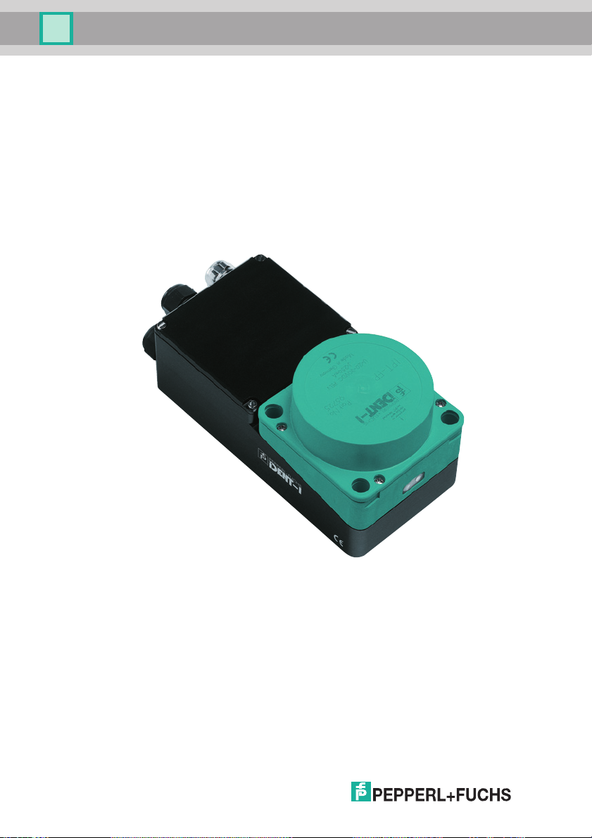
4 Product description
The brand name IDENT-I System P represents a complete identification system. The read/write
station consists of the read/write head IPT*-FP (standard version: IPT1-FP) and the lower
section U-P6-B5 with INTERBUS interface. With the use of 125 kHz technology, the system is
extensively open for the implementation of other components.
The lower section operates as a passive node (Slave). It is therefore restricted to use on the
cyclically read process data channel. The device assigns 5 words to each 16 bits (10 bytes).
The acyclically read parameter channel of the INTERBUS protocol is not assigned.
102696 2009-03
8
Page 9
IPT*-FP WITH U-P6-B5
2
1
3
Product description
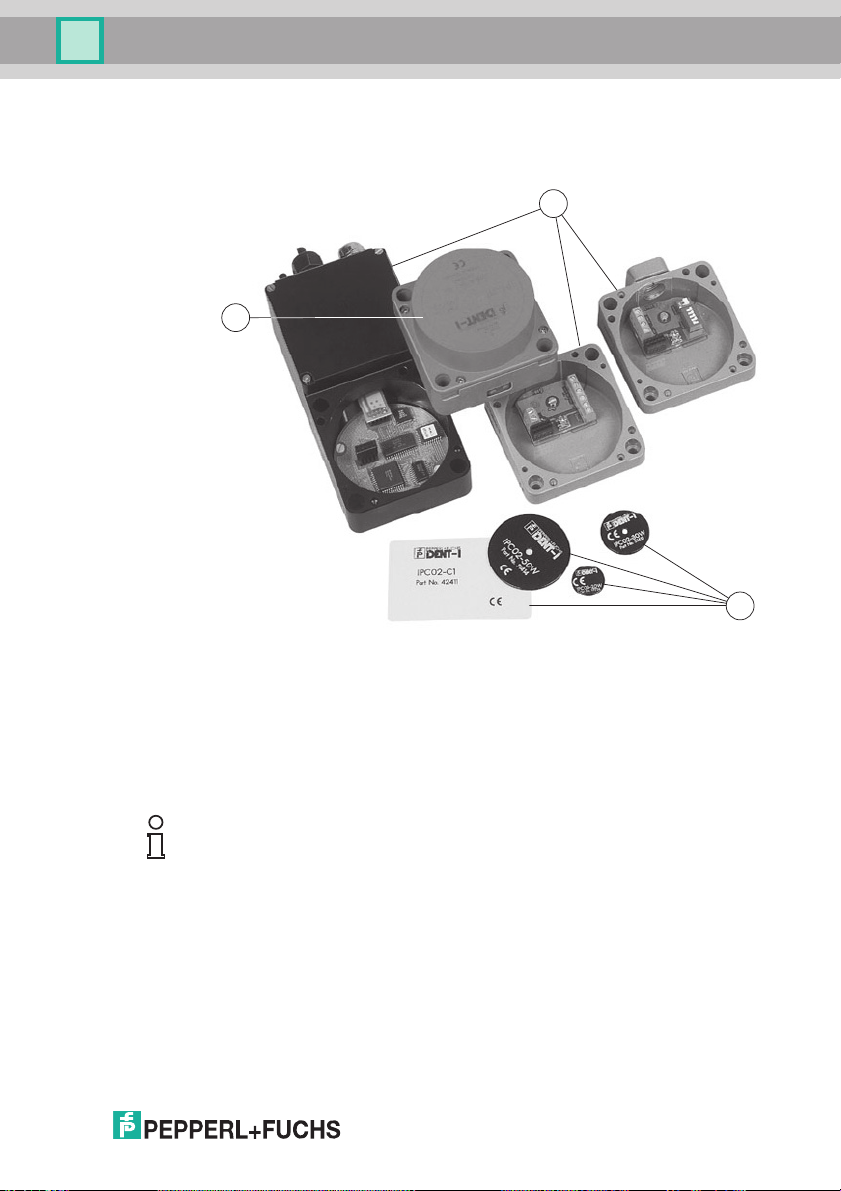
4.1 Product family
The inductive identification system IDENT-I system P from Pepperl+Fuchs offers various
possible combinations of individual components.
1 Read/write station
2 Lower sections
3 Code/data carrier
Note!
Detailed information on the components of the identification system IDENT-I system P can be
found in the sensor systems 1 catalog.
4.1.1 Code/data carrier
A wide assortment of designs is available for the inductive 125 kHz code and data carriers.
Data carriers are available for temperatures up to 300 °C (max. 5 min) in chemical-resistant
housings for installation in metal and in protection class IP68/IP69K. IPC02-... code carriers
offer 40-bit fixcode. IPC03-... data carriers have 928 bits of freely programmable memory and a
non-variable fixcode of 32 bits. The storage area of the IPC03-… can be protected against
unauthorized read and write. 40-bit fixcodes that can be freely determined can be generated
with IPC11-... code carriers. These fixcodes can be generated one time permanently or they
102696 2009-03
can be modifiable.
9
Page 10

IPT*-FP WITH U-P6-B5
Product description
4.2 Range of application
The system is suited for the following applications:
• Automation
• Material flow control in production
• Acquisition of operating data
• Access control
• Identification of e.g. storage vessels, pallets, work piece carriers, refuse containers, tanks,
containers, etc.
4.3 Delivery package
IPT*-FP contains:
• 1 Read/write head
• CD with documentation (incl. this manual)
1
U-P6-B5
contains:
• Lower section
• 1 cover
• 2 ring terminals
• 1 earthing screw
• 1 serrated lock washer
1 sticker
1
The lower section must be ordered separately.
4.4 Device characteristics
The lower section U-P6-B5 is the interface with the INTERBUS remote bus.
• Supply voltage with galvanic isolation
• Bus interfaces with functional isolation accordant with EN 50178.
• Connection of the field bus via EMV-PG9 and screw terminals
• Addressing by means of physical position of the station in the system
• Display LEDs (on the front of the read/write station IPT*-FP)
• Diagnostic LEDs
• The lower section operates as a passive node (Slave). It is therefore restricted to use on
the cyclically read process data channel. The device assigns 5 words to each 16 bits (10
bytes). The acyclically read parameter channel of the INTERBUS protocol is not assigned.
10
102696 2009-03
Page 11

IPT*-FP WITH U-P6-B5
2
1
3
Product description
4.5 Display and controls
The following displays and controls are located on the read/write head.
LED display
1 Bus error - red
2 IPC recognized - yellow,
command executed successfully (approx. 1 second)
3 Power on - green
4.6 Diagnostic LEDs
The following diagnostic LEDs are located in the terminal compartment of the lower section:
LED Color Meaning
US green "Power on"
RC green "Remote Check"
BA green "Bus Acitve"
RD yellow "Remotebus Disabled"
102696 2009-03
11
Page 12
IPT*-FP WITH U-P6-B5
Product description
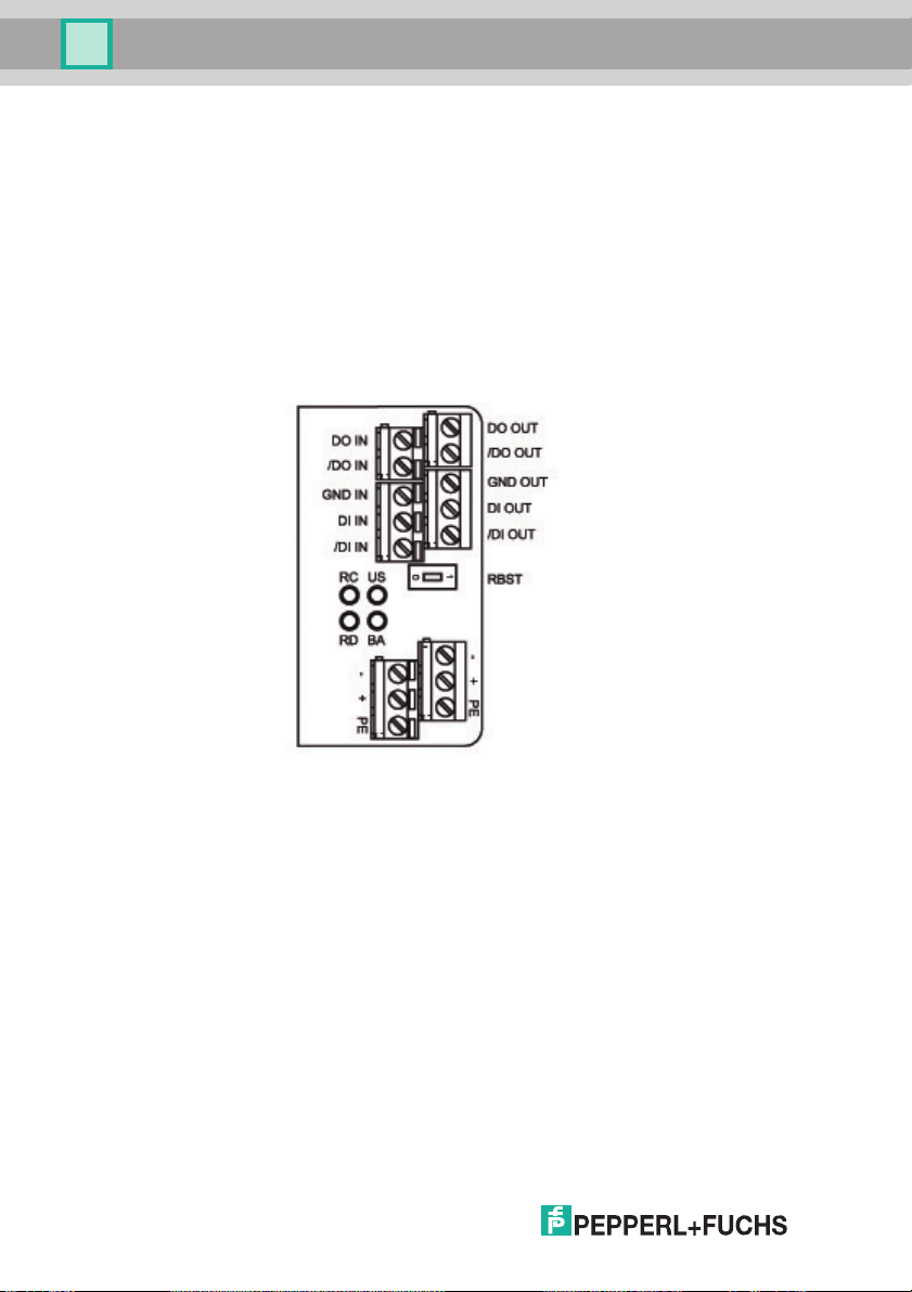
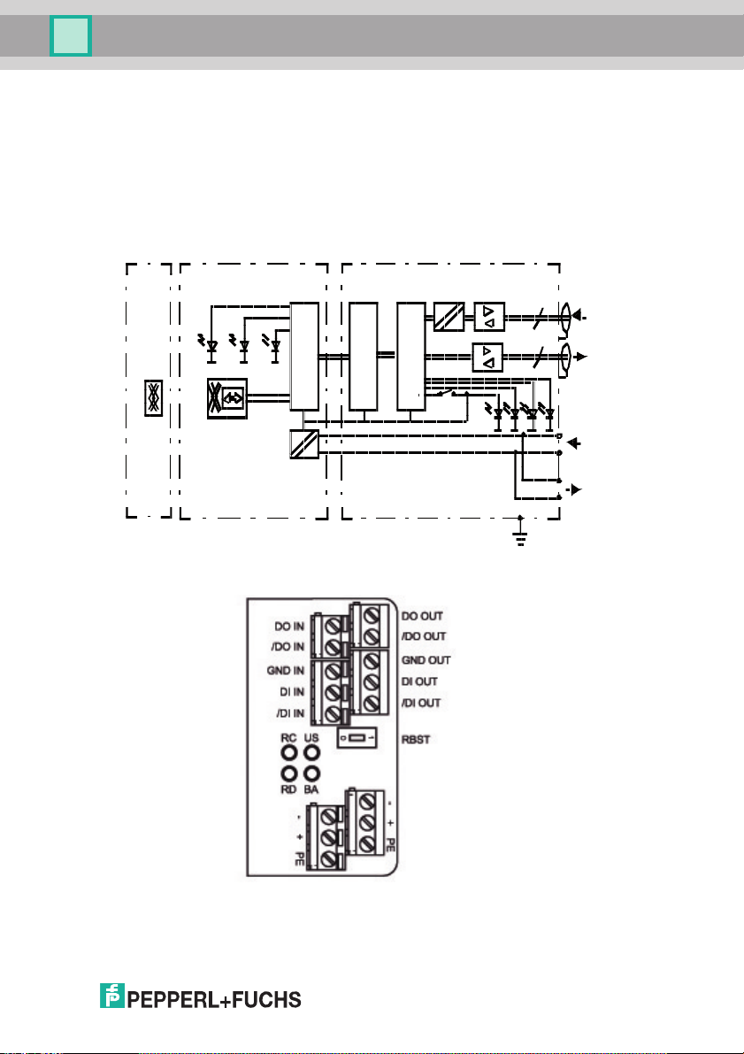
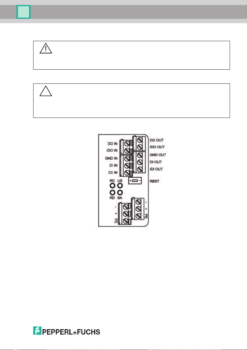
4.7 Interfaces and connections
The following interfaces and connections are located on the lower section U-P6-B5:
12
102696 2009-03
Page 13

IPT*-FP WITH U-P6-B5
Installation
5 Installation
5.1 Storage and transport
For storage and transport purposes, package the unit using shockproof packaging material and
protect it against moisture. The best method of protection it to package the unit using the
original packaging. Furthermore, ensure that the ambient conditions are within permissible
range.
5.2 Unpacking
Check the product for damages while unpacking. In the event of damage to the product, inform
the post office or parcel service and notify the supplier.
Check the package contents with your purchase order and the shipping documents for:
• Delivery quantity
• Device type and version in accordance with the type plate
• Accessories
• Manual/manuals
Retain the original packaging in case the device must be stored or shipped again at a later
date.
Should you have any questions, please direct them to Pepperl+Fuchs.
5.3 EMC concept
The screening of cables provides for the discharge of electromagnetic interference. When
screening a cable, both sides of the screen must be connected to the earth with low resistance
and low inductance.
Note!
If cables with double screening are used, e.g. wire meshing and metalized foil, the screens
must be connected together at the ends, with low resistance, when making up the cable.
Power supply cables are the source of much interference, e.g. the starting current of 3-phase
electric motors. For this reason, the parallel laying of power supply cables with data and signal
cables should be avoided, particularly in the same cable duct.
102696 2009-03
13
Page 14
IPT*-FP WITH U-P6-B5
1
2
3
Installation
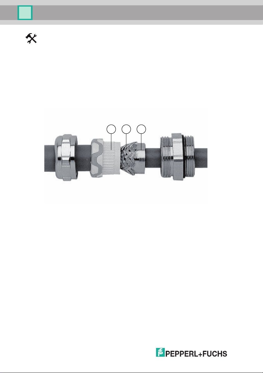
Connect screening with the PG cable gland of the lower section
In order to connect the screening with the PG cable gland on the lower section and in so doing
satisfy the EMC requirements in accordance with DIN VDE 0871/6.78, the following steps must
be carried out:
1. Strip the outer sheathing of the cable end over a length of approx. 10 mm.
2. Lightly flare the screen (2).
3. Slide the screen (2) over the cone (3).
4. Pull the seal insert (1) over the screen (2) and cone (3).
5. Screw on the PG cable gland.
14
102696 2009-03
Page 15
IPT*-FP WITH U-P6-B5
rt ge gn
mP1
mP2
SU PI
OUT
IN
OUT
I P T-FP
U-P6-B5
IP C
20 ... 30 VDC
IN
PELV
3
U
s
RC
BA
RD
gn gn gn ge
5
5
RBST
Installation
5.4 Device connection
5.4.1 Voltage supply
The electrical connection of the lower section is made via screw terminals. The maximum core
cross-section of the cable is 1.5 mm
Connect up the INTERBUS and the supply voltage as described in the connection diagram and
in the terminal assignment list.
2
.
102696 2009-03
15
Page 16
IPT*-FP WITH U-P6-B5
12 43
Installation
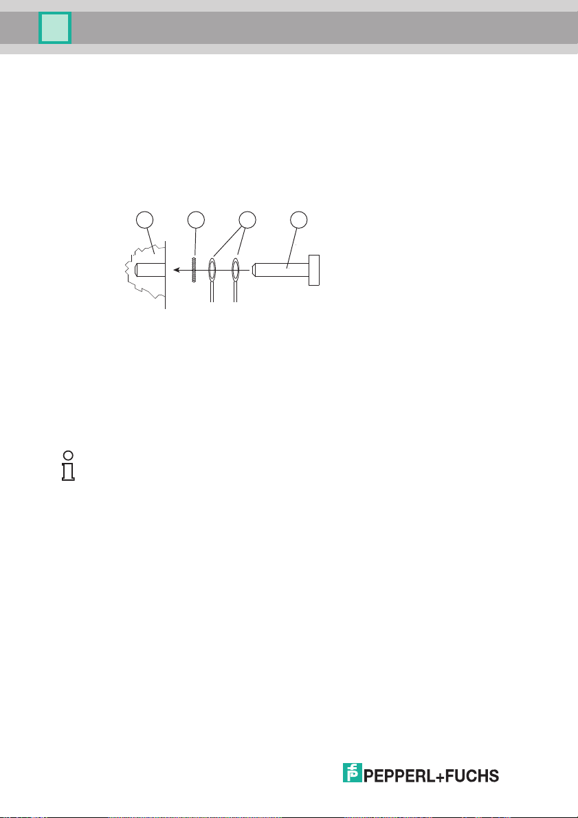
5.4.2 Earth connection
The internal PE connection of the lower section is conductively connected with the housing.
However, from the point of view of screening, connection to the outside of the housing is
preferable.
The external earth connection of the lower section is located lower left, adjacent to the cable
entries. The PE conductor is screwed to the housing with a crimp connector. In order to
guarantee safe earthing, the serrated washer must be mounted between the crimp connector
and the housing.
1 Housing
2 Serrated lock washer
3 Crimp connector
4 Lock screw
A cross-section of at least 4 mm
2
is recommended for the PE conductor lead.
Note!
The “CMD” manufacturer-independent program is available for planning, commissioning and
diagnosing INTERBUS networks.
Details of this program and information on the general theme of INTERBUS are available from:
INTERBUS-Club
Postfach 11 08
D-32817 Blomberg
Tel: +49 52 35/ 34 21 00
Fax: +49 52 35/ 34 12 34
16
102696 2009-03
Page 17

IPT*-FP WITH U-P6-B5
1
0
Bus not
terminated
Bus terminated
Installation
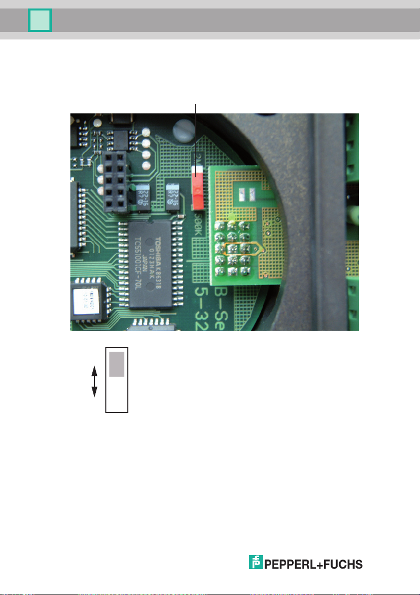
5.4.3 INTERBUS Ring termination
A characteristic of the INTERBUS system is its physical ring structure. Each connected device
lies in the bus between two other stations. If this is not the case, for example, at the end of a
branch with a bus terminal, then the ring line must be closed in the respective device.
The DIP switch for the ring termination, designated “RBST”, must be set to the correct position
(see Figure 5.3). The ring termination switch is located in the terminal compartment in the lower
section U-P6-B5.
Ring termination switch
Note!
The ring termination must only be activated if the device is positioned at the end of an open
branch! Otherwise all the following devices will be cut off from the communication.
5.4.4 Cable lengths
5.4.5 Cable
102696 2009-03
Depending on the type of cable used and the magnitude of the external interference, the
distance between two devices can be up to 400 meters. The total expansion of an INTERBUSSystem can be up to 12.8 kilometers. The number of devices connected to the bus is limited to
512.
The following INTERBUS remote bus cables should be used:
Parameter Standard Highly flexible
Cable construction Twisted pairs/i.e. 2-core, common screening
Conductor crosssection
Operating capacity 60 pF/m
Impedance 120 Ω at 64 KHz/100 Ω at 1 MHz
Use only screened cables constructed as twisted pairs. The best possible EMC interference
immunity can only be achieved by using screened cables.
3 x 2 x 0.22 mm
2
3 x 2 x 0.25 mm
Suitable for laying
underground
2
3 x 2 x 0.22 mm
2
17
Page 18
IPT*-FP WITH U-P6-B5
2 MBit/s
500 kBit/s
Installation
5.4.6 Transfer rate changeover
An internal slide switch enables the transfer rate to be adjusted to match that of the bus. This
allows the two values of 500 kbit/s and 2 Mbit/s to be set.
Schiebeschalter
The status is preset at 2 MBit/s on delivery.
102696 2009-03
18
Page 19
IPT*-FP WITH U-P6-B5
Commissioning
6 Commissioning
Warning!
Before commissioning, ensure that the plant is not in danger relating to device malfunction, e.g.
from uncontrollable triggered processes.
6.1 Installation check
Caution!
Before commissioning, check once again that the connections are correct.
Before commissioning, familiarize yourself with the system of communication between your
INTERBUS and the read/write station. Commissioning requires accurate knowledge of
INTERBUS and the programming of your master device.
After connecting the supply voltage the "power on" LED on the read station and the green "US"
LED on the lower section must light. Configure the read/write station with the described system
commands. “Autodetect” is set as the data carrier type.
The transfer speed on the INTERBUS is 500 kbit/s or 2 Mbit/s.
102696 2009-03
19
Page 20

IPT*-FP WITH U-P6-B5
Commissioning
6.2 Preliminary considerations
Due to the complexity of field bus programming with the INTERBUS it is very difficult to make
generally valid statements about commissioning.
A very important aspect of the operation of an inductive identification system with the lower
section on the INTERBUS is the time response of the overall system. The question, "How long
after the positioning of a data carrier in front of a read/write station will the read data be
available in my computer?" is answered with the aid of knowledge of the INTERBUS protocol
structure and the following formula:
= [182 + 1,5 x m] x t
t
ü
t
= Transfer time
ü
m = Number of remote bus stations
installed
= Bit duration t
t
B
it
= Soft ware run time
t
s
w
On large projects, or if you have little experience of programming an INTERBUS system, you
should, in any case, construct a laboratory set up of your application and test the data transfer
to the INTERBUS master before installing the system in the plant.
+ t
Bit
sw
=2μs corresponding to 500 kBit/s or
B
it
t
=0.5μs corresponding to 2 MBit/s
B
it
= 200 μs
t
s
w
Note!
The “CMD” manufacturer-independent program is available for planning, commissioning and
diagnosing INTERBUS networks.
Details of this program and information on the general theme of INTERBUS are available from:
INTERBUS-Club
Postfach 11 08
D-32817 Blomberg
Tel: +49 52 35/ 34 21 00
Fax: +49 52 35/ 34 12 34
6.3 Self test
When the power supply is switched on the device executes a self test in its internal memory. If
the error "RAM defect" or "ROM defect" occurs, the communication is not activated. If no error
occurs, then the connection to the INTERBUS master is established automatically.
Note!
When the bus connection with the device is established, the green "BA" LED illuminates and
remains on.
20
102696 2009-03
Page 21

IPT*-FP WITH U-P6-B5
Operation on the INTERBUS
7 Operation on the INTERBUS
7.1 General information on INTERBUS
The INTERBUS is a standardized field bus, which enables data exchange between PLCs, PCs,
operating and observation devices and also sensors and actuators.
For detailed information, reference should be made to the INTERBUS standard DIN 19258 and
to the current literature on the subject.
Note!
The INTERBUS Club publishes informational brochures and an INTERBUS product catalog.
7.2 Outline of the commands and data on the INTERBUS
The lower section assigns 5 words to each 16 bits (10 bytes) in the framework protocol of the
INTERBUS in both communication directions. It is restricted in this to the cyclic transfer of the
process data channel. This means:
• Even the instructions for the adjustment of the device are updated on every cycle.
• The parameter channel of the INTERBUS is not used.
• The control interface unit is designed as a remote bus station. The ID code is 03.
7.3 General command information
7.3.1 Software information
A command consists of the command code, a specified number of parameters, the toggle flag
and the data relating to the command. The command is entered in the output data field of the
master.
A response is read from the input data field of the master and consists of the echo of the
command code, a parameter, the toggle flag, the status, an execution counter and the read
data.
102696 2009-03
21
Page 22

IPT*-FP WITH U-P6-B5
Operation on the INTERBUS
A number of commands do not use all the parameter and data fields. These unused data fields
are then ignored by the device. The input and output fields are constructed as follows:
Output data field:
Byte 0 Command code
Byte 1 Parameter/Toggle flag
Byte 2 Parameter
Byte 3 Parameter
Byte 4 Write data
... ...
Byte N
(defined by module selection)
Input data field:
Byte 0 Command code (Echo)
Byte 1 Parameter/Toggle flag (Echo)
Byte 2 Status
Byte 3 Execution counter
Byte 4 Read data
... ...
Byte N
(defined by module selection)
Write data
Read data
22
In order to send a new command to the device, the INTERBUS master must write a command
in the output data field. The new command is executed when the data has changed relative to
the last read-in. If the same command is to be executed a number of times, the toggle flag must
be inverted, so that the device recognizes that a new command has to be processed.
Upon detection of a new command “Status” is set to FFh. In addition, the execution counter is
set to 00h and on every further execution of this command it counts up. If the execution counter
overruns, it starts again at 00h. An overrun exists when the execution counter reading is equal
to 00h and the status is not equal to FFh.
After the processing of commands by the identification system, the “Status” is output in
accordance with the Status/Fault signal table (see Section 7.8).
The first two bytes of the response correspond to the first two bytes of the command call-up.
Correspondingly, the toggle bit of the response is the same as the toggle bit of the command.
The commands buffered… and enhanced buffered… are executed repeatedly as long as the
commands remain in the output data field. The execution is terminated when a new command
is written in the data.
102696 2009-03
Page 23

IPT*-FP WITH U-P6-B5
Operation on the INTERBUS
7.3.2 Command overview
The commands in the list are described in detail on the following pages.
System commands
Command code Command description
2d 02h quit QU
4d 04h change tag CT
3d 03h version VE
Standard read/write commands
Fixcode
Command code Command description
1d 1h single read fixcode SF
8d 8h auto read fixcode AF
9d 9h buffered read fixcode BF
29d 1Dh enhanced buffered read fixcode EF
Read data
Command code Command description
16d 10 h single read words SR
32d 20h auto read words AR
48d 30h buffered read words BR
25d 19h enhanced buffered read words ER
Write data
Command code Command description
64d 40h single write words SW
80d 50h auto write words AW
96d 60h buffered write words BW
26d 1Ah enhanced buffered write words EW
Abbrevi
ation
Abbrevi
ation
Abbrevi
ation
Abbrevi
ation
102696 2009-03
23
Page 24

IPT*-FP WITH U-P6-B5
Operation on the INTERBUS
Special command modes
Password mode with IPC03
Command code Command description
24d 18h password mode PM
65d 41h password change PC
66d 42h password set PS
IPC03 configuration
Command code Command description
18d 12 h single write configuration SC
19d 13 h auto write configuration AC
20d 14h buffered write configuration BC
102d 66h enhanced buffered write configuration EC
97d 61h single get configuration SG
98d 62h auto get configuration AG
99d 63h buffered get configuration BG
104d 68h enhanced buffered get configuration EG
Abbrevi
ation
Abbrevi
ation
24
Write fixcode
Commands for the IPC10 and IPC11
Command code Command description
31d 1Fh single write fixcode SX
100d 64h auto write fixcode AX
101d 65h buffered write fixcode BX
36d 24h enhanced buffered write fixcode EX
Abbrevi
ation
102696 2009-03
Page 25

IPT*-FP WITH U-P6-B5
Operation on the INTERBUS
7.4 System commands
Quit
Byte Content B7 B6 B5 B4 B3 B2 B1 B0
Byte 0 Command
code
Byte 1 Reserved/
Toggle bit
Byte 2 not
relevant
.
.
.
.
.
.
Byte 9 not
relevant
Response:
Byte Content B7 B6 B5 B4 B3 B2 B1 B0
Byte 0 Command
code
Byte 1 Reserved/
Toggle bit
Byte 2 Status <Status>
Byte 3 Execution
counter
Byte 4 not
relevant
.
.
.
.
.
.
Byte 9 not
relevant
0 0 0 0 0 0 1 0
- - - - - - - T
- - - - - - - -
- - - - - - - -
- - - - - - - -
0 0 0 0 0 0 1 0
- - - - - - - T
<ExecCounter>
- - - - - - - -
- - - - - - - -
- - - - - - - -
The running buffered, enhanced-buffered or auto command of the specified read/write head is
interrupted.
102696 2009-03
25
Page 26

IPT*-FP WITH U-P6-B5
Operation on the INTERBUS
Change Tag
Byte Content B7 B6 B5 B4 B3 B2 B1 B0
Byte 0 Command
code
Byte 1 Reserved/
Toggle bit
Byte 2 Data
carrier
type in
ASCII
Byte 3 Data
carrier
type in
ASCII
Byte 4 not
relevant
.
.
.
.
.
.
Byte 9 not
relevant
Response:
Byte Content B7 B6 B5 B4 B3 B2 B1 B0
Byte 0 Command
code
Byte 1 Reserved/
Toggle bit
Byte 2 Status <Status>
Byte 3 Execution
counter
Byte 4 not
relevant
.
.
.
.
.
.
Byte 9 not
relevant
0 0 0 0 0 1 0 0
- - - - - - - T
<TagType> (High Byte)
<TagType> (Low Byte)
- - - - - - - -
- - - - - - - -
- - - - - - - -
0 0 0 0 0 1 0 0
- - - - - - - T
<ExecCounter>
- - - - - - - -
- - - - - - - -
- - - - - - - -
26
This command tells the read head which code or data carrier to communicate with. The read
head status on delivery is type “00”.
102696 2009-03
Page 27

IPT*-FP WITH U-P6-B5
Operation on the INTERBUS
The following code and data carriers are currently supported:
TagType
Description Chip Access
0 0 Autodetect
0 2 IPC02 μEM V4001 Fixcode 32
0 3 IPC03 μEM V4050/64 R/W 00...1D 928
1 0 IPC10 Nova R/W 0 96
With <TagType> = “00”, mixed operation of different code and data carriers is possible. Since
the read head for the autodetect requires a significantly longer time, only static read and write is
practical in this mode.
<WordA
ddr>
BitsHigh Byte Low Byte
102696 2009-03
27
Page 28

IPT*-FP WITH U-P6-B5
Operation on the INTERBUS
Version
Byte Content B7 B6 B5 B4 B3 B2 B1 B0
Byte 0 Command code 0 0 0 0 0 0 1 1
Byte 1 Reserved/Toggle bit - - - - - - - T
Byte 2 Parameter <Parameter>
Byte 3 not relevant - - - - - - - -
.
.
.
.
.
.
Byte 9 not relevant - - - - - - - -
Response
Byte Content B7 B6 B5 B4 B3 B2 B1 B0
Byte 0 Command code 0 0 0 0 0 0 1 1
Byte 1 Reserved/Toggle bit - - - - - - - T
Byte 2 Status <Status>
Byte 3 Execution counter <ExecCounter>
Byte 4 Data 00 ... FF
.
Data 00 ... FF
.
.
Byte 9 Data 00 ... FF
h
h
h
- - - - - - - -
<VersionData> section 1
<VersionData> section ...
<VersionData> section 6
28
This command transfers the software version. The complete software version message cannot
be transferred with one command due to its length. The individual parts of the software version
message are transferred by repeated execution of the command with the appropriate
parameters.
<Parameter> Meaning <VersionData> Beispiel
0; > 8 Incorrect parameter, Status “04h” Data = 0 000000
1 Identification system - Type IPT*-FP
2 Identification system - Part number 095725
3 Identification system - software number 01I040
4 Identification system - software date 170399
5 Bus system - type U-P6B5
6 Bus system - part number 099100
7 Bus system - software number 01K034
8 Bus system - software date 170399
102696 2009-03
Page 29

IPT*-FP WITH U-P6-B5
Operation on the INTERBUS
7.5 Read/write commands
7.5.1 Read data
Single Read Words
Byte Content B7 B6 B5 B4 B3 B2 B1 B0
Byte 0 Command code 0 0 0 1 0 0 0 0
Byte 1 Word count/Toggle bit <WordNum> - - - T
Byte 2 Word address <WordAddr> (High Byte)
Byte 3 Word address <WordAddr> (Low Byte)
Byte 4 not relevant - - - - - - - -
.
.
.
Byte 9 not relevant - - - - - - - -
Response:
Byte Content B7 B6 B5 B4 B3 B2 B1 B0
Byte 0 Command code 0 0 0 1 0 0 0 0
Byte 1 Word count/Toggle bit <WordNum> - - - T
Byte 2 Status <Status>
Byte 3 Execution counter <ExecCounter>
Byte 4
Byte 5
Byte 6
Byte 7
Byte 8 not relevant - - - - - - - -
Byte 9 not relevant - - - - - - - -
.
.
.
ID-Code 00 ... FF
ID-Code 00 ... FF
ID-Code 00 ... FF
ID-Code 00 ... FF
- - - - - - - -
a)
h
a)
h
a)
h
a)
h
<Data3>
<Data2>
<Data1>
<Data0>
One attempt is made to read a 32-bit word (<WordNum> = “0001”) from the address
<WordAddr>.
102696 2009-03
29
Page 30

IPT*-FP WITH U-P6-B5
Operation on the INTERBUS
Auto Read Words
Byte Content B7 B6 B5 B4 B3 B2 B1 B0
Byte 0 Command code 0 0 1 0 0 0 0 0
Byte 1 Word count/Toggle bit <WordNum> - - - T
Byte 2 Word address <WordAddr> (High Byte)
Byte 3 Word address <WordAddr> (Low Byte)
Byte 4 not relevant - - - - - - - -
.
.
.
.
.
.
Byte 9 not relevant - - - - - - - -
Response:
Byte Content B7 B6 B5 B4 B3 B2 B1 B0
Byte 0 Command code 0 0 1 0 0 0 0 0
Byte 1 Word count/Toggle bit <WordNum> - - - T
Byte 2 Status <Status>
Byte 3 Execution counter <ExecCounter>
Byte 4
Byte 5
Byte 6
Byte 7
ID-Code 00 ... FF
ID-Code 00 ... FF
ID-Code 00 ... FF
ID-Code 00 ... FF
a)
h
a)
h
a)
h
a)
h
Byte 8 not relevant - - - - - - - -
Byte 9 not relevant - - - - - - - -
- - - - - - - -
<Data3>
<Data2>
<Data1>
<Data0>
30
Repeated attempts are made until a 32-bit word (<WordNum> = “0001”) is read from the
address <WordAddr>.
102696 2009-03
Page 31

IPT*-FP WITH U-P6-B5
Operation on the INTERBUS
Buffered Read Words
Byte Content B7 B6 B5 B4 B3 B2 B1 B0
Byte 0 Command code 0 0 1 0 0 0
Byte 1 Word count/Toggle bit <WordNum> - - - T
Byte 2 Word address <WordAddr> (High Byte)
Byte 3 Word address <WordAddr> (Low Byte)
Byte 4 not relevant - - - - - - - -
.
.
.
.
.
.
- - - - - - - -
Byte 9 not relevant - - - - - - - -
Response:
Byte Content B7 B6 B5 B4 B3 B2 B1 B0
Byte 0 Command code 0 0 1 0 0 0
Byte 1 Word count/Toggle bit <WordNum> - - - T
Byte 2 Status <Status>
Byte 3 Execution counter <ExecCounter>
Byte 4
Byte 5
Byte 6
Byte 7
ID-Code 00 ... FF
ID-Code 00 ... FF
ID-Code 00 ... FF
ID-Code 00 ... FF
a)
h
a)
h
a)
h
a)
h
Byte 8 not relevant - - - - - - - -
Byte 9 not relevant - - - - - - - -
0 1
0 1
<Data3>
<Data2>
<Data1>
<Data0>
An attempt is made to read a 32-bit word (<WordNum> = “0001”) from the address until
successful <WordAddr>. Only changed data is transferred via the interface, i.e. when the next
data carrier is read, or if previously no data carrier was found in the read range, the new data
carrier.
102696 2009-03
31
Page 32

IPT*-FP WITH U-P6-B5
Operation on the INTERBUS
Enhanced buffered Read Words
Byte Content B7 B6 B5 B4 B3 B2 B1 B0
Byte 0 Command code 0 0 1 1 0 0 0 1
Byte 1 Word count/Toggle bit <WordNum> - - - T
Byte 2 Word address <WordAddr> (High Byte)
Byte 3 Word address <WordAddr> (Low Byte)
Byte 4 not relevant - - - - - - - -
.
.
.
.
.
.
Byte 9 not relevant - - - - - - - -
Response:
Byte Content B7 B6 B5 B4 B3 B2 B1 B0
Byte 0 Command code 0 0 1 1 0 0 0 1
Byte 1 Word count/Toggle bit <WordNum> - - - T
Byte 2 Status <Status>
Byte 3 Execution counter <ExecCounter>
Byte 4
Byte 5
Byte 6
Byte 7
ID-Code 00 ... FF
ID-Code 00 ... FF
ID-Code 00 ... FF
ID-Code 00 ... FF
a)
h
a)
h
a)
h
a)
h
Byte 8 not relevant - - - - - - - -
Byte 9 not relevant - - - - - - - -
- - - - - - - -
<Data3>
<Data2>
<Data1>
<Data0>
32
An attempt is made to read a 32-bit word (<WordNum> = “0001”) from the address until
successful <WordAddr>. Only changed data is transferred via the interface. When a data
carrier leaves the read range, the status “05h” is output.
102696 2009-03
Page 33

IPT*-FP WITH U-P6-B5
Operation on the INTERBUS
7.5.2 Write data
Single Write Words
Byte Content B7 B6 B5 B4 B3 B2 B1 B0
Byte 0 Command code 0 1 0 0 0 0 0 0
Byte 1 Word count/Toggle bit <WordNum> - - - T
Byte 2 Word address <WordAddr> (High Byte)
Byte 3 Word address <WordAddr> (Low Byte)
Byte 4 Data 00 ... FF
Byte 5 Data 00 ... FF
Byte 6 Data 00 ... FF
Byte 7 Data 00 ... FF
Byte 8 not relevant - - - - - - - -
Byte 9 not relevant - - - - - - - -
Response:
Byte Content B7 B6 B5 B4 B3 B2 B1 B0
Byte 0 Command code 0 1 0 0 0 0 0 0
Byte 1 Word count/Toggle bit <WordNum> - - - T
Byte 2 Status <Status>)
Byte 3 Execution counter <ExecCounter>
Byte 4 not relevant - - - - - - - -
.
.
.
.
.
.
Byte 9 not relevant - - - - - - - -
h
h
h
h
- - - - - - - -
<Data 3>
<Data 2>
<Data 1>
<Data 0>
One attempt is made to write a 32-bit word (<WordNum> = “0001”) from the address
<WordAddr>. A maximum of 1 word = 4 bytes can be written.
102696 2009-03
33
Page 34

IPT*-FP WITH U-P6-B5
Operation on the INTERBUS
Auto Write Words
Byte Content B7 B6 B5 B4 B3 B2 B1 B0
Byte 0 Command code 0 1 0 1 0 0 0 0
Byte 1 Word count/Toggle bit <WordNum> - - - T
Byte 2 Word address <WordAddr> (High Byte)
Byte 3 Word address <WordAddr> (Low Byte)
Byte 4 Data 00 ... FF
Byte 5 Data 00 ... FF
Byte 6 Data 00 ... FF
Byte 7 Data 00 ... FF
h
h
h
h
<Data 0>
Byte 8 not relevant - - - - - - - -
Byte 9 not relevant - - - - - - - -
Response:
Byte Content B7 B6 B5 B4 B3 B2 B1 B0
Byte 0 Command code 0 1 0 1 0 0 0 0
Byte 1 Word count/Toggle bit <WordNum> - - - T
Byte 2 Status <Status>)
Byte 3 Execution counter <ExecCounter>
Byte 4 not relevant - - - - - - - -
.
.
.
.
.
.
- - - - - - - -
Byte 9 not relevant - - - - - - - -
<Data 3>
<Data 2>
<Data 1>
34
Repeated attempts are made until a 32-bit word (<WordNum> = “0001”) is written from the
address <WordAddr>. A maximum of 1 word = 4 bytes can be written.
102696 2009-03
Page 35

IPT*-FP WITH U-P6-B5
Operation on the INTERBUS
Buffered Write Words
Byte Content B7 B6 B5 B4 B3 B2 B1 B0
Byte 0 Command code 0 1 1 0 0 0 0 0
Byte 1 Word count/Toggle bit <WordNum> - - - T
Byte 2 Word address <WordAddr> (High Byte)
Byte 3 Word address <WordAddr> (Low Byte)
Byte 4 Data 00 ... FF
Byte 5 Data 00 ... FF
Byte 6 Data 00 ... FF
Byte 7 Data 00 ... FF
h
h
h
h
Byte 8 not relevant - - - - - - - -
Byte 9 not relevant - - - - - - - -
Response:
Byte Content B7 B6 B5 B4 B3 B2 B1 B0
Byte 0 Command code 0 1 1 0 0 0 0 0
Byte 1 Word count/Toggle bit <WordNum> - - - T
Byte 2 Status <Status>)
Byte 3 Execution counter <ExecCounter>
Byte 4 not relevant - - - - - - - -
.
.
.
.
.
.
- - - - - - - -
Byte 9 not relevant - - - - - - - -
<Data 3>
<Data 2>
<Data 1>
<Data 0>
An attempt is now made to write a 32-bit word (<WordNum> = “0001”) from the address
<WordAddr>. After successfully writing, the response is sent and then continuous reading
ensues. Then the same carrier data is read, until the data carrier has left the read/write range
or a new data carrier appears in front of the read/write head. The command then starts again
with write attempts.
A maximum of 1 word = 4 bytes can be written.
102696 2009-03
35
Page 36

IPT*-FP WITH U-P6-B5
Operation on the INTERBUS
Enhanced Buffered Write Words
Byte Content B7 B6 B5 B4 B3 B2 B1 B0
Byte 0 Command code 0 0 0 1 1 0 0 1
Byte 1 Word count/Toggle bit <WordNum> - - - T
Byte 2 Word address <WordAddr> (High Byte)
Byte 3 Word address <WordAddr> (Low Byte)
Byte 4 Data 00 ... FF
Byte 5 Data 00 ... FF
Byte 6 Data 00 ... FF
Byte 7 Data 00 ... FF
h
h
h
h
Byte 8 not relevant - - - - - - - -
Byte 9 not relevant - - - - - - - -
Response:
Byte Content B7 B6 B5 B4 B3 B2 B1 B0
Byte 0 Command code 0 0 0 1 1 0 0 1
Byte 1 Word count/Toggle bit <WordNum> - - - T
Byte 2 Status <Status>)
Byte 3 Execution counter <ExecCounter>
Byte 4 not relevant - - - - - - - -
.
.
.
.
.
.
- - - - - - - -
Byte 9 not relevant - - - - - - - -
<Data 3>
<Data 2>
<Data 1>
<Data 0>
36
An attempt is now made to write a 32-bit word (<WordNum> = "0001“) from the address
<WordAddr> . After successfully writing, the response is sent and then continuous reading
ensues. Then the same carrier data is read, until the data carrier has left the read/write range
or a new data carrier appears in front of the read/write head. The command then starts again
with write attempts. The status “05h” is output if the data carrier leaves the read range.
A maximum of 1 word = 4 bytes can be written.
102696 2009-03
Page 37

IPT*-FP WITH U-P6-B5
Operation on the INTERBUS
7.6 Read only code
Single Read Fixcode
Byte Content B7 B6 B5 B4 B3 B2 B1 B0
Byte 0 Command code 0 0 0 0 0 0 0 1
Byte 1 Reserved/Toggle bit - - - - - - - T
Byte 2 not relevant - - - - - - - -
.
.
.
Byte 9 not relevant - - - - - - - -
Response:
Byte Content B7 B6 B5 B4 B3 B2 B1 B0
Byte 0 Command code 0 0 0 0 0 0 1 0
Byte 1 Reserved/Toggle bit - - - - - - - T
Byte 2 Status <Status>
Byte 3 Execution counter <ExecCounter>
Byte 4
Byte 5
Byte 6
Byte 7
Byte 8
Byte 9 not relevant - - - - - - - -
.
.
.
ID-Code 00 ... FF
ID-Code 00 ... FF
ID-Code 00 ... FF
ID-Code 00 ... FF
ID-Code 00 ... FF
- - - - - - - -
a)
h
a)
h
a)
h
a)
h
a)
h
<ID-Code 4>a)/<ID-Code 3>
<ID-Code 3>a)/<ID-Code 2>
<ID-Code 2>a)/<ID-Code 1>
<ID-Code 1>a)/<ID-Code 0>
<ID-Code 0>
a)
a) only with IPC02
A fixed code is read once.
102696 2009-03
37
Page 38

IPT*-FP WITH U-P6-B5
Operation on the INTERBUS
Auto Read Fixcode
Byte Content B7 B6 B5 B4 B3 B2 B1 B0
Byte 0 Command code 0 0 0 0 1 0 0 0
Byte 1 Reserved/Toggle bit - - - - - - - T
Byte 2 not relevant - - - - - - - -
.
.
.
.
.
.
Byte 9 not relevant - - - - - - - -
Response:
Byte Content B7 B6 B5 B4 B3 B2 B1 B0
Byte 0 Command code 0 0 0 0 1 0 0 0
Byte 1 Reserved/Toggle bit - - - - - - - T
Byte 2 Status <Status>
Byte 3 Execution counter <ExecCounter>
Byte 4
Byte 5
Byte 6
Byte 7
Byte 8
ID-Code 00 ... FF
ID-Code 00 ... FF
ID-Code 00 ... FF
ID-Code 00 ... FF
ID-Code 00 ... FF
a)
h
a)
h
a)
h
a)
h
a)
h
Byte 9 not relevant - - - - - - - -
- - - - - - - -
<ID-Code 4>a)/<ID-Code 3>
<ID-Code 3>a)/<ID-Code 2>
<ID-Code 2>a)/<ID-Code 1>
<ID-Code 1>a)/<ID-Code 0>
<ID-Code 0>
a)
38
a) only with IPC02
An attempt is made to read until a fixed code has been read.
102696 2009-03
Page 39

IPT*-FP WITH U-P6-B5
Operation on the INTERBUS
Buffered Read Fixcode
Byte Content B7 B6 B5 B4 B3 B2 B1 B0
Byte 0 Command code 0 0 0 0 1 0 0 1
Byte 1 Reserved/Toggle bit - - - - - - - T
Byte 2 not relevant - - - - - - - -
.
.
.
.
.
.
Byte 9 not relevant - - - - - - - -
Response:
Byte Content B7 B6 B5 B4 B3 B2 B1 B0
Byte 0 Command code 0 0 0 0 1 0 0 1
Byte 1 Reserved/Toggle bit - - - - - - - T
Byte 2 Status <Status>
Byte 3 Execution counter <ExecCounter>
Byte 4
Byte 5
Byte 6
Byte 7
Byte 8
ID-Code 00 ... FF
ID-Code 00 ... FF
ID-Code 00 ... FF
ID-Code 00 ... FF
ID-Code 00 ... FF
a)
h
a)
h
a)
h
a)
h
a)
h
Byte 9 not relevant - - - - - - - -
- - - - - - - -
<ID-Code 4>a)/<ID-Code 3>
<ID-Code 3>a)/<ID-Code 2>
<ID-Code 2>a)/<ID-Code 1>
<ID-Code 1>a)/<ID-Code 0>
<ID-Code 0>
a)
a) only with IPC02
The fixcode continues to be read. Only changed data is transferred via the interface.
102696 2009-03
39
Page 40

IPT*-FP WITH U-P6-B5
Operation on the INTERBUS
Enhanced Buffered Read Fixcode
Byte Content B7 B6 B5 B4 B3 B2 B1 B0
Byte 0 Command code 0 0 0 1 1 1 0 1
Byte 1 Reserved/Toggle bit - - - - - - - T
Byte 2 not relevant - - - - - - - -
.
.
.
.
.
.
Byte 9 not relevant - - - - - - - -
Response:
Byte Content B7 B6 B5 B4 B3 B2 B1 B0
Byte 0 Command code 0 0 0 1 1 1 0 1
Byte 1 Reserved/Toggle bit - - - - - - - T
Byte 2 Status <Status>
Byte 3 Execution counter <ExecCounter>
Byte 4
Byte 5
Byte 6
Byte 7
Byte 8
ID-Code 00 ... FF
ID-Code 00 ... FF
ID-Code 00 ... FF
ID-Code 00 ... FF
ID-Code 00 ... FF
a)
h
a)
h
a)
h
a)
h
a)
h
Byte 9 not relevant - - - - - - - -
- - - - - - - -
<ID-Code 4>a)/<ID-Code 3>
<ID-Code 3>a)/<ID-Code 2>
<ID-Code 2>a)/<ID-Code 1>
<ID-Code 1>a)/<ID-Code 0>
<ID-Code 0>
a)
40
a) only with IPC02
The fixcode continues to be read. Only changed data is transferred via the interface. If the code
or data carrier leaves the read range, the status “05h” is output.
102696 2009-03
Page 41

IPT*-FP WITH U-P6-B5
Operation on the INTERBUS
7.7 Special command modes
7.7.1 IPC03 configuration
Note!
These commands can only be used when data carrier type 03 (IPC03) is set. They cannot be
used in the autodetect mode (mixed operation, data carrier type 00)!
The storage of a type IPC03 data carrier is organized by word. Every “word” is made up of 32
bits. For the normal data range, 29 words from addresses 3 through 31 (<WordAddr> = 00
) are available.
1C
h
The storage of the data carrier IPC03 is constructed in the following way:
Address Meaning <WordAddr> <ConfAddr> Note
Word 0 Password - - Write on ly
Word 1 Protection word - "1" Read/write
Word 3 Control word - "2" Read/write
Word 3...31 Data range "00"..."1C" - Read/write
Word 32 Device Serial
Word 33 Device
Number
identification
"1D" - Read only
"1E" - Read only
…
h
The IPC03 has one “protection word” and one “control word”. With the “protection word”, a read-
protected and a write-protected range can be defined. For this, each start and end of a readprotected and a write-protected range can be defined. With the “control word”, various operating
modes and the read range for the “default read” operating mode are set. Both words can only
be accessed with the correct password.
The bits of the individual words have the following meaning:
Control word
Bit Meaning Byte
0...7 Read range start 0
8 ... 15 Read range end 1
16 Password protection on/off 2
17 “Read after write” operating
18 ... 23 Open
24 ... 31 Open 3
102696 2009-03
mode on/off
41
Page 42

IPT*-FP WITH U-P6-B5
Operation on the INTERBUS
Protection word
Bit Meaning Byte
0 ... 7 First read-protected word 0
8 ... 15 Last read-protected word 1
16 ... 23 First write-protected word 2
24 ... 31 Last write-protected word 3
With the control and protection word, it should be noted that when communicating a word, the
highest value byte is transferred first and the lowest value byte last. With the entry of the read
and write-protected words, the words are counted as follows:
00 Password
01 Protection word
02 Control word
03 1. Data word
04 2. Data word
... ...
1F 29. Data word
IPC03 password mode
It is possible to protect the control word and the protection word from being overwritten. Then
the configuration can no longer be changed. The password mode serves this purpose.
With password mode active in the data carrier, the data range of a data carrier can only be read
or written after the correct password is sent to the data carrier from the read/write head. The
following must apply for this:
• The correct password is set once with the command PS “set password” and
• the password mode is activated with the command PM “set password mode”.
The password in the read/write head and on the data carrier can be changed with the
command PC.
42
If the password mode is deactivated, every word on the data carrier can be read and written as
necessary.
In the factory default condition of the read heads and the data carrier IPC03, the password is
00000000
IPC03 in a non-volatile manner.
"Default read"
In the “default read” operating mode 1 or 2, words can be read very quickly, because the
memory to be read is already defined on the data carrier and does not need to be
communicated to the data carrier from the read/write head first.
. In the read head, the password is stored in a volatile manner and in the data carrier
h
102696 2009-03
Page 43

IPT*-FP WITH U-P6-B5
Operation on the INTERBUS
The start and end of the read range are stored in the bytes 0 and 1 of the "control word". As
soon as the data carrier is supplied with energy the data carrier sends out the data from the
data range, which is defined by the read range start and end. The data range between read
range start and end can be read with the read commands SR (single read words) and ER
(enhanced buffered read words) when <WordAddr> is set to 0000h and <WordNum> is set to
00h.
The advantages of the “default read” operating mode lie in the readout speed. The readout of
one data word (4 bytes) is twice as fast in this mode. The readout of 2 words takes approx. 1/3
less time. Starting at 3 data words there is no more time advantage since this mode is only
intended for the reading of a maximum of 2 words (=8 bytes). Reading larger data ranges can
lead to error messages when the read head does not respond within the planned reaction time.
Single Write Configuration
Byte Content B7 B6 B5 B4 B3 B2 B1 B0
Byte 0 Command code 0 0 0 1 0 0 1 0
Byte 1 Reserved/Toggle bit - - - - - - - T
Byte 2 not relevant - - - - - - - -
Byte 3 Address in the configuration
Byte 4 Data 00 ... FF
Byte 5 Data 00 ... FF
Byte 6 Data 00 ... FF
Byte 7 Data 00 ... FF
range
h
h
h
h
Byte 8 not relevant - - - - - - - -
Byte 9 not relevant - - - - - - - -
<RegAddr>
<Data>
<Data>
<Data>
<Data>
Response:
Byte Content B7 B6 B5 B4 B3 B2 B1 B0
Byte 0 Command code 0 0 0 1 0 0 1 0
Byte 1 Reserved/Toggle bit - - - - - - - T
Byte 2 Status <Status>
Byte 3 Execution counter <ExecCounter>
Byte 4 not relevant - - - - - - - -
.
.
.
.
.
.
- - - - - - - -
Byte 9 not relevant - - - - - - - -
One attempt is made to write a word in the configuration range from the address <RegAddr>. In
order to write in the configuration range, the password mode must be active.
102696 2009-03
43
Page 44

IPT*-FP WITH U-P6-B5
Operation on the INTERBUS
Auto Write Configuration
Byte Content B7 B6 B5 B4 B3 B2 B1 B0
Byte 0 Command code 0 0 0 1 0 0 1 1
Byte 1 Reserved/Toggle bit - - - - - - - T
Byte 2 not relevant - - - - - - - -
Byte 3 Address in the
configuration range
Byte 4 Data 00 ... FF
Byte 5 Data 00 ... FF
Byte 6 Data 00 ... FF
Byte 7 Data 00 ... FF
h
h
h
h
Byte 8 not relevant - - - - - - - -
Byte 9 not relevant - - - - - - - -
Response:
Byte Content B7 B6 B5 B4 B3 B2 B1 B0
Byte 0 Command code 0 0 0 1 0 0 1 1
Byte 1 Reserved/Toggle bit - - - - - - - T
Byte 2 Status <Status>
Byte 3 Execution counter <ExecCounter>
Byte 4 not relevant - - - - - - - -
.
.
.
.
.
.
- - - - - - - -
Byte 9 not relevant - - - - - - - -
<RegAddr>
<Data>
<Data>
<Data>
<Data>
44
An attempt is made to write a word in the configuration range from the address until successful.
<RegAddr>. In order to write in the configuration range, the password mode must be active.
102696 2009-03
Page 45

IPT*-FP WITH U-P6-B5
Operation on the INTERBUS
Buffered Write Configuration
Byte Content B7 B6 B5 B4 B3 B2 B1 B0
Byte 0 Command code 0 0 0 1 0 1 0 0
Byte 1 Reserved/Toggle bit - - - - - - - T
Byte 2 not relevant - - - - - - - -
Byte 3 Address in the
configuration range
Byte 4 Data 00 ... FF
Byte 5 Data 00 ... FF
Byte 6 Data 00 ... FF
Byte 7 Data 00 ... FF
h
h
h
h
Byte 8 not relevant - - - - - - - -
Byte 9 not relevant - - - - - - - -
Response:
Byte Content B7 B6 B5 B4 B3 B2 B1 B0
Byte 0 Command code 0 0 0 1 0 1 0 0
Byte 1 Reserved/Toggle bit - - - - - - - T
Byte 2 Status <Status>
Byte 3 Execution counter <ExecCounter>
Byte 4 not relevant - - - - - - - -
.
.
.
.
.
.
- - - - - - - -
Byte 9 not relevant - - - - - - - -
<RegAddr>
<Data>
<Data>
<Data>
<Data>
One attempt is made to write a word in the configuration range from the address <RegAddr> .
After each successful write, the response is sent and the system waits until a new data carrier
is within the detection range. The command then starts again from the beginning. In order to
write in the configuration range, the password mode must be active.
102696 2009-03
45
Page 46

IPT*-FP WITH U-P6-B5
Operation on the INTERBUS
Enhanced Buffered Write Configuration
Byte Content B7 B6 B5 B4 B3 B2 B1 B0
Byte 0 Command code 0 1 1 0 0 1 1 0
Byte 1 Reserved/Toggle bit - - - - - - - T
Byte 2 not relevant - - - - - - - -
Byte 3 Address in the
configuration range
Byte 4 Data 00 ... FF
Byte 5 Data 00 ... FF
Byte 6 Data 00 ... FF
Byte 7 Data 00 ... FF
h
h
h
h
Byte 8 not relevant - - - - - - - -
Byte 9 not relevant - - - - - - - -
Response:
Byte Content B7 B6 B5 B4 B3 B2 B1 B0
Byte 0 Command code 0 1 1 0 0 1 1 0
Byte 1 Reserved/Toggle bit - - - - - - - T
Byte 2 Status <Status>
Byte 3 Execution counter <ExecCounter>
Byte 4 not relevant - - - - - - - -
.
.
.
.
.
.
- - - - - - - -
Byte 9 not relevant - - - - - - - -
<RegAddr>
<Data>
<Data>
<Data>
<Data>
46
One attempt is made to write a word in the configuration range from the address <RegAddr>.
After each successful write, the response is sent and the system waits until a new data carrier
is within the detection range. The command then starts again from the beginning. In order to
write in the configuration range, the password mode must be active. When the data carrier
leaves the read range, the status “05
” is output.
h
102696 2009-03
Page 47

IPT*-FP WITH U-P6-B5
Operation on the INTERBUS
Single Get Configuration
Byte Content B7 B6 B5 B4 B3 B2 B1 B0
Byte 0 Command code 0 1 1 0 0 0 0 1
Byte 1 Reserved/Toggle bit - - - - - - - T
Byte 2 Reserved 0 0 0 0 0 0 0 0
Byte 3 Register address <RegAddr>
Byte 4 not relevant - - - - - - - -
.
.
.
Byte 9 not relevant - - - - - - - -
Response:
Byte Content B7 B6 B5 B4 B3 B2 B1 B0
Byte 0 Command code 0 1 1 0 0 0 0 1
Byte 1 Reserved/Toggle bit - - - - - - - T
Byte 2 Status <Status>
Byte 3 Execution character <ExecCounter>
Byte 4 Data 00 ... FF
Byte 5 Data 00 ... FF
Byte 6 Data 00 ... FF
Byte 7 Data 00 ... FF
Byte 8 not relevant - - - - - - - -
Byte 9 not relevant - - - - - - - -
.
.
.
h
h
h
h
- - - - - - - -
<Data>
<Data>
<Data>
<Data>
One attempt is made to read a word in the configuration range (“protection word” or “control
word”) from the address <RegAddr>.
102696 2009-03
47
Page 48

IPT*-FP WITH U-P6-B5
Operation on the INTERBUS
Auto Get Configuration
Byte Content B7 B6 B5 B4 B3 B2 B1 B0
Byte 0 Command code 0 1 1 0 0 0 1 0
Byte 1 Reserved/Toggle bit - - - - - - - T
Byte 2 Reserved 0 0 0 0 0 0 0 0
Byte 3 Register address <RegAddr>
Byte 4 not relevant - - - - - - - -
.
.
.
.
.
.
Byte 9 not relevant - - - - - - - -
Response:
Byte Content B7 B6 B5 B4 B3 B2 B1 B0
Byte 0 Command code 0 1 1 0 0 0 1 0
Byte 1 Reserved/Toggle bit - - - - - - - T
Byte 2 Status <Status>
Byte 3 Execution character <ExecCounter>
Byte 4 Data 00 ... FF
Byte 5 Data 00 ... FF
Byte 6 Data 00 ... FF
Byte 7 Data 00 ... FF
h
h
h
h
Byte 8 not relevant - - - - - - - -
Byte 9 not relevant - - - - - - - -
- - - - - - - -
<Data>
<Data>
<Data>
<Data>
48
Repeated attempts are made until successful, to read a word in the configuration range from
the address <RegAddr> .
102696 2009-03
Page 49

IPT*-FP WITH U-P6-B5
Operation on the INTERBUS
Buffered Get Configuration
Byte Content B7 B6 B5 B4 B3 B2 B1 B0
Byte 0 Command code 0 1 1 0 0 0 1 1
Byte 1 Reserved/Toggle bit - - - - - - - T
Byte 2 Reserved 0 0 0 0 0 0 0 0
Byte 3 Register address <RegAddr>
Byte 4 not relevant - - - - - - - -
.
.
.
.
.
.
Byte 9 not relevant - - - - - - - -
Response:
Byte Content B7 B6 B5 B4 B3 B2 B1 B0
Byte 0 Command code 0 1 1 0 0 0 1 1
Byte 1 Reserved/Toggle bit - - - - - - - T
Byte 2 Status <Status>
Byte 3 Execution character <ExecCounter>
Byte 4 Data 00 ... FF
Byte 5 Data 00 ... FF
Byte 6 Data 00 ... FF
Byte 7 Data 00 ... FF
h
h
h
h
Byte 8 not relevant - - - - - - - -
Byte 9 not relevant - - - - - - - -
- - - - - - - -
<Data>
<Data>
<Data>
<Data>
An attempt is made to write a word in the configuration range from the address until successful.
<RegAddr>. Only changed data is transferred via the interface.
102696 2009-03
49
Page 50

IPT*-FP WITH U-P6-B5
Operation on the INTERBUS
Enhanced Buffered Get Configuration
Byte Content B7 B6 B5 B4 B3 B2 B1 B0
Byte 0 Command code 0 1 1 0 1 0 0 0
Byte 1 Reserved/Toggle bit - - - - - - - T
Byte 2 Reserved 0 0 0 0 0 0 0 0
Byte 3 Register address <RegAddr>
Byte 4 not relevant - - - - - - - -
.
.
.
.
.
.
Byte 9 not relevant - - - - - - - -
Response:
Byte Content B7 B6 B5 B4 B3 B2 B1 B0
Byte 0 Command code 0 1 1 0 1 0 0 0
Byte 1 Reserved/Toggle bit - - - - - - - T
Byte 2 Status <Status>
Byte 3 Execution character <ExecCounter>
Byte 4 Data 00 ... FF
Byte 5 Data 00 ... FF
Byte 6 Data 00 ... FF
Byte 7 Data 00 ... FF
h
h
h
h
Byte 8 not relevant - - - - - - - -
Byte 9 not relevant - - - - - - - -
- - - - - - - -
<Data>
<Data>
<Data>
<Data>
50
An attempt is made to write a word in the configuration range from the address until successful.
<RegAddr>. Only changed data is transferred via the interface. When the data carrier leaves
the read range, the status “05h” is output.
102696 2009-03
Page 51

IPT*-FP WITH U-P6-B5
Operation on the INTERBUS
7. 7. 2 P a s s w o r d m od e w i t h I P C 0 3
Note!
The password is a 32-bit word that is set to "0" before a new IPC03 data carrier leaves the
factory. The password cannot be read. In order to write the passwords for the "Control Word"
and the "Protection Word", the processing must always be in password mode.
Password Mode
Byte Content B7 B6 B5 B4 B3 B2 B1 B0
Byte 0 Command code 0 0 0 1 1 0 0 0
Byte 1 Reserved/Toggle bit - - - - - - - T
Byte 2 Mode (on:<F>=1, off:<F>=0) 0 0 0 0 0 0 0 <F>
Byte 3 not relevant - - - - - - - -
.
.
.
Byte 9 not relevant - - - - - - - -
Response:
Byte Content B7 B6 B5 B4 B3 B2 B1 B0
Byte 0 Command code 0 0 0 1 1 0 0 0
Byte 1 Reserved/Toggle bit - - - - - - - T
Byte 2 Status <Status>
Byte 3 not relevant - - - - - - - -
.
.
.
Byte 9 not relevant - - - - - - - -
.
.
.
.
.
.
- - - - - - - -
- - - - - - - -
Activates (Mode <F> = “1”) and deactivates (Mode <F> = “0”) the password mode of the read
head. In the password mode, the password is transferred to the data carrier before each
read/write access. If a data carrier is addressed with the wrong password, then even the data
range, for which no password protection is set, cannot be accessed.
102696 2009-03
51
Page 52

IPT*-FP WITH U-P6-B5
Operation on the INTERBUS
Password Change
Byte Content B7 B6 B5 B4 B3 B2 B1 B0
Byte 0 Command code 0 1 0 0 0 0 0 1
Byte 1 Reserved/Toggle bit - - - - - - - T
Byte 2 Old password 00 ... FF
Byte 3 Old password 00 ... FF
Byte 4 Old password 00 ... FF
Byte 5 Old password 00 ... FF
Byte 6 New password 00 ... FF
Byte 7 New password 00 ... FF
Byte 8 New password 00 ... FF
Byte 9 New password 00 ... FF
h
h
h
h
h
h
h
h
Response:
Byte Content B7 B6 B5 B4 B3 B2 B1 B0
Byte 0 Command code 0 1 0 0 0 0 0 1
Byte 1 Reserved/Toggle bit - - - - - - - T
Byte 2 Status <Status>
Byte 3 not relevant - - - - - - - -
.
.
.
.
.
.
- - - - - - - -
Byte 9 not relevant - - - - - - - -
<PSW 3>
<PSW 2>
<PSW 1>
<PSW 0>
<PSW 3>
<PSW 2>
<PSW 1>
<PSW 0>
52
Changes the password in a data carrier. Here, first the old and then the new password has to
be entered. If the password has been successfully written, then the password in the read/write
head is also changed. The command “password set” is no longer necessary. The IPC03
password can also be changed when the password mode is deactivated.
102696 2009-03
Page 53

IPT*-FP WITH U-P6-B5
Operation on the INTERBUS
Password Set
Byte Content B7 B6 B5 B4 B3 B2 B1 B0
Byte 0 Command code 0 1 0 0 0 0 1 0
Byte 1 Reserved/Toggle bit - - - - - - - T
Byte 2 not relevant - - - - - - - -
Byte 3 not relevant - - - - - - - -
Byte 4 Password 00 ... FF
Byte 5 Password 00 ... FF
Byte 6 Password 00 ... FF
Byte 7 Password 00 ... FF
h
h
h
h
Byte 8 not relevant - - - - - - - -
Byte 9 not relevant - - - - - - - -
Response:
Byte Content B7 B6 B5 B4 B3 B2 B1 B0
Byte 0 Command code 0 1 0 0 0 0 1 0
Byte 1 Reserved/Toggle bit - - - - - - - T
Byte 2 Status <Status>
Byte 3 not relevant - - - - - - - -
.
.
.
.
.
.
- - - - - - - -
Byte 9 not relevant - - - - - - - -
<PSW 3>
<PSW 2>
<PSW 1>
<PSW 0>
Sets the password, which the read/write head communicates to the data carrier in the
password mode.
102696 2009-03
53
Page 54

IPT*-FP WITH U-P6-B5
Operation on the INTERBUS
7.7.3 Write fixed code IPC10
Single Write Fixcode
Byte Content B7 B6 B5 B4 B3 B2 B1 B0
Byte 0 Command code 0 0 0 1 1 1 1 1
Byte 1 FixLen/Toggle bit <FixLen> - - - T
Byte 2 Fixtype <FixType> (High Byte)
Byte 3 Fixtype <FixType> (Low Byte)
Byte 4 Data 00 ... FF
.
.
.
Byte 9 Data 00 ... FF
Response:
Byte Content B7 B6 B5 B4 B3 B2 B1 B0
Byte 0 Command code 0 0 0 1 1 1 1 1
Byte 1 FixLen/Toggle bit <FixLen> - - - T
Byte 2 Status <Status>
Byte 3 Execution counter <ExecCounter>
Byte 4 not relevant - - - - - - - -
.
.
.
Byte 9 not relevant - - - - - - - -
Data 00 ... FF
.
.
.
h
h
h
<Data>
<Data>
<Data>
- - - - - - - -
54
One attempt is made to write a fixed code. This <FixType> is always “02” and <FixLen> “05
since 5 bytes must always be written.
”,
h
102696 2009-03
Page 55

IPT*-FP WITH U-P6-B5
Operation on the INTERBUS
Auto Write Fixcode
Byte Content B7 B6 B5 B4 B3 B2 B1 B0
Byte 0 Command code 0 1 1 0 0 1 0 0
Byte 1 FixLen/Toggle bit <FixLen> - - - T
Byte 2 FixType <FixType> (High Byte)
Byte 3 FixType <FixType> (Low Byte)
Byte 4 Data 00 ... FF
.
Data 00 ... FF
.
.
Byte 9 Data 00 ... FF
Response:
Byte Content B7 B6 B5 B4 B3 B2 B1 B0
Byte 0 Command code 0 1 1 0 0 1 0 0
Byte 1 FixLen/Toggle bit <FixLen> - - - T
Byte 2 Status <Status>
Byte 3 Execution counter <ExecCounter>
Byte 4 not relevant - - - - - - - -
.
.
.
.
.
.
Byte 9 not relevant - - - - - - - -
h
h
h
- - - - - - - -
<Data>
<Data>
<Data>
An attempt is made to write a fixcode until successful.
102696 2009-03
55
Page 56

IPT*-FP WITH U-P6-B5
Operation on the INTERBUS
Buffered Write Fixcode
Byte Content B7 B6 B5 B4 B3 B2 B1 B0
Byte 0 Command code 0 1 1 0 0 1 0 1
Byte 1 FixLen/Toggle bit <FixLen> - - - T
Byte 2 FixType <FixType> (High Byte)
Byte 3 FixType <FixType> (Low Byte)
Byte 4 Data 00 ... FF
.
Data 00 ... FF
.
.
Byte 9 Data 00 ... FF
Response:
Byte Content B7 B6 B5 B4 B3 B2 B1 B0
Byte 0 Command code 0 1 1 0 0 1 0 1
Byte 1 FixLen/Toggle bit <FixLen> - - - T
Byte 2 Status <Status>
Byte 3 Execution counter <ExecCounter>
Byte 4 not relevant - - - - - - - -
.
.
.
.
.
.
Byte 9 not relevant - - - - - - - -
h
h
h
- - - - - - - -
<Data>
<Data>
<Data>
56
One attempt is made to write a fixcode. After each successful write, the response is sent and
the system waits until a new data carrier is within the detection range. The command then
starts again from the beginning.
102696 2009-03
Page 57

IPT*-FP WITH U-P6-B5
Operation on the INTERBUS
Enhanced buffered write fixed code; write ID code
Byte Content B7 B6 B5 B4 B3 B2 B1 B0
Byte 0 Command code 0 0 1 0 0 1 0 0
Byte 1 FixLen/Toggle bit <FixLen> - - - T
Byte 2 Fixtype <FixType> (High Byte)
Byte 3 Fixtype <FixType> (Low Byte)
Byte 4 Data 00 ... FF
.
Data 00 ... FF
.
.
Byte 9 Data 00 ... FF
h
h
h
Response:
Byte Content B7 B6 B5 B4 B3 B2 B1 B0
Byte 0 Command code 0 0 1 0 0 1 0 0
Byte 1 FixLen/Toggle bit <FixLen> - - - T
Byte 2 Status <Status>
Byte 3 Execution counter <ExecCounter>
Byte 4 not relevant - - - - - - - -
.
.
.
.
.
.
- - - - - - - -
Byte 9 not relevant - - - - - - - -
<Data>
<Data>
<Data>
One attempt is made to write a fixcode. After each successful write, the response is sent and
the system waits until a new data carrier is within the detection range. The command then
starts again from the beginning. When the data carrier leaves the read range, the status “05
output.
102696 2009-03
” is
h
57
Page 58

IPT*-FP WITH U-P6-B5
Operation on the INTERBUS
7.8 Legend
<ConfAddr> : Word start address in the configuration range of the data
<Data> : <WordNum> times 4 Bytes. When communicating a word,
<ExecCounter> : 1 byte
<FixLen> : 4 Bits
<FixType> : 2 ASCII characters, for example: for IPC02 “02” (32h 30h)
<IDCode> : 4 bytes for IPC03
Mode <F> : 1 ASCII character “0” or “1”.
<Parameter>: : 1 Byte, range of values 01h to 08h
<PSW> : 4 Bytes, password
<RegAddr>: : 4 Bytes
<Status> : 1 byte
<T> : 1 Bit 0 (0b); 1(1b)
<TagType> : 2 ASCII characters, for example: '02' for IPC02
<VersionData> : 6 ASCII characters, software version message
<WordAddr> : 4 Bytes
<WordNum> : 4 Bits
carrier.
1 ASCII character range from "0" to "F", depending on data
carrier type.
The following applies for IPC03:
"1" = Protection Word
"2" = Control Word
the highest value byte is transferred first and the lowest
value byte last.
5 bytes for IPC02 and IPC11
Word start address in the data carrier, range from "0000"
to "FFFF", depending on data carrier type.
Number of words to be read or written, 01h (“0001”) is used
as number of words.
The following applies for IPC03:
The number of words 00h is used with the word address
“0000” to read the preset data range on the data carrier.
58
102696 2009-03
Page 59

IPT*-FP WITH U-P6-B5
Operation on the INTERBUS
7.9 Error/Status messages
Status Meaning
00h The command has been executed without error.
FFh The command is processing.
Error messages which triggered the identification system
Status Meaning
02h Switch-on message. Reset has been executed.
03h Reserved
04h Incorrect or incomplete command or parameter not in the valid
05h Read/write error. No data carrier in the detection range.
06h Hardware error,
07h Internal device error.
08h Reserved
09h Reserved
0Ah Reserved
0Bh Reserved
0Ch Reserved
0Dh Reserved
0Eh Reserved
0Fh Reserved
range.
e.g. error on self test or read head defect.
Error messages, which triggered the lower section U-P6-B5*
Status Meaning
10h Reserved
20h Reset has been executed.
40h Incorrect or incomplete command or parameter not in the valid
60h Hardware error,
70h Internal device error.
102696 2009-03
range.
e.g. no communication with the identification system.
59
Page 60

IPT*-FP WITH U-P6-B5
Technical specifications
8 Technical specifications
8.1 Read/write station IPT*-FP
IPT*-FP
General data
Operating frequency 125 kHz
Transfer rate 2 kBit/s
Operating distance max. 100 mm
Display/controls
LED green Power on
LED yellow IPC recognized
LED red Bus error (with the use of field bus
Electrical data
Rated operating voltage U
Power consumption P
Galvanic isolation
e
0
interfaces)
20 ... 30 V DC, ripple 10 %SS, PELV
max. 5 W, in connection with lower section
60
Operating voltage/Interface Functional isolation in accordance with DIN
Interface
Physical Interface type depends on the lower section
Ambient conditions
Ambient temperature -25 ... 70 °C (248 ... 343 K)
Storage temperature -40 ... 85 °C (233 ... 358 K)
Mechanical data
Degree of protection IP67 in accordance with IN 60529, in
Housing material PBT (Polybutylene terephthalate)
EN 50178, rated isolation voltage 50 V
used
connection with lower section
eff
102696 2009-03
Page 61

IPT*-FP WITH U-P6-B5
20 29
80
65
80
65
Technical specifications
Dimensions of the read/write station
8.2 Read/write distances IPT*-FP
Distances Data carrier type in air
Read distance with IPC02-20W 0 mm...40 mm
Read distance with IPC02-30W 0 mm...50 mm
Read distance with IPC02-50W 0 mm...80 mm
Read distance with IPC02-C1 0 mm...80 mm
Read distance with IPC02-68-T5 0 mm...50 mm
Read distance with IPC03-20W 0 mm...30 mm
Write distance with IPC03-20W 0 mm...25 mm
Read distance with IPC03-30W 0 mm...40 mm
Write distance with IPC03-30W 0 mm...30 mm
Read distance with IPC03-50W 0 mm...60 mm
Write distance with IPC03-50W 0 mm...45 mm
Read distance with IPC03-C1 0 mm...60 mm
Write distance with IPC03-C1 0 mm...45 mm
Read distance with IPC10-20 0 mm...30 mm
Write distance with IPC10-20 0 mm...25 mm
102696 2009-03
61
Page 62

IPT*-FP WITH U-P6-B5
Technical specifications
8.3 U-P6B5 lower section
Electrical data
Rated operating voltage
U
e
Current loading < 300 mA (Ue = 24 V) with read/write station
Power consumption P
Galvanic isolation
0
U-P6-B5
20 ... 30 V DC, ripple 10 %SS, PELV
max. 5 W with read/write station
Operating
voltage/Interface
Functional isolation in accordance with DIN EN 50178, rated
isolation voltage 50 V
eff
Interface
BUS interface INTERBUS remote bus
BUS protocol INTERBUS remote bus
Interface RS 485
ID code 03
Transfer rate 500 kBit/s
Ring termination DIP switch
Ambient conditions
Ambient temperature -25 ... 70 °C (248 ... 343 K)
Storage temperature -40 ... 85 °C (233 ... 358 K)
Mechanical data
Degree of protection IP67 according to EN 60529 with IPT*-FP
Connection BUS Screw terminals via 2 x PG9 EMC
PG9 cable glands that are not used must be sealed with the
The plugs are suitable for both the standard cable glands and for
Voltage supply Screw terminals via 2 x PG9
PE Crimp connector
provided plugs.
the EMC cable glands.
cable glands 3 x 2 x 0.22 mm
2 x 0.25 mm
twisted pairs, screened
Standard cable glands up to 3 x 1.5
mm
< 4mm
2
or 3 x
2
,
2
2
Housing material Aluminum, black anodized
62
102696 2009-03
Page 63

IPT*-FP WITH U-P6-B5
Technical specifications
U-P6B5 Lower section
+0,2
81
9
10˚
Ø9,5
43
±0,2
50
Pg9
Ø 15,5
52
22
12,5
M6
35
35
U-P6-B5 Electrical connection
Ø5,3
±0,3
32,5
65
±0,3
32,5
±0,3
32,5
±0,3
32,5
161
±0,2
121
±0,2
±0,2
80
102696 2009-03
63
Page 64

IPT*-FP WITH U-P6-B5
Technical specifications
64
102696 2009-03
Page 65

IPT*-FP WITH U-P6-B5
Technical specifications
102696 2009-03
65
Page 66

Subject to modifications
Copyright PEPPERL+FUCHS • Printed in Germany
www.pepperl-fuchs.com
Worldwide Headquarters
Pepperl+Fuchs GmbH
68307 Mannheim · Germany
Tel. +49 621 776-0
E-mail: info@de.pepperl-fuchs.com
USA Headquarters
Pepperl+Fuchs Inc.
Twinsburg, Ohio 44087 · USA
Tel. +1 330 4253555
E-mail: sales@us.pepperl-fuchs.com
Asia Pacific Headquarters
Pepperl+Fuchs Pte Ltd.
Company Registration No. 199003130E
Singapore 139942
Tel. +65 67799091
E-mail: sales@sg.pepperl-fuchs.com
FACTORY AUTOMATION –
SENSING YOUR NEEDS
TDOCT-0109AENG 102696
03/2009
 Loading...