

Pepperl+Fuchs iDent Control IC-KP-B6-2V15B, iDent Control IC-KP-B6-V15B, iDent Control IC-KP-B6-SUBD User Manual
Page 1
MANUAL
IC-KP-B6-V15B
IC-KP-B6-2V15B
IC-KP-B6-SUBD
FACTORY AUTOMATION
Communication in "IRI-B6"
and "IVI-B6“ mode
Page 2

IC-KP-B6*
With regard to the supply of products, the current issue of the following document is applicable: The
General Terms of Delivery for Products and Services of the Electrical Industry, published by the
Central Association of the Electrical Industry (Zentralverband Elektrotechnik und Elektroindustrie
(ZVEI) e.V.) in its most recent version as well as the supplementary clause: "Expanded reservation
of proprietorship"
Page 3

IC-KP-B6*
Contents
1 Introduction......................................................................... 4
2 Communication in "IRI-B6" mode and "IVI-B6" mode.... 5
3 Communication in "IRI-B6" mode..................................... 7
3.1 PROFIBUS DP communication parameters (GSD file) for IRI-B6..................7
3.2 Device identification/software version message for PROFIBUS DP ..............7
3.3 Communication direction: from PROFIBUS-DP to control interface ..............7
3.4 Communication direction: from the control interface to the PROFIBUS-DP ..9
3.5 PROFIBUS-DP command sequence ..........................................................11
4 Communication in "IVI-B6" mode................................... 14
4.1 PROFIBUS DP communication parameters (GSD file) for IVI-B6 ................14
4.2 Device identification/software version message for PROFIBUS DP ............15
4.3 Communication direction: from PROFIBUS-DP to control interface ............15
4.4 Communication direction: from the control interface to the PROFIBUS-DP 19
4.5 PROFIBUS-DP command sequence ..........................................................22
5 ASCII table......................................................................... 25
2011-08
3
Page 4

IC-KP-B6*
Introduction
1Introduction
Congratulations
You have chosen a device manufactured by Pepperl+Fuchs. Pepperl+Fuchs
develops, produces and distributes electronic sensors and interface modules for
the market of automation technology on a worldwide scale.
Before installing this equipment and put into operation, read this manual carefully.
This manual containes instructions and notes to help you through the installation
and commissioning step by step. This makes sure bring such a trouble-free use of
this product. This is for your benefit, since this:
■ ensures the safe operation of the device
■ helps you to exploit the full functionality of the device
■ avoids errors and related malfunctions
■ avoids costs by disruptions and any repairs
■ increases the effectiveness and efficiency of your plant
Keep this manual at hand for subsequent operations on the device.
After opening the packaging please check the integrity of the device and the
number of pieces of supplied.
Symbols used
The following symbols are used in this manual:
Note!
This symbol draws your attention to important information.
Handling instructions
You will find handling instructions beside this symbol
Contact
If you have any questions about the device, its functions, or accessories, please
contact us at:
Pepperl+Fuchs GmbH
Lilienthalstraße 200
68307 Mannheim
Telephone: +49 621 776-4411
Fax: +49 621 776-274411
E-Mail: fa-info@pepperl-fuchs.com
2011-08
4
Page 5

IC-KP-B6*
Communication in "IRI-B6" mode and "IVI-B6" mode
2 Communication in "IRI-B6" mode and "IVI-B6" mode
You can replace the control interface IRI KHD2-4HB6 and IVI-KHD2 4HB6 with
the control interface IC-KP-B6-SUBD, IC-KP-B6-2V15B or IC-KP-B6-V15B.
Operate one of these control interfaces in the operation mode IRI-B6 or IVI-B6.
The commands can be found on the following pages. Details on the individual
commands and the structure of the codes you find in the manuals for the control
interface units IRI KHD2-4HB6 and IVI-KHD2 4HB6.
The modes IRI-B6 and IVI-B6 can be selected via the multifunctional display and
push buttons on the control interface unit (see manual for the control interface
IDENTControl).
As GSD files you can use the original GSD files of the evaluating IRI KHD2-4HB6
and IVI-KHD2 4HB6.
In order to be able to read transponders of type ICC ... or read and write
transponders of type IDC ..., you need to use read / write heads of type ISH ....
The transponder of type IMC ... are not supported.
Note!
Note that the timing of the control interface units IC-KP-B6 * can be different
compared to the timing of the control interface units IRI-KHD2-4HB6 and IVIKHD2-4HB6.
System P
You can also operate the System P (LF with 125 kHz) in the IRI / IVI mode.
Connect the corresponding read / write heads. If you connect other read / write
heads, commands are answered with an error message. The state 4 is then
inserted into the response.
If you use the System P, the only data carrier supported is the type 03
(transponder IPC03-...). Each first data word (4 bytes) is read as a fixed code.
This data word must be written onto the transponder first, using normal write
commands.
In System P (transponder type 03) you must also adjust the mode Default Read
so that the first data word is read (see "Special commands for the transponder
IPC03" in the manual of the control interface unit IC-KP-B6 *). The addresses for
the beginning and end of the reading area are based on the absolute word
address of the transponder, not on the <WordAddr>. With the setting “beginning
of reading area” = 03h and “end of reading area” = 03h the read / write head
accurately reads the first data word on the transponder.
Since the IRI / IVI-mode only defines a 28 bit long fixed code, only the 28 least
significant bits of the first data word of the System P are masked and outputted as
a fixed code. The number format is not converted. A check for invalid values will
not occur.
2011-08
5
Page 6
IC-KP-B6*
Communication in "IRI-B6" mode and "IVI-B6" mode
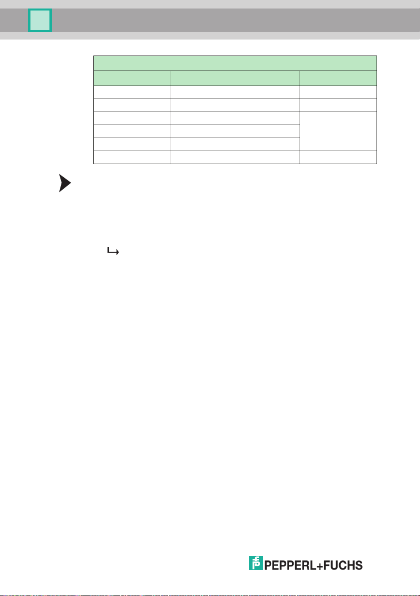
Control Word
Bit Meaning Byte
0 ... 7 Beginning of reading area 0
8 ... 15 End of read area 1
16 Password mode on / off 2
17 Mode "Read-after-Write" on / off
18 ... 23 freely usable
24 ... 31 freely usable 3
Configure read range
1. Enable the password mode (command set password mode)
2. Write into the Control Word the “beginning of the reading area” = 03h and
“end of the reading area” = 03h with the commands single write configuration
or enhanced buffered write configuration
3. Disable the password mode (command set password mode)
You can check the data area with address information reading 0000h and
word count reading 00h.
2011-08
6
Page 7
IC-KP-B6*
Communication in "IRI-B6" mode
3 Communication in "IRI-B6" mode
Only use "IRI-B6" and "IVI-B6" modes if you intend to operate the control interface
as a replacement for a control interface with the designation "IRI-KH*-4HB6" or
"IVI-KH*-4HB6".
3.1 PROFIBUS DP communication parameters (GSD file) for IRI-B6
The GSD file name for "IRI-B6" mode is: P&F_00d2.gsd.
Two modules are defined, one for input data (reading) and the other for output
data (command, transfer). The identification bytes of the modules are defined as
follows:
■ Data consistency along the entire length
■ Word structure
■ Input data ("10 Words Input" module) and output data ("1 Word Output"
module)
One word has 16 bits in "IRI-B6" mode.
The following two chapters describe the structure of the data words for
communication from the DP master to the control interface and from the control
interface to the DP master.
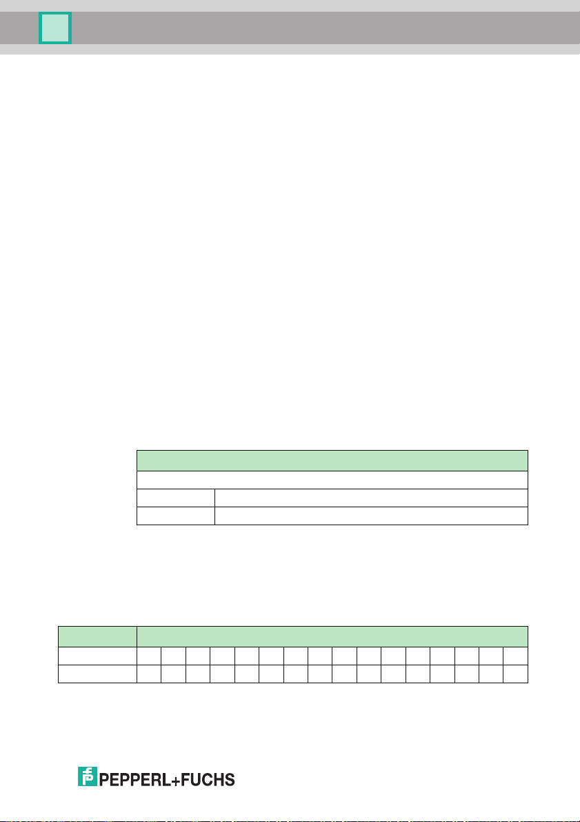
3.2 Device identification/software version message for PROFIBUS DP
The device identification and the software version are transferred via the DP
function “Device-Related Diagnostics”.
Header byte <IDENTIFIER><SW BUS>
Header byte, length of diagnostic data in bytes incl. header byte, here "13"
<IDENTIFIER> 6 characters, "IRI-B6"
<SW BUS> 6 characters, software creation date of the bus system (DDMMYY)
3.3 Communication direction: from PROFIBUS-DP to control interface
In a direction from the PROFIBUS-DP master to the control interface, the words
are structured as follows:
Word 0 Commands and parameters
Bit no. 15 14 13 12 11 10 9 8 7 6 5 4 3 2 1 0
Description B4 B3 B2 B1 DS 0 0 0 0 0 0 0 K3 K2 K1 T
The commands and command parameters are transferred in word 0.
2011-08
7
Page 8
IC-KP-B6*
Communication in "IRI-B6" mode
Toggle flag (T)
The toggle flag is used to uniquely identify a new valid command. The control
interface only accepts and executes a new command if this flag has a different
status to the previous command, i.e. when it is toggled.
When the control interface on the DP master is acknowledged, the toggle flag is
not changed and indicates to the user that the control interface has received and
processed the command.
Note!
The command is only executed if the execution counter 0.
Command identifier (B4 ... B1)
Command parameters B4 ... B1 are used to define the relevant command.
Command identifier B4 ... B1
15 14 13 12 Bit no.
B4 B3 B2 B1 Meaning
0 0 0 0 No command
0 0 0 1 SF
0 0 1 0 AF
0 0 1 1 BF
0 1 0 0 Not def.
0 1 0 1 Not def.
0 1 1 0 Not def.
0 1 1 1 Not def.
1 0 0 0 Not def.
1 0 0 1 Not def.
1 0 1 0 Not def.
1 0 1 1 Not def.
1 1 0 0 Not def.
1 1 0 1 EF
1 1 1 0 Not def.
1 1 1 1 Not def.
Double side mode (DS)
This function enables double-sided reading. If this bit is set (DS = 1), type ICC-50,
IDC-50 and IDC-CARD read only tags can be read from both sides. Otherwise
read only tags can only be read from the labeled side.
2011-08
8
Page 9

IC-KP-B6*
Communication in "IRI-B6" mode
Head number (K3 ... K1)
Parameters K3 ... K1 are used to define which reading head is addressed.
Head number K3 ... K1
3 2 1 Bit no.
K3 K2 K1 Head
0 0 0 1
0 0 1 2
0 1 0 3
0 1 1 4
1 0 0 All
1 0 1 All
1 1 0 All
1 1 1 All
3.4 Communication direction: from the control interface to the PROFIBUS-DP
In a direction from the control interface to the PROFIBUS master, the 10 data
words are structured as follows:
Word 0 Command, parameter and toggle flag mirrored
Bit no. 15 14 13 12 11 10 9 8 7 6 5 4 3 2 1 0
Description B4 B3 B2 B1 DS 0 0 0 0 0 0 0 K3 K2 K1 T
Word 1 Status/execution counter/head number
Bit no. 15 14 13 12 11 10 9 8 7 6 5 4 3 2 1 0
Description - K3 K2 K1 A4 A3 A2 A1 H4 H3 H2 H1 S4 S3 S2 S1
Word 2 ... 9 Read data
The previously sent commands and command parameters are repeated in word 0
as confirmation.
Word 1 contains status information, the execution counter and the number of the
assigned head.
Bits H4 ... H1 are only used for the EF command in “Enhanced buffered auto read
fix code” operating mode. This means:
■ H(i) = 1 head detected as connected,
■ H(i) = 0 no head connected to this channel.
Words 2 ... 9 contain the read data.
2011-08
9
Page 10

IC-KP-B6*
Communication in "IRI-B6" mode
Head number (K3 ... K1)
000b = head 1
001b = head 2
010b = head 3
011b = head 4
If "all" heads are addressed, the heads are read in succession in the sequence 1,
2, 3 and 4.
Execution counter (A4 ... A1)
The execution counter is reset when the command is executed and increases
every time new status words or data becomes available.
Note!
The fields for the head number, status and words 2 to 9 do not contain valid data if
the counter indicates 0.
Status display (S4 ... S1)
Parameters S4 ... S1 define the general status and fault messages.
Status display S4 ... S1
3 2 1 0 Bit no.
S4 S3 S2 S1 Status
0 0 0 0 Command has been executed without error
0 1 0 0 Incorrect command, invalid parameter or timeout
0 1 0 1 Read or write error
0 1 1 0 Hardware error (reading head faulty)
10
Word 2 ... 9: reading numbers/read data
A data field of 2 words is reserved for each of the four reading heads:
Word 2 / 3: Reading head 1
Word 4 / 5: Reading head 2
Word 6 / 7: Reading head 3
Word 8 / 9: Reading head 4
2011-08
Page 11

IC-KP-B6*
Communication in "IRI-B6" mode
Each data field has the following structure:
Words 2 / 4 / 6 / 8
Bit 15 14 13 12 11 10 9 8 7 6 5 4 3 2 1 0
ERR L3 L2 L1 C28 C27 C26 C25 C24 C23 C22 C21 C20 C19 C18 C17
Words 3 / 5 / 7 / 9
Bit 15 14 13 12 11 10 9 8 7 6 5 4 3 2 1 0
C16 C15 C14 C13 C12 C11 C10 C9 C8 C7 C6 C5 C4 C3 C2 C1
ERR: Read error flag, head-related
For commands SF, AF, BF: Flag is always 0.
For command EF: The read error is set when a code carrier is not located within
the detection range.
■ L3 ... 1: 3-bit reading number, head-related
The reading numbers of all active heads are set to 0 when the command is
executed and increase when the corresponding head receives data or a
status message.
In contrast, the execution counter in word 1 increases every time the
identification system sends a data or status message, irrespective of the
head number.
■ C28 ... 1: 28-bit read only code data, packed in hexadecimal format
The identification system sends the read only code as an ASCII string with
7 characters in so-called data format 10. The first three characters of the
string form a hexadecimal number and the remaining four characters form a
decimal number.
The first three characters appear directly in bits C28 to C17 following ASCII
hex conversion. The following four characters are displayed in hexadecimal
format. In order to compare them with data format 10, they must be
converted into a four-digit decimal number:
e.g.: code A764325 (ASCII): C28 ... C1 = xAh, 76h, 10h, E5 (x = ERR,
L3 ... 1).
3.5 PROFIBUS-DP command sequence
Execution of the command begins as soon as a valid command is written using
toggled flag "T". When the command is received, this flag is sent to the master
together with the remaining fields of word 0 as confirmation.
Initial state:
Head number (K3 ... 1) 0
Execution counter (N4 ... 1) 0
Stat us (S 4 . .. 1) 0
4 x read error flags (ERR) 0 for SF, AF, BF and 1 for EF
4 x reading numbers (L3 ... 1) 0
4 x read only code data (C28 ... 1) 0
2011-08
11
Page 12

IC-KP-B6*
Communication in "IRI-B6" mode
The execution counter increases every time the identification system sends a
message. At the same time, the head number, status, read error flag, reading
numbers and read only code data fields are set according to the message from
the identification system. The read error flags are treated differently, depending on
the command.
The reading numbers increase when the identification system receives read data
(status 0). Only the reading number in the data field assigned to the head number
sent by the information system is increased. The reading numbers does not
increase if the identification system reports an error (status 4, 5, 6).
The read error flag is deactivated for the SF, AF and BF commands and always
remains 0.
The following applies for the EF command: The read error flag is reset (=0) as
soon as the identification system receives some read data (status 0). The read
error flag is set as soon as the identification system reports a read error (status 5)
and remains unchanged with other fault messages (status 4, 6).
The following example shows a command sequence.
Command: Single read read only code with head 2, without double side mode
DP master sequence
Command (B4 ... B1) 0001b SF (Single read read only code)
Double side (DS) 0b Double side mode OFF
Head number (K3 ... K1) 001b Head number 2 is addressed
Toggle flag (T) 1b (or 0, depending on the previous state after
initial command or switching on = 1)
Word 0 Commands and parameters
B4 B3 B2 B1 DS 0 T2 T1 N4 N3 N2 N1 K3 K2 K1 T
0 0 0 1 0 0 0 0 0 0 0 0 0 0 1 1
= 1003hex
Response from the control interface on the DP master
Single commands are executed once and the result (success or failure) is output.
12
2011-08
Page 13

IC-KP-B6*
Communication in "IRI-B6" mode
Word 0 Word 1 Word 2 Word 3 Word 4 Wo rd 5 Word
1003
(hex)
or 1003
or 1003
Word 0: Command and parameter mirrored
Word 1: Status/execution counter/head number (see below)
Word 2 ... 9: Corresponding data from read only tag if reading successful
Word 1 Status/execution counter/head number
or 0 0 0 1 0 0 0 1 0 0 0 0 0 1 1 0
or 0 0 0 1 0 0 0 1 0 0 0 0 0 0 0 0
Head number (K3 ... K1) 001b Read with head 2
Execution counter (A4 ... A1) 0001b Executed once
Status (S4 ... S1) 0101b Read error
or 0110b Hardware error
or 0000b Command executed without error
(hex)
(hex)
1105
(hex)
1106
(hex)
1100
(hex)
- K3 K2 K1 A4 A3 A2 A1 - - - - S4 S3 S2 S1
0 0 0 1 0 0 0 1 0 0 0 0 0 1 0 1
xxxx xxxx xxxx xxxx xxxx If no read only tag in
xxxx xxxx xxxx xxxx xxxx If head not
0000
(hex)
0000
(hex)
1B54
(hex)
0E3A
(hex)
6 ... 9
0000
...
0000
(hex)
front of head
connected or
defective.
If read only tag
content "B543642"
(ASCII) in front of
head
2011-08
13
Page 14

IC-KP-B6*
Communication in "IVI-B6" mode
4 Communication in "IVI-B6" mode
Only use "IRI-B6" and "IVI-B6" modes if you intend to operate the control interface
as a replacement for a control interface with the designation "IRI-KH*-4HB6" or
"IVI-KH*-4HB6".
4.1 PROFIBUS DP communication parameters (GSD file) for IVI-B6
The GSD file name for "IVI-B6" mode is: P&F_0840.gsd.
An input module and output module are defined to transfer input data (reading,
data from slave to DP master) and output data (writing, data from DP master to
slave).
The size of the input and output modules is variable so that the transferred data
volume can be optimized for the relevant application. This prevents loading the
bus unnecessarily with unused data.
The GSD file P&F_0840.GSD is required to utilize the variable module lengths.
Input modules with lengths of 2 to 16 words and output modules with lengths of
one to 16 words are predefined in this file, each in graduations of one word.
Note!
During programming, only one input module and one output module can be
selected from the list of modules.
One word has 16 bits in "IVI-B6" mode.
The number of modules required depends on the relevant application. The output
module (i.e. the data from the DP master to the slave) consists of one or two
command data words and a maximum of 14 usable data words.
The input module (data from the slave to the DP master) always consists of two
status data words and a maximum of 14 usable data words.
Examples:
Command single/auto/buffered read fixcode:
Only one command data word and command parameter must be transferred. A
data carrier word address and write data are omitted. The module "1 Word
Output" can therefore be used here.
The length of the read only code data read by the code carrier is 4 words.
Because two status data words are always transferred in addition, the minimum
size of the input module must be 6 words, i.e. module "6 Words Input" must be
selected.
Command single/auto/buffered write, write data length e.g. 14 words:
Two words are required for the command data here (command, parameter and
data carrier word address). Together with the 14 write data words, the maximum
output module length is 16 words (16 Words Output).
For write commands, the control interface only responds with a status message
i.e. an input module size of two words is sufficient (2 Words Input).
14
2011-08
Page 15

IC-KP-B6*
Communication in "IVI-B6" mode
Command single/auto/buffered read, read data length e.g. 8 words:
Two words are required to transfer the read command (command, command
parameter and data carrier word address), i.e. module "2 Words Output" is
sufficient.
Um die gelesenen Daten und die zwei Worte Statusdaten zu übertragen, sind
insgesamt 10 Worte erforderlich, d. h. Modul "10 Words Input“ ist passend.
The following two chapters describe the structure of up to 16 data words for
communication from the DP master to the control interface and from the control
interface to the DP master.
4.2 Device identification/software version message for PROFIBUS DP
The device identification and the software version are transferred via the DP
function “Device-Related Diagnostics”.
This is structured as follows:
Byte Meaning
0 Station status 1
1 Station status 2
2 Station status 3
3 Master station number
4 Manufacturer code (high byte)
5 Manufacturer code (low byte)
from 6 Other slave-specific diagnostics (header byte, length of subsequent
7 ... 12 "IVI-B6"
13 ... 18 Software creation date of the bus system (DDMMYY)
entries)
4.3 Communication direction: from PROFIBUS-DP to control interface
The data that is transferred depends on the length of the selected output module.
Only the structure of the required words is shown in the following section. Valid
data is not allocated to any other words related to the selected module size.
Reading read only codes
Word 0 Commands and parameters
Bit no. 15 14 13 12 11 10 9 8 7 6 5 4 3 2 1 0
Description B4 B3 B2 B1 DS 0 T2 T1 N4 N3 N2 N1 K3 K2 K1 T
The commands and command parameters are transferred in word 0.
2011-08
15
Page 16

IC-KP-B6*
Communication in "IVI-B6" mode
Reading data
Word 0 Commands and parameters
Bit no. 15 14 13 12 11 10 9 8 7 6 5 4 3 2 1 0
Description B4 B3 B2 B1 DS 0 T2 T1 N4 N3 N2 N1 K3 K2 K1 T
Word 1 Word address/block addresses (for block commands SB/AB/BB)
The commands and command parameters are transferred in word 0.
Word 1 contains the start memory address of the data carrier, from which point
data is read.
Writing data
Word 0 Commands and parameters
Bit no. 15 14 13 12 11 10 9 8 7 6 5 4 3 2 1 0
Description B4 B3 B2 B1 DS 0 T2 T1 N4 N3 N2 N1 K3 K2 K1 T
Word 1 Word address/block addresses (for block commands SB/AB/BB)
Word 2 ... 15 Wri te data
16
The maximum number of words is 16 depending on the selected module size.
The commands and command parameters are transferred in word 0.
Word 1 contains the start memory address of the data carrier, from which point
data is written.
Words 2 to a maximum of 15 contain the data written for write commands.
Toggle flag (T)
The toggle flag is used to uniquely identify a new valid command. The control
interface only accepts and executes a new command if this flag has a different
status to the previous command, i.e. when it is toggled.
When the control interface on the DP master is acknowledged, the toggle flag is
not changed and indicates to the user that the control interface has received and
processed the command.
Note!
The command is only executed if the execution counter 0.
2011-08
Page 17

IC-KP-B6*
Communication in "IVI-B6" mode
Command identifier (B4 ... B1)
Command parameters B4 ... B1 are used to define the relevant command.
Command identifier B4 ... B1
15 14 13 12 Bit no.
B4 B3 B2 B1 Meaning
0 0 0 0 No command
0 0 0 1 SF
0 0 1 0 AF
0 0 1 1 BF
0 1 0 0 SR
0 1 0 1 AR
0 1 1 0 BR
0 1 1 1 SW
1 0 0 0 AW
1 0 0 1 BW
1 0 1 0 SB
1 0 1 1 AB
1 1 0 0 BB
1 1 0 1 EF
1 1 1 0 ER
1 1 1 1 EW
Double side mode (DS)
This function enables double-sided writing/reading. If this bit is set (DS = 1), type
ICC-50, IDC-50 and IDC-CARD read only and read/write tags can be read and
written from both sides. Otherwise read only and read/write tags can only be read
from the labeled side.
Note!
In double side mode, the execution time of the read/write commands increases.
2011-08
17
Page 18

IC-KP-B6*
Communication in "IVI-B6" mode
Tag type (T2, T1)
The tag type is defined by parameters T1 and T2.
Tag type T1, T2
9 8 Bit no.
T2 T1 Ty p e
0 0 IDC-1k
0 1 IPC03
1 0 IQC21
1 1 Reserved
Number of words (N4 ... N1)
Parameters N4 ... N1 define the number of words to be read or written (maximum
14 words).
Number of words N4 - N1
7 6 5 4 Bit no.
N4 N3 N2 N1 Word count
0 0 0 0 Not defined
0 0 0 1 1
0 0 1 0 2
0 0 1 1 3
0 1 0 0 4
0 1 0 1 5
0 1 1 0 6
0 1 1 1 7
1 0 0 0 8
1 0 0 1 9
1 0 1 0 10
1 0 1 1 11
1 1 0 0 12
1 1 0 1 13
1 1 1 0 14
1 1 1 1 Not defined
18
2011-08
Page 19

IC-KP-B6*
Communication in "IVI-B6" mode
Head number (K3 ... K1)
Parameters K3 ... K1 are used to define which R/W head is addressed.
Head number K3 ... K1
3 2 1 Bit no.
K3 K2 K1 Head
0 0 0 1
0 0 1 2
0 1 0 3
0 1 1 4
1 0 0 All
1 0 1 All
1 1 0 All
1 1 1 All
Word address (word 1)
The start memory address for the data to be read or written in the data carrier is
specified in this word.
Ta g t y p e
IDC-1k 0000 ... 003F 0000 ... 003F
Address range (hex)
Word addre ss ( wor d 1) Block address (SB/AB/BB)
The tag type IMC-40 is no longer supported.
4.4 Communication direction: from the control interface to the PROFIBUS-DP
The data that is transferred depends on the length of the selected input module.
Only the structure of the required words is shown in the following section. Valid
data is not allocated to any other words related to the selected module size.
Reading read only codes
Word 0 Command, parameter and toggle flag mirrored
Bit no. 15 14 13 12 11 10 9 8 7 6 5 4 3 2 1 0
Description B4 B3 B2 B1 DS 0 T2 T1 N4 N3 N2 N1 K3 K2 K1 T
Word 1 Status/execution counter/head number
Bit no. 15 14 13 12 11 10 9 8 7 6 5 4 3 2 1 0
Description - K3 K2 K1 A4 A3 A2 A1 H4 H3 H2 H1 S4 S3 S2 S1
2011-08
19
Page 20

IC-KP-B6*
Communication in "IVI-B6" mode
Word 2 ... 15 Read data
The previously sent commands and command parameters are repeated in word 0
as confirmation.
Word 1 contains status information, the execution counter and the number of the
assigned head.
Bits H4 ... H1 are only used for the EF command in Enhanced buffered read
read only code operating mode. This means:
■ H(i) = 1 head detected as connected,
■ H(i) = 0 no head connected to this channel.
Words 2 ... 15 contain the read data for read commands. With write commands,
words 2 ... 15 do not contain valid data.
Reading data
Word 0 Command, parameter and toggle flag mirrored
Bit no. 15 14 13 12 11 10 9 8 7 6 5 4 3 2 1 0
Description B4 B3 B2 B1 DS 0 T2 T1 N4 N3 N2 N1 K3 K2 K1 T
Word 1 Status/execution counter/head number
Bit no. 15 14 13 12 11 10 9 8 7 6 5 4 3 2 1 0
Description - K3 K2 K1 A4 A3 A2 A1 H4 H3 H2 H1 S4 S3 S2 S1
Word 2 ... n Read data
n is maximum of 15 depending on the selected module size.
The previously sent commands and command parameters are repeated in word 0
as confirmation.
Word 1 contains status information, the execution counter and the number of the
assigned head.
Bits H4 ... H1 are only used for the ER command in Enhanced buffered read
operating mode. This means:
■ H(i) = 1 head detected as connected,
■ H(i) = 0 no head connected to this channel.
Words 2 ... 15 contain the read data.
20
2011-08
Page 21

IC-KP-B6*
Communication in "IVI-B6" mode
Writing data
Word 0 Command, parameter and toggle flag mirrored
Bit no. 15 14 13 12 11 10 9 8 7 6 5 4 3 2 1 0
Description B4 B3 B2 B1 DS 0 T2 T1 N4 N3 N2 N1 K3 K2 K1 T
Word 1 Status/execution counter/head number
Bit no. 15 14 13 12 11 10 9 8 7 6 5 4 3 2 1 0
Description - K3 K2 K1 A4 A3 A2 A1 H4 H3 H2 H1 S4 S3 S2 S1
The previously sent commands and command parameters are repeated in word 0
as confirmation.
Word 1 contains status information, the execution counter and the number of the
assigned head.
Head number (K3 ... K1)
000b = head 1
001b = head 2
010b = head 3
011b = head 4
If "all" heads are addressed, the heads are read or written in succession in the
sequence 1, 2, 3 and 4.
Execution counter (A4 ... A1)
Note!
The execution counter is reset when the command is executed and increases
every time new status words or data becomes available. The fields for the head
number, status and words 2 to 15 do not contain valid data if the counter indicates
0.
Head activity (H4 ... H1)
Bits H4 ... H1 are only used for the EW command in Enhanced buffered write
operating mode. This means:
■ H(i) = 1 head detected as connected,
■ H(i) = 0 no head connected to this channel.
Status display (S4 ... S1)
Parameters S4 ... S1 define the general status and fault messages.
Status display S4 ... S1
3 2 1 0 Bit no.
2011-08
S4 S3 S2 S1 Status
21
Page 22

IC-KP-B6*
Communication in "IVI-B6" mode
Status display S4 ... S1
0 0 0 0 Command has been executed without error
0 1 0 0 Incorrect command, invalid parameter or timeout
0 1 0 1 Read or write error
0 1 1 0 Hardware error (reading head faulty)
4.5 PROFIBUS-DP command sequence
Execution of the command begins as soon as a valid command is written using
toggled flag "T". When the command is received, this flag is sent to the master
together with the remaining fields of word 0 as confirmation.
Initial state:
Head number (K3 ... 1) 0
Execution counter (N4 ... 1) 0
Status (S4 ... 1) 0
4 x read error flags (ERR) 0 for SF, AF, BF and 1 for EF
4 x reading numbers (L3 ... 1) 0
4 x read only code data (C28 ... 1) 0
The execution counter increases every time the identification system sends a
message. At the same time, the head number, status, read error flag, reading
numbers and read only code data fields are set according to the message from
the identification system. The read error flags are treated differently, depending on
the command.
The reading numbers increase when the identification system receives read data
(status 0). Only the reading number in the data field assigned to the head number
sent by the information system is increased. The reading numbers does not
increase if the identification system reports an error (status 4, 5, 6).
The read error flag is deactivated for the SF, AF and BF commands and always
remains 0.
The following applies for the EF command: The read error flag is reset (=0) as
soon as the identification system receives some read data (status 0). The read
error flag is set as soon as the identification system reports a read error (status 5)
and remains unchanged with other fault messages (status 4, 6).
The following example shows a command sequence.
22
2011-08
Page 23

IC-KP-B6*
Communication in "IVI-B6" mode
Command: Single read read only code with head 2, without double side mode
DP master sequence
Command (B4 ... B1) 0001b SF (Single read read only code)
Double side (DS) 0b Double side mode OFF
Tag type (T2, T1) 00b IDC-1k
Number of words
(N4 ... N1)
Head number
(K3 ... K1)
Toggle flag (T) 1b (or 0, depending on the previous state after initial
Word 0 Commands and parameters
B4 B3 B2 B1 DS 0 T2 T1 N4 N3 N2 N1 K3 K2 K1 T
0 0 0 1 0 0 0 0 0 1 0 0 0 0 1 1
Table 4.1 = 1043hex
Note!
Words 1 ... 15 do not contain valid data. However, this only applies for read only
codes. In the case of read/write tags, word 1 would contain the start memory
address and words 2 ... 15 (for write commands) the data to be written.
0100b 4 words = 8 bytes (because read only code
001b Head number 2 is addressed
consists of 7 bytes, the 8th byte has no meaning)
command or switching on = 1)
Response from the control interface on the DP master
Singlecommands are executed once and the result (success or failure) is output.
Word 0 Word 1 Word 2 Word 3 Word 4 Word 5
1043
(hex)
or 1043
or 1043
Word 0: Command and parameter mirrored
Word 1: Status/execution counter/head number (see below)
Word 2 ... 5: If reading is successful, the corresponding data of the read only tag appears here.
Word 6 ... 15: No valid data
2011-08
(hex)
(hex)
1105
(hex)
1106
(hex)
1100
(hex)
xxxx xxxx xxxx xxxx If no read only tag in
xxxx xxxx xxxx xxxx If head not
4235
(hex)
3433
(hex)
3634
(hex)
32xx
(hex)
front of head
connected or
defective.
If read only tag
content "B543642"
(ASCII) in front of
head
23
Page 24

IC-KP-B6*
Communication in "IVI-B6" mode
Word 1 Status/execution counter/head number
- K3 K2 K1 A4 A3 A2 A1 - - - - S4 S3 S2 S1
0 0 0 1 0 0 0 1 0 0 0 0 0 1 0 1
or 0 0 0 1 0 0 0 1 0 0 0 0 0 1 1 0
or 0 0 0 1 0 0 0 1 0 0 0 0 0 0 0 0
Head number (K3 ... K1) 001b Read with head 2
Execution counter (A4 ... A1) 0001b Executed once
Status (S4 ... S1) 0101b Read or write error
or 0110b Hardware error
or 0000b Command executed without error
24
2011-08
Page 25

IC-KP-B6*
ASCII table
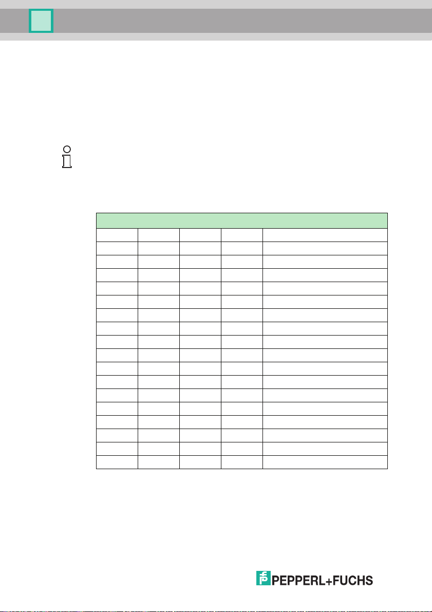
5ASCII table
hex dec ASCII hex dec ASCII hex dec
00 0 NUL 20 32 Space 40 64 @ 60 96 '
01 1 SOH 21 33 ! 41 65 A 61 97 a
02 2 STX 22 34 " 42 66 B 62 98 b
03 3 ETX 23 35 # 43 67 C 63 99 c
04 4 EOT 24 36 $ 44 68 D 64 100 d
05 5 ENQ 25 37 % 45 69 E 65 101 e
06 6 ACK 26 38 & 46 70 F 66 102 f
07 7 BEL 27 39 ' 47 71 G 67 103 g
08 8 BS 28 40 ( 48 72 H 68 104 h
09 9 HT 29 41 ) 49 73 I 69 105 I
0A 10 LF 2A 42 * 4A 74 J 6A 106 j
0B 11 VT 2B 43 + 4B 75 K 6B 107 k
0C 12 FF 2C 44 , 4C 76 L 6C 108 l
0D 13 CR 2D 45 - 4D 77 M 6D 109 m
0E 14 SO 2E 46 . 4E 78 N 6E 110 n
0F 15 SI 2F 47 / 4F 79 O 6F 111 o
10 16 DLE 30 48 0 50 80 P 70 112 p
11 17 DC1 31 49 1 51 81 Q 71 113 q
12 18 DC2 32 50 2 52 82 R 72 114 r
13 19 DC3 33 51 3 53 83 S 73 115 s
14 20 DC4 34 52 4 54 84 T 74 116 t
15 21 NAK 35 53 5 55 85 U 75 117 u
16 22 SYN 36 54 6 56 86 V 76 118 v
17 23 ETB 37 55 7 57 87 W 77 119 w
18 24 CAN 38 56 8 58 88 X 78 120 x
19 25 EM 39 57 9 59 89 Y 79 121 y
1A 26 SUB 3A 58 : 5A 90 Z 7A 122 z
1B 27 ESC 3B 59 ; 5B 91 [ 7B 123 {
1C 28 FS 3C 60 < 5C 92 \ 7C 124 |
1D 29 GS 3D 61 = 5D 93 ] 7D 125 }
1E 30 RS 3E 62 > 5E 94 ^ 7E 126 ~
1F 31 US 3F 63 ? 5F 95 _ 7F 127 DEL
ASCI
hex dec ASCII
I
2011-08
25
Page 26

Subject to modifications
Copyright PEPPERL+FUCHS • Printed in Germany
www.pepperl-fuchs.com
Worldwide Headquarters
Pepperl+Fuchs GmbH
68307 Mannheim · Germany
Tel. +49 621 776-0
E-mail: info@de.pepperl-fuchs.com
USA Headquarters
Pepperl+Fuchs Inc.
Twinsburg, Ohio 44087 · USA
Tel. +1 330 4253555
E-mail: sales@us.pepperl-fuchs.com
Asia Pacific Headquarters
Pepperl+Fuchs Pte Ltd.
Company Registration No. 199003130E
Singapore 139942
Tel. +65 67799091
E-mail: sales@sg.pepperl-fuchs.com
FACTORY AUTOMATION –
SENSING YOUR NEEDS
TDOCT2491A_ENG
08/2011
 Loading...