

Page 1
FACTORY AUTOMATION
MANUAL
IC-KP-R2-V1
IDENTControl interface
with serial interface
Page 2

IC-KP-R2-V1
With regard to the supply of products, the current issue of the following document is ap-
plicable: The General Terms of Delivery for Products and Services of the Electrical Indus-
try, published by the Central Association of the Electrical Industry (Zentralverband
Elektrotechnik und Elektroindustrie (ZVEI) e.V.) in its most recent version as well as the
supplementary clause: "Expanded reservation of proprietorship"
Page 3

IC-KP-R2-V1
1 Introduction................................................................................. 5
2 Declaration of conformity .......................................................... 6
2.1 Declaration of conformity.................................................................... 6
3 Safety........................................................................................... 7
3.1 Symbols relevant to safety.................................................................. 7
3.2 Intended use......................................................................................... 7
3.3 General notes on safety ....................................................................... 7
3.4 Contact protection ............................................................................... 8
4 Product Description ................................................................... 9
4.1 Range of application............................................................................ 9
4.2 Device characteristics ......................................................................... 9
4.3 Product family ...................................................................................... 9
4.3.1 R/W heads......................................................................................... 9
4.3.2 Code / Data carrier............................................................................. 9
4.3.3 Handhelds....................................................................................... 10
4.4 Displays and controls........................................................................ 10
4.5 Interfaces and connections .............................................................. 11
4.6 Delivery package................................................................................ 11
4.7 Connection accessories.................................................................... 12
4.7.1 Connection cable for R/W heads and trigger sensors...................... 12
4.7.2 Cable connectors for the power supply............................................ 12
4.7.3 Connection cable to the serial interface ........................................... 13
5 Installation................................................................................. 14
5.1 Storage and transport........................................................................ 14
5.2 Unpacking........................................................................................... 14
5.3 EMC concept ...................................................................................... 14
3
Page 4

IC-KP-R2-V1
5.4 Device connection..............................................................................15
5.4.1 Power supply....................................................................................15
5.4.2 Read/Write Head and Trigger Sensors.............................................15
5.4.3 Cable length between control interface and R/W heads...................16
5.4.4 Ground connection........................................................................... 16
5.4.5 Instructions for connecting the command interface .......................... 16
6 Commissioning......................................................................... 18
6.1 Commissioning...................................................................................18
6.1.1 Connection.......................................................................................18
6.1.2 Device settings .................................................................................18
6.1.3 Output of the contents of read data carriers on the display ...............19
6.1.4 Operating with the communication interface.....................................20
7 Commands ................................................................................ 22
7.1 General information on the serial interface......................................22
7.1.1 Command examples ........................................................................22
7.2 Command types .................................................................................24
7.3 Command overview............................................................................24
7.3.1 System commands...........................................................................26
7.3.2 Standard read/write commands........................................................31
7.3.3 Special command modes.................................................................33
7.4 Legend.................................................................................................42
7.5 Fault/status messages .......................................................................43
8 Technical Specifications .......................................................... 44
8.1 Dimensions .........................................................................................44
8.2 General data ........................................................................................44
9 Troubleshooting........................................................................ 46
9.1 Fault location ......................................................................................46
10 ASCII table................................................................................. 47
4
Page 5

IC-KP-R2-V1
Introduction
1Introduction
Congratulations
You have chosen a device manufactured by Pepperl+Fuchs. Pepperl+Fuchs develops,
produces and distributes electronic sensors and interface modules for the market of
automation technology on a worldwide scale.
Before installing this equipment and put into operation, read this manual carefully. This manual
con tain es instructions and notes to help you through the installation and commiss ioning s tep
by step. This makes sure bring such a trouble-free use of this product. This is for your benefit,
since this:
■
ensures the safe ope rati o n of th e device
■
helps you to exploit the full functionality of the device
■
avoids errors and related malfunctions
■
avoids costs by disruptions and any repairs
■
increases the effectiveness and efficiency of your plant
Keep this manual at hand for subsequent operations on the device.
After opening the packaging please check the integrity of the device and the number of pieces
of supplied.
Symbols used
The following symbols are used in this manual:
Note!
This symbol draws your attention to important information.
Handling instructions
You will find handling instructions beside this symbol
Contact
If you have any questions about the device, its functions, or accessories, please contact us at:
Pepperl+Fuchs GmbH
Lilienthalstraße 200
68307 Mannheim
Telephone: +49 621 776-4411
Fax: +49 621 776-274411
E-M a il: fa-info@pepperl-fuchs.co m
2014-03
5
Page 6

IC-KP-R2-V1
Declaration of conformity
2 Declaration of conformity
2.1 Declaration of conformity
This product was developed and manufactured under observance of the applicable European
standards and guidelines.
Note!
A Declaration of Conformity can be requested from the manufacturer.
The product manufacturer, Pepperl+Fuchs GmbH, D-68307 Mannheim, has a certified quality
assurance system that conforms to ISO 9001.
ISO9001
2014-03
6
Page 7

IC-KP-R2-V1
Safety
3Safety
3.1 Symbols relevant to safety
Danger!
This symbol indicates an imminent danger.
Non-observance will result in personal injury or death.
Warning!
This symbol indicates a possible fault or danger.
Non-observance may cause personal injury or serious property damage.
Caution!
This symbol indicates a possible fault.
Non-observance could interrupt devices and any connected facilities or systems, or result in
their c o mplete failure.
3.2 Intended use
The IDENTControl IC-KP-R2-V1 is a control interface including a serial interface for
identification systems. The device can be used as a control cabinet module or for field
applications. Besides the serial connection, suitable inductive R/W heads, microwave
antennas or trigger sensors can be connected. Wiring suitable for the system design m ust be
used.
3.3 General notes on safety
Only instructed specialist staff may operate the device in accordance with the operating
manual.
User modification and or repair are dangerou s and will void the warranty and exclude the
manufacturer from any liability. If serious faults occur, stop using the device. Secure the device
against inadvertent operation. In the event of repairs, return the device to your local
Pepperl+Fuchs representative or sales office.
The connection of the device and maintenance work when live may only be carried out by a
qualified electrical specialist.
The operating company bears responsibility for observing locally applicable safety regulations.
Store the not used device in the original packaging. This offers the device optimal protection
against impact and moisture.
Ensure that the ambient conditions comply with regulations.
Note!
Disposal
Electronic waste is hazardous waste. When disposing of the equipment, observe the current
statutory requirements in the respective country of use, as well as local regulations.
2014-03
7
Page 8
IC-KP-R2-V1
Read head IDENTControl
Compact
Safety
3.4 Contact protection
Ou r ho usings are man ufactured usi n g co mpon ents made partly or c o mpletely from me tal to
improve noise immunity.
Danger!
Electric shock
The metallic housing components are connected to ground to protect against dangerous
voltages that may occur in the event of a fault in the SELV power supply!
8
2014-03
Page 9

IC-KP-R2-V1
Product Description
4Product Description
4.1 Range of application
The system is suited for the following applications:
■
Automation
■
Material flow control in production
■
Acquisition of o perating data
■
Access control
■
Identification of storage vessels, pallets, work piece carriers, refuse containers, tanks,
containers, etc.
4.2 Device characteristics
■
Up to 4 R/W heads can be connected
■
Alternatively up to 2 R/W heads and 2 trigger sensors can be connected
■
LCD indic ator with backg roun d illumination
■
Direct operation using 4 function keys
■
LED s tatus indicator for bus commun ication and R/W heads
4.3 Product family
The IDENTControl brand name represents a complete identification system. The system
consists of an IDENTControl interface including bus interface, inductive R/W heads (125 kHz
and 13.56 MHz) and accompanying code and data carriers in many different designs. The
IDENTControl can be connected to other identification systems.
The system is equally well suited for use in the switching cabinet and for field use in IP67. The
interface to the controlling fieldbus is integrated into the enclosure and all connections are
implemented as plugs. This enables simple installation and quick, correct replacement in case
of device failure. The consistent EMC design (metal enclosure, grounding, shielded wires)
offers a high degree of noise immunity. Function buttons are available for parameterization and
entering commands directly into the IDENTControl.
4.3.1 R/W heads
There are different R/W heads available for the IDENTControl in different designs. You can
connect inductive R/W heads (125 kHz and 13.56 MHz) depending on your particular
application.
4.3.2 Code / Data carrier
Read only / read/write tag 125 kHz (inductive)
A wide range of read only and read/write tag designs are available for this frequency range,
from a 3 mm thin glass tube to a transponder 50 mm in diameter. Read/write tags are available
for te mperatures up to 300 °C (max. 5 min) in che mical-resistant hous ings for installation in
metal and in degree of protection IP68/IP69K. IPC02-... read only tags offer 40-bit read only
codes. IPC03-... read/write tags have a 928-bit freely programmable memory bank and an
unmodifiable 32-bit read only code. You can define 40-bit read only codes with IPC11-... read
only tags. You can use these as permanent read only codes or continually redefine them.
Read/write tag 13.56 MHz (inductive)
Read/write tag s in th is fre quency ran ge save larger qua nti ties o f data and offer a considera bly
higher reading speed than read/write tags of the 125 kHz system. IQH-* and IQH1-* read/write
heads from Pepperl+Fuchs are compatible with most ex is ti ng read/write tags th at comply with
standard ISO 15693. With the IQH2-* read/write heads you can use read/write tags that comply
with standard ISO 14443A.
2014-03
9
Page 10
IC-KP-R2-V1
Product Description
The 13.56 MHz technology even allows smart labels (read/write tags in the form of adhesive
labels with printed barcode). Currently available read/write tags have a memory capacity of
64 bits of read only code and a maximum 2 KB of programmable memory.
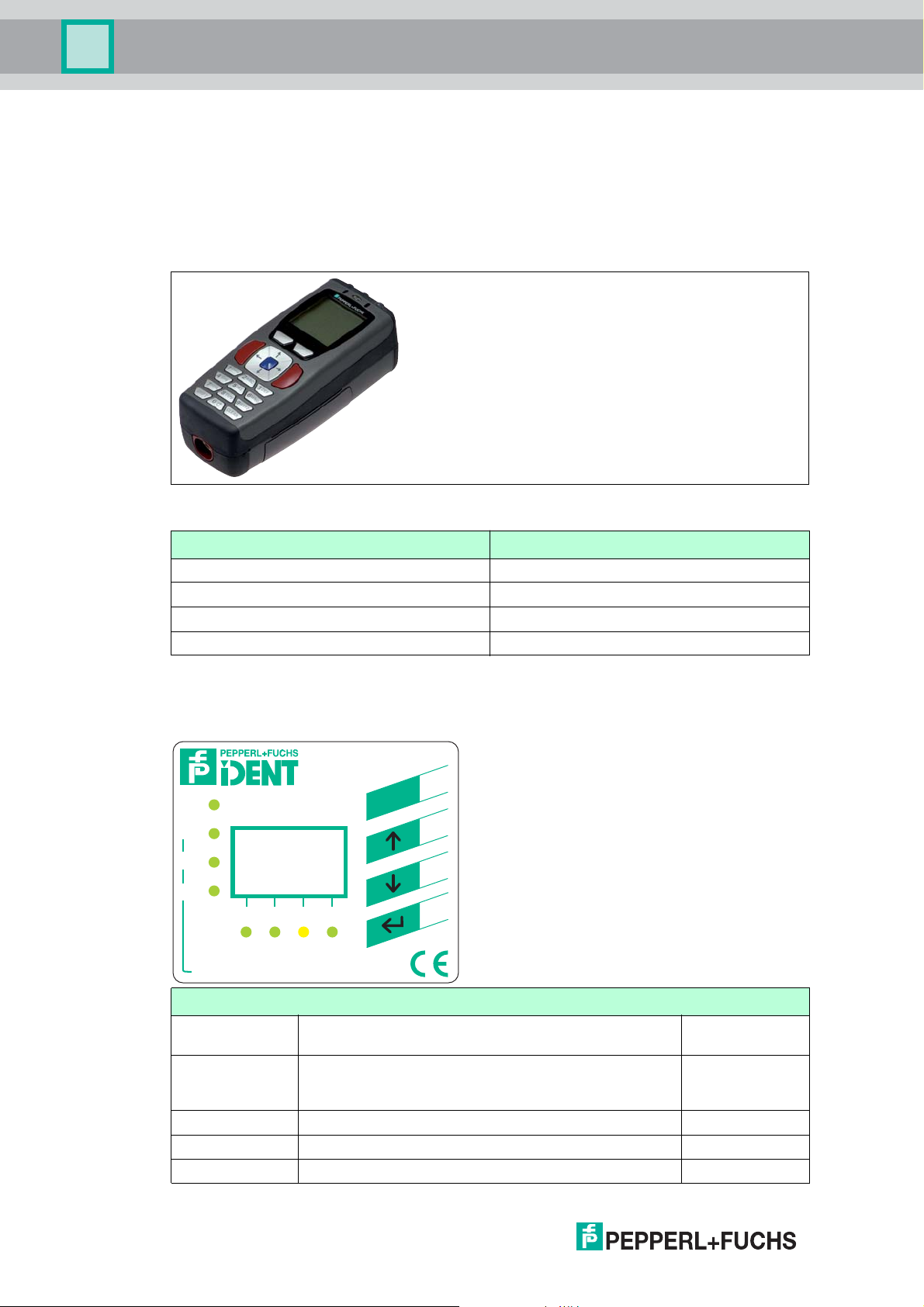
4.3.3 Handhelds
There are various handheld read/write devices available for controlling proces ses (write/read
functions, initialization of data carriers).
Figure 4.1
Handheld Frequency range
IPT-HH20 125 kHz
IST-HH 20 250 kHz
IQT1-HH20 13.56 MHz
IC-HH20-V1 depending on the read/write head
4.4 Displays and controls
The following displays and controls are located on the control interface.
PWR/
ERR
UL
Tx D
RxD
IC-KP-R.-...
Part No.
1
234
C
S
E
10
Serial
LED indicators
PWR/ERR Power on
Ha rdware error
1, 2, 3, 4 Status display for R/W heads
Command on R/W head is active
Command executed successfully (approx. 1 second)
UL Interface ready for operation green
TxD IDENTControl sends data green
RxD IDENTControl receives data green
green
red
green
yellow
2014-03
Page 11
IC-KP-R2-V1
Product Description
Display
Two-line multifunction display with 12 characters per line for displaying different status and
operating information and four pictograms for displaying connected reading heads.
Push buttons
Push buttons are used for controlling the display and selecting commands when programming
the control interface.
ESC
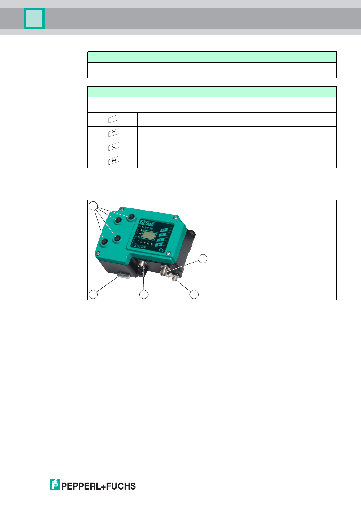
4.5 Interfaces and connections
Return to higher level
Up menu item
Down menu item
RETURN (confirm input)
The following interfaces and connections are located on the control interface IC-KP-R2-V1.
1
2
3B A
Connections
1 M12 connector for R/W heads (sockets) - V1
2 M12 connector for power supply (plug) - V1
3 M12 socket for serial interface - V1
Other accessories
A Screw for ground
B Metal latches for mounting the DIN rail
Accessories
Accessories see chapter 4.7.
4.6 Delivery package
The delivery package contains:
■
1 IDENTControl control interface
■
1 quick start guide
■
1 grounding screw (already fitted)
■
1 serrated lock washer (already fitted)
2014-03
■
2 crimp connectors (already fitted)
11
Page 12
IC-KP-R2-V1
Product Description
4.7 Connection accessories
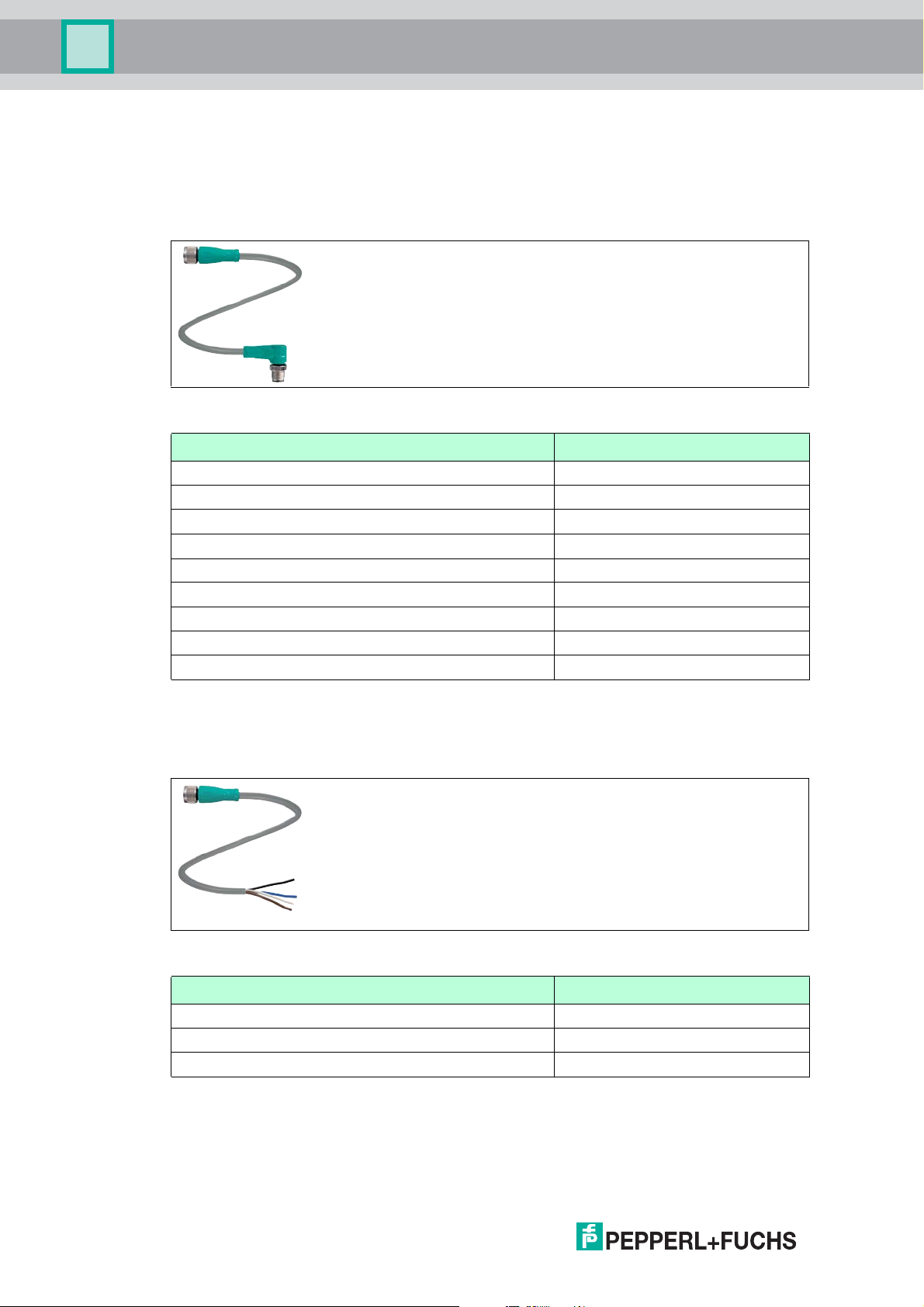
4.7.1 Connection cable for R/W heads and trigger sensors
Compatible connection cables with shielding are available for connecting the R/W heads and
trigger sensors.
Figure 4.2
Accessories Description
2 m long (straight female, angled male) V1-G-2M-PUR-ABG-V1-W
5 m long (straight female, angled male) V1-G-5M-PUR-ABG-V1-W
10 m long (straight female, angled male) V1-G-10M-PUR-ABG-V1-W
20 m long (straight female, angled male) V1-G-20M-PUR-ABG-V1-W
Field attachable fema le c on nector, straig ht, shielded V1-G-ABG-PG9
Field attachable male connector, straight, sh ielded V1S-G-ABG-PG9
Field attachable fema le c on nector, angled, shielded V1-W-ABG-PG9
Field attachable male connector, angled, shielded V1S-W-ABG-PG9
Dummy plug M12x1 VAZ-V1-B3
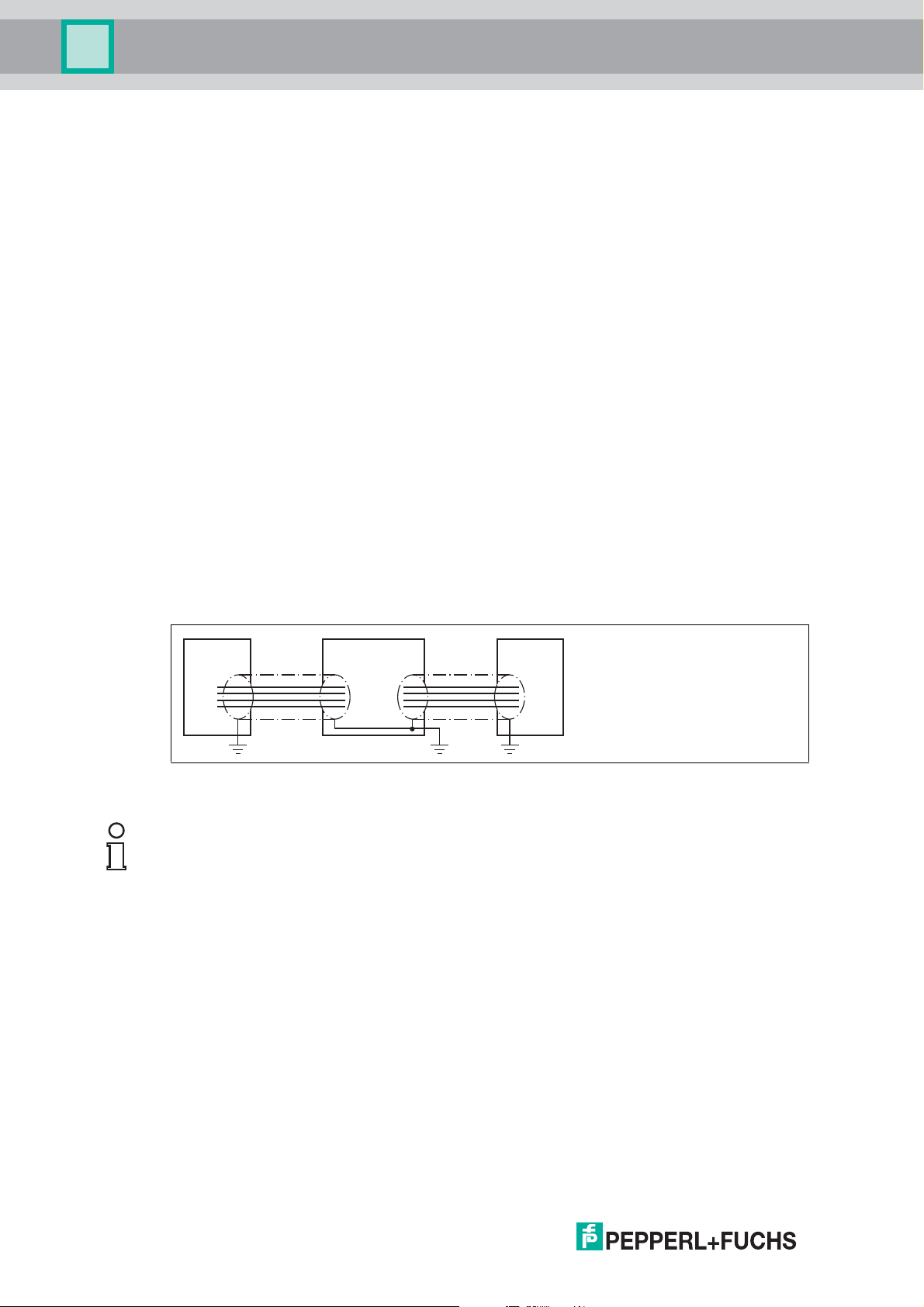
4.7.2 Cable connectors for the power supply
Compatible M12 sockets with an open cable end for connecting the IDENTControl to a power
supply are availa ble in different lengths.
Figure 4.3
Accessories Designation
Length 2 m (straight socket) V1-G-2M-PUR
Length 5 m (straight socket) V1-G-5M-PUR
Length 10 m (straight socket) V1-G-10M-PUR
12
2014-03
Page 13

IC-KP-R2-V1
Product Description
4.7.3 Connection cable to the serial interface
The IDENT Control IC-KP-R2-V1 has an M12 connector and is connected to the host using a
suitable c able .
Figure 4.4
Accessories Designation
M12 cable connector, shielded, field-attachable V1S-G-ABG-PG9
Adapter cable, M12 to Sub-D (for connection to a PC
using a nu ll modem cable )
Null modem cable Sub-D IVZ-K-R2
V1S-G-0.15M-PUR-ABG-SUBD
2014-03
13
Page 14
IC-KP-R2-V1
Read head PLCIDENTControl
RS 232
Installation
5 Installation
5.1 Storage and transport
For storage and transport purposes, package the unit using s hockproof packaging material
and protect it against moisture. The best method of protection is to package the unit using the
original packaging. Furthermore, ensure that the ambient conditions are within allowable range.
5.2 Unpacking
Check the product for damage while unpacking. In the event of damage to the product, inform
the post office or parcel service and notify the supplier.
Check the package contents with your purchase order and the shipping documents for:
■
Delivery quantity
■
Device type and version in accordance with the type plate
■
Accessories
■
Quick start guide
Retain the original packaging in case you have to store or ship the device again at a later date.
Should you have any questions, please contact Pepperl+Fuchs.
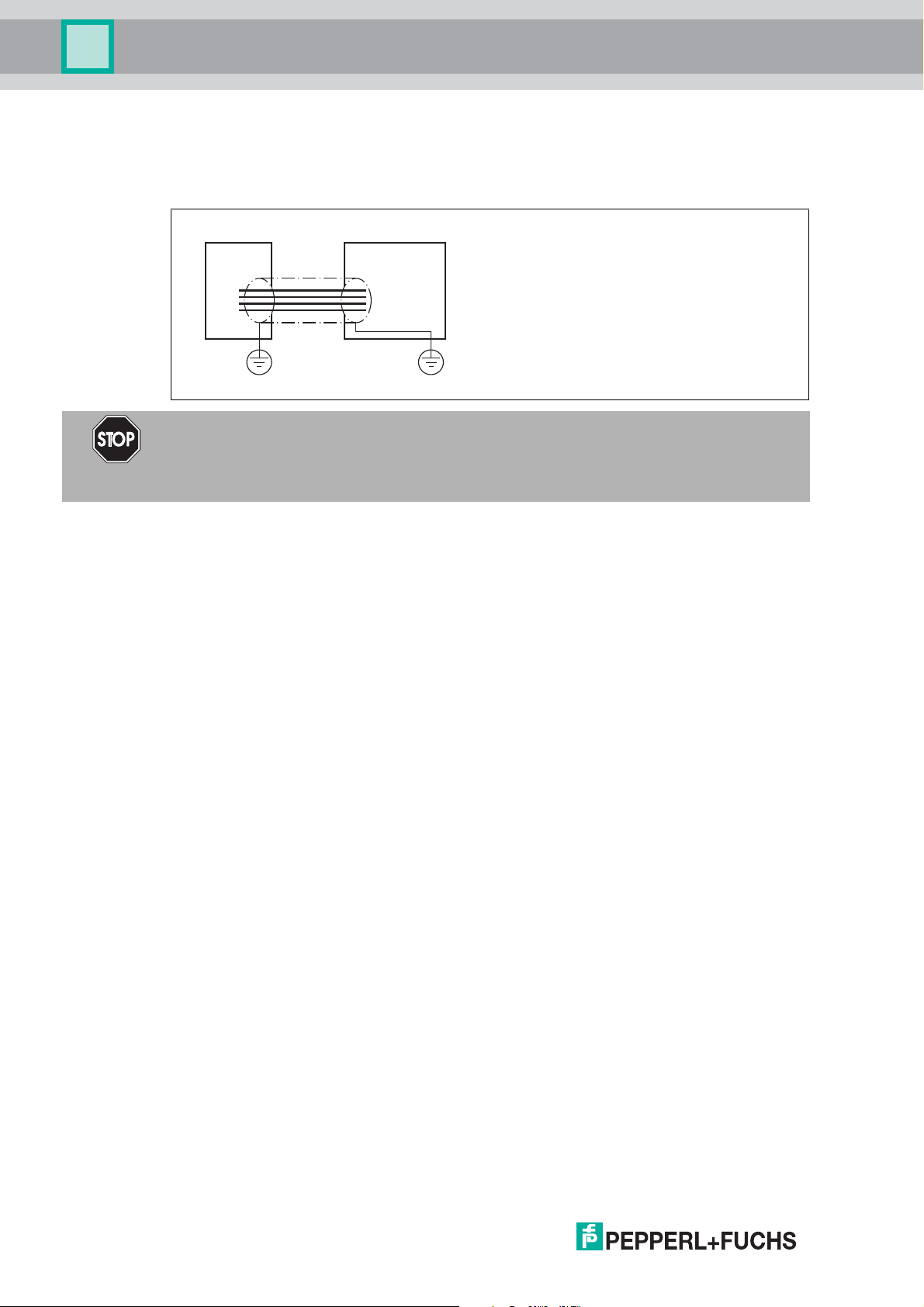
5.3 EMC concept
The outstanding noise immunity of the IDENTControl against emission and immission is based
on its consistent shielding design, which uses the principle of the Faraday cage. Interference is
caught in th e sh ie ld and sa fely diverted via the ground c onn ections.
The cable shielding is used to discharge electromagnetic interference. Wh en shielding a cable,
you must connect both sides of the shield to ground with low resistance and low inductance.
Note!
If cables with double shields are used, e.g. wire mesh and metalized foil, the both shields must
be connected together, with low resistance, at the ends when making up the cable.
Power supply cables are the source of much interference, e.g. from the supply lines of 3-phase
electric motors. For this reason, the parallel laying of power supply cables with data and signal
cables should be avoided, particularly in the same cable duct.
The metal enclosure of the IDENTControl and the metal enclosure of the R/W heads complete
the consistent shielding concept.
The most important issue here is that the shields are connected to ground with low resistance
and low inductance. The metal enclosure ensures that the shielding is not interrupted, i.e. the
complete electronics system and all routed cables are located within a Faraday cage.
14
2014-03
Page 15

IC-KP-R2-V1
4
13
2
trigger switch
trigger sensor
read/write head
signal
socket at housing
2
13
4
5
+
A
-
+
-
B
1
2
3
4
5
Installation
5.4 Device connection
Electrical connection using plug connectors makes installation simple.
5.4.1 Power supply
Connect the power supply via an M12 connector with integrated voltage and reverse polarity
protection indicator (green: correct polarity, red: reverse polarity). A plug with the following pin
assignment is located on the housing:
1 + 24 V
2 NC
3 GND
4 NC
Power supply AIDA
Connect the power supply for the IDENTControl using a connector that conforms with AIDA. A
plug with the following pin assignment is located on the housing:
12345
1 + 24 V
2 GND
3 n.c.
4 n.c.
5 n.c.
Compatible connecting cable see chapter 4.7.2.
5.4.2 Read/Write Head and Trigger Sensors
A maximum of 4 read/write heads can be connected to the IDENTControl.
Instead of the read/write heads, a maximum of 2 trigger sensors can be connected to sockets 3
and 4. A trigger sensor can be assigned to only one read/write head. The trigger sensors must
be PNP.
2014-03
Connect the read/write heads and trigger sensors to the sockets on the top of the enclosure
using M12 connectors.
For details of compatible read/write heads and of com patible connecting cables, see chapter
4.7.1.
15
Page 16

IC-KP-R2-V1
12 43
1
4
2
3
Installation
5.4.3 Cable length between control interface and R/W heads
The maximum cable length between the control interface and a connected R/W head is 1000
meters. If you wis h to attain the m aximum po ssible ca ble length, select a suitably large ca ble
cross-section. See chapter 4.7.1
5.4.4 Ground connection
The ground conne ction of the IDEN TControl is located at the lower right of the connector array.
The ground conductor is screwed to the housing with a crimp connector. In order to guarantee
safe grounding, the serrated washer must be mounted between the crimp connector and the
housing.
1 Housing
2 Serrated lock washer
3 Crimp connector
4 Lock screw
A cross-section of at least 4 mm2 is recommended for the ground con duc tor lea d.
5.4.5 Instructions for connecting the command interface
The IDENTControl is fitted with serial interface RS 232.
Select the transfer rate (baud rate) using the software or the display.
The following transfer rates are available:
■
1200, 2400, 4800, 9600, 19200, 38400 bits/s
The status is preset at 9600 Mbit/s on delivery.
The device operates with the following parameters (permanent):
■
8 data bits
■
1 start bit
■
1 stop bit
■
No parity
Connect the RS 232 interface via a 4-pin M12 socket. You must place the cable shield on the
thread in the connector plug.
16
Pin assignment of the M12 socket for RS 232
1 NC
2 RxD
3 GND
4 TxD
2014-03
Page 17

IC-KP-R2-V1
Installation
RxD
TxD
GND
Host-PC
RxD
TxD
GND
1
2
4
3
IC-KP-R2-V1
Transfer rates, line lengths and line types
The maximum length of the cable between the control unit and the higher level computer
depends on the transfer rate and the noise level. We recommend the following guide value:
Stand ard Max cable length
RS232 15 m
2014-03
17
Page 18

IC-KP-R2-V1
Commissioning
6 Commissioning
6.1 Commissioning
6.1.1 Connection
Warning!
Before commissioning, check once again that the connections are correct.
After the supply voltage is connected, the green LED in the voltage connector and the PWR
and UL LEDs on the display panel must light up. If the LED in the connector lights up red, the
polarity of the power supply is reversed.
6.1.2 Device settings
Warning!
Device not configured or configured incorrectly
Configure the device prior to commissioning. A device that has not been configured or
configured incorrectly may lead to faults in the plant.
You must set the various parameters prior to comm issioning.
The parameters are volatile and non-volatile parameters. Volatile parameters are reset to their
default setting when the system is switched off and on again.
Non-volatile parameters
Parameter Default setting Value range
Ge n e r a l
LCD contrast 50 36 ... 71
LCD ligh t On On / off
Language English English / German
Multiplex mode off On / off
R/W head
Trigger mode off On / off
Tag ty p e 99 00 ... FF
RS 232 interface
Baud rate 9600 1200, 2400, 4800, 9600,
19200, 38400
Timeout 0 0 ... 100
Volatile parameters
Parameter Default setting Value range
R/W head
Password mode Off on / off
Password 00000000 00000000 ... FFFFFFFF
18
Configure the read/write station with the described system commands. "99" is preset as the tag
type.
2014-03
Page 19

IC-KP-R2-V1
Versionsinformation
IPH1 IPH2 IPH3 IPH4
IDENTControl...
IPH1 IPH2 IPH3 IPH4
IdentControl
Einstellung
IPH1 IPH2 IPH3 IPH4
Konfigstatus
IdentControl
IPH1 IPH2 IPH3 IPH4
MultiplexM.
X
IPH1 IPH2 IPH3 IPH4
TagTyp
XX XX XX XX
IPH1 IPH2 IPH3 IPH4
TriggerMode
XXX
IPH1 IPH2 IPH3 IPH4
TriggerState
H3:X H4:X
IPH1 IPH2 IPH3 IPH4
IdentGateway
IC-KP-R..
IPH1 IPH2 IPH3 IPH4
Default
Einstellung
IPH1 IPH2 IPH3 IPH4
Konfiguriere
Kanäle
IPH1 IPH2 IPH3 IPH4
Aktiviere
Befehl
IPH1 IPH2 IPH3 IPH4
Datenträger
einstellen
IPH1 IPH2 IPH3 IPH4
Version
KanalNr:
IPH1 IPH2 IPH3 IPH4
IDENT
Gateway...
IPH1 IPH2 IPH3 IPH4
EnhancedRead
Fixcode
IPH1 IPH2 IPH3 IPH4
KanalNr: X
IPH1 IPH2 IPH3 IPH4
Enhanced
Read 1 Wort
IPH1 IPH2 IPH3 IPH4
KanalNr: X
IPH1 IPH2 IPH3 IPH4
Triggermode
...
IPH1 IPH2 IPH3 IPH4
Sensorkanal
-> X
IPH1 IPH2 IPH3 IPH4
Befehl
abbrechen
IPH1 IPH2 IPH3 IPH4
KanalNr: X
IPH1 IPH2 IPH3 IPH4
Reset
Identcontrol
IPH1 IPH2 IPH3 IPH4
Wort-Adresse
XXXX
IPH1 IPH2 IPH3 IPH4
Display
einstellen..
IPH1 IPH2 IPH3 IPH4
Sprache
einstellen
IPH1 IPH2 IPH3 IPH4
Konfiguriere
Seriell
IPH1 IPH2 IPH3 IPH4
BUS Adresse
XX
IPH1 IPH2 IPH3 IPH4
LCD-Licht
ein/aus
IPH1 IPH2 IPH3 IPH4
LCD-Kontrast
einstellen
IPH1 IPH2 IPH3 IPH4
Default
Einstellung
IPH1 IPH2 IPH3 IPH4
Sprache
Deutsch
IPH1 IPH2 IPH3 IPH4
LCD-Kontrast
XX
IPH1 IPH2 IPH3 IPH4
KanalNr: X
IPH1 IPH2 IPH3 IPH4
KanalNr: X
IPH1 IPH2 IPH3 IPH4
Datenträger:
XX
IPH1 IPH2 IPH3 IPH4
IXH-XXXX
XX.XX.XX
IPH1 IPH2 IPH3 IPH4
Multiplexed
XXX
IPH1 IPH2 IPH3 IPH4
Multiplexed
Mode...
IPH1 IPH2 IPH3 IPH4
Setze
Defaultwerte
IPH1 IPH2 IPH3 IPH4
Identkanal
-> X
IPH1 IPH2 IPH3 IPH4
Triggermode
XXX
IPH1 IPH2 IPH3 IPH4
Tastendruck auf
ESC
Tastendruck auf
Tastendruck auf
Tastendruck auf
Richtung
Richtung
Richtung
Richtung
Restart?
X
IPH1 IPH2 IPH3 IPH4
BUS Address
XX
IPH1 IPH2 IPH3 IPH4
Baudrate
X
IPH1 IPH2 IPH3 IPH4
Timeout
100ms x XXX
IPH1 IPH2 IPH3 IPH4
Neustart?
X
IPH1 IPH2 IPH3 IPH4
Commissioning
Operating the device
The following illustration shows how the device is operated directly:
6.1.3 Output of the contents of read data carriers on the display
2014-03
In the first menu level, the IDENTControl shows the contents of read data carriers on the
display. Information messages of this kind are marked with a bell icon ( ) in the top right corner
of the display to distinguish them from menu items.
A maxi mum of the first 12 ch aracters of the read data set can be displayed. The following
characters may be excluded.
The view on the display can be toggled by pressing the arrow buttons. The following display
variants are available:
19
Page 20

IC-KP-R2-V1
Commissioning
■
HEX (hexadecimal with decimal delimiter)
■
HEX2 (hexadecimal without decimal delimiter)
■
ASCII (ASC)
Note!
Data carrier content from commands that are activated manually on the IDENTControl are
always displayed, irrespective of the menu level that was just displayed.
6.1.4 Operating with the communication interface
The procedure for commissioning the IDENTControl IC-KP-R2-V1 using the serial RS 232
interface in conjunction with a PC and an IPC03 data carrier is described in the following
section. It is assumed that the IDENTControl is in factory default condition when all of the
following steps are performed.
The factory set transfer rate is 9600 baud and no timeout. '99' is the preset tag type (depending
on the reading head).
Check that you have connected an RS 232 interface.
The transfer rate (baud rate ) is se lected using the softwa re (se e ch apter 5.4 .5 ).
The following transfer rates are available:
■
1200, 2400, 4800, 9600, 19200, 38400 bits/s
The status is preset at 9600 Mbit/s on delivery.
The device operates with the following parameters (permanent):
■
8 data bits
■
1 start bit
■
1 stop bit
■
No parity
Initial operating steps
1. Start a terminal program on the PC (e.g. Hyperterminal or the command input window program from the "RFIDControl" software. The "RFIDControl" software can be downloaded
from our website http://www.pepperl-fuchs.com).
2. Set th e following in te rfa ce c onfig uration on the term inal program:
9600 baud
8 data bits
no parity
1 stop bit
no protocol/handshake
3. Switch the device operating voltage off and on.
20
The following message appears on the terminal when the voltage is switched on:
2 0 b <ETX>
"2" = Status
"0" = R/W head number
"b" = Check sum
"<ETX>" = End character
Communication between the device and the terminal program is active. The device is ready
for o p eratio n.
4. Send the version command VE#<CR> from the terminal as confirmation.
The name, article number and a version message for the connected device is displayed
in response.
2014-03
Page 21

IC-KP-R2-V1
Commissioning
Example:
00 P+F IDENT<CR><LF>
IC-KP-R2-V1<CR><LF>
#126457<CR><LF>
1830373 <CR><LF>
01.07.05 #<CR> ...
Details of connected R/W hea ds fo l lo w. For th e complete re spo nse, see see ch apter 7.3 .1.
Note!
If you receive different responses, communication between your PC and the device has failed
(the software number and the software date may vary). Check the installation and repeat the
steps for commissioning the device.
Note!
The device makes no distinction between commands entered in upper and lower case.
However, m ake sure that there are n o spaces in all pa rameters that c ome a fte r the co mmand.
Protocol with check sum
All co m ma nds co n clude w i th the charac ters <CH CK> = "c heck s um" and < ETX> = "end o f tex t"
(<ETX> = 03h). This serves to secure the data of the serial transfer.
For simplified usage with a standard terminal, the control unit also accepts a #<CR> [<LF>] in
place of <CHCK><ETX>.
Note!
Use of the check sum increases data security to the interface.
Check sums are formed simply by adding all preceding characters, without overrun.
The following is an example of check sum calculation:
The check sum should be defined for telegrams VE#<CR> or ve#<CR> without a check sum.
First the hexadecimal values for the characters "V"=56h and "E"=45h or "v"=76h and "e"=65h
are required from an ASCII table. Adding these values produces the following results.
■
"V" = 56h plus "E" = 45h produces the sum 9Bh or
■
"v" = 76h plus "e" = 65h produces the sum DBh.
The check sum for the telegram is therefore
■
VE<9Bh><ETX> or
■
ve<DBh><ETX>.
If a longer telegram is transferred, the check sum will most likely overrun, which essentially
means that calculated values can no longer be represented by a single byte when added
together. The overrun is not transmitted.
Transferring the telegram ER1000702#<CR> with check sum produces the following check
sum:
■
45h + 52h + 31h + 30h + 30h + 30h + 37h + 30h + 32h = 1F1h.
When the overrun is removed, the following check sum remains:
■
ER1000702<F1h><ETX>.
Note!
2014-03
The device makes no distinction between commands entered in upper and lower case.
However, remember that upper and lower case characters produce different check sums.
21
Page 22

IC-KP-R2-V1
Commands
7 Commands
7.1 General information on the serial interface
The serial RS-232 interface enables the quick and easy connection of an IDENTControl to a
PC or PLC. The configuration o f device addresses is no t required. The configuratio n is limited
setting the required baud rate. Commands can be sent to the IDENTControl using any terminal
program.
7.1.1 Command examples
1. Example: Setting the tag type
Tag type IPC02 is preset on delivery.
Send the command Change tag described in the Command table to select the tag type IPC03
for the R/W head connected to channel 1.
You should receive one of the responses described in the Response table.
Command:
CT 1 03 # <CR>
CT Command Change tag
1 Channel 1
03 Tag ty p e I PC 03
# End character
<CR> End character
Response:
0 1 # <CR>
0 Statu s
1 Channel 1
# End character
<CR> End character
The response indicates that the R/W head on channel 1 has received the command (status =
'0').
Note!
The tag type is stored in the non-volatile memory for each channel of the control interface.
If you would like to apply the Change tag command to all channels, use <Ident channel> "x".
Command:
CT x 03 # <CR>
CT Command Change tag
x All channels
03 Tag ty p e I PC 03
# End character
<CR> End character
22
You will receive the following response for all fou r chan nels:
<Status><Ident channel>#<CR>
<Status><Ident channel>#<CR>
<Status><Ident channel>#<CR>
<Status><Ident channel>#<CR>
2014-03
Page 23

IC-KP-R2-V1
Commands
2. Example: Writing two double words from address 7 with R/W head on
channel 1
To write two double words to channel 1 from address 7 with a R/W head, proceed as follows.
1. Position an IPC0 3 data carrier in front of the R/W hea d on channe l 1.
2. Send the command Single write words.
SW 1 0007 02 ABCDEFGH # <CR>
SW Command Single write words
1 Channel 1
0007 Address (in hexadecimal format)
02 Number of double words (4-byte words)
ABCDEFGH Data
# End character
<CR> End character
If the data carrier is within the detection range, you will receive the message 01#<CR>.
In any other scenario, 51#<CR> is issued to indicate that writing was not possible because the
data carrier was outside th e de te ction ra nge (status = '5 ').
LED 1 on the IDENTControl and the LEDs on the R/W head briefly light up green when the
reading com man d is activated and then ye llow if the comm and is executed successfully.
3. Example: Reading two double words from address 7 with R/W head on
channel 1
To read two double words to channel 1 from address 7 with a R/W head, proceed as follows.
Send the read com mand Enhanced buffered read words.
ER 1 0007 02 # <CR>
ER Command Enhanced buffered read words
1 Channel 1
0007 Address (in hexadecimal format)
02 Number of double words
# End character
<CR> End character
If you then move a data carrier into the detection range, the data previously imported is
displayed with the message:
0 1 ABCDEFGH # <CR>
0 Statu s
1 Channel 1
ABCDEFGH Data
# End character
<CR> End character
2014-03
23
Page 24

IC-KP-R2-V1
Commands
7.2 Command types
When using commands, a distinction is always made between the two command types single
mode and enhanced mode.
Single mode
The comm and is executed once. A response is issued immediately.
Enhanced mode
The command remains permanently active until it is interrupted by the user or by an error
message. A response is issued immediately.
The command remains active after the response is issued. Data is only transferred if read/write
tags change. Read/write tags are not read twice. If a read/write tag leaves the read range, the
status '5' is output.
7.3 Command overview
The commands in the list are described in detail on the following pages.
System commands
Command description Abbreviation
See "Version (VE):" on page 26 VE
See "Change tag (CT):" on page 26 CT
See "Quit (QU):" on page 28 QU
See "Configure interface (CI):" on page 29 CI
See "Configuration store (CS):" on page 29 CS
See "Get state (GS):" on page 29 GS
See "Res et (RS):" on page 29 RS
See "Reset to defaults (RD):" on page 30 RD
See "Set multiplexed mode (MM):" on page 30 MM
See "Set trigger mode (TM):" on page 30 TM
Standard read/write commands
Fixcode
Command description Abbreviation
See "Single read read only code (SF):" on page 31 SF
See "Enhanced buffered read read only code (EF):" on page 31 EF
Read data
Command description Abbreviation
See "Single read words (SR):" on page 31 SR
See "Enhanced buffered read words (ER):" on page 31 ER
24
Write data
Command description Abbreviation
See "Single write words (SW):" on page 31 SW
See "Enhanced buffered write words (EW):" on page 32 EW
2014-03
Page 25

IC-KP-R2-V1
Commands
Special command modes
Password mode with IPC03
Command description Abbreviation
See "Set password mode (PM):" on page 34 PM
See "Change password (PC):" on page 34 PC
See "Set password (PS):" on page 35 PS
Configuration IPC03
Command description Abbreviation
See "Single get configuration (SG):" on page 35 SG
See "Enhanced buffered get configuration (EG):" on page 35 EG
See "Single write c onfiguration (SC):" on page 36 SC
See "Enhanced buffered write configuration (EC):" on page 36 EC
Extended commands for tag type IPC11 and IDC-..-1K
Command description Abbreviation
See "Single write read only code (SX):" on page 37 SX
See "Enhanced buffered write read only code (EX):" on page 37 EX
See "Set tag ID code (TI):" on page 38 TI
See "Fill data carrier (S#):" on page 38 S#
Extended commands for tag type IDC-...-1K
Command description Abbreviation
See "Single read special read only code (SS):" on page 39 SS
See "Enhanced read special read only code (ES):" on page 39 ES
See "Single program special read only code (SP):" on page 39 SP
See "Enhanced program special read only code (EP):" on page 39 EP
See "Initialize data carrier (SI):" on page 40 SI
Extended commands for type IQC-... read/write tags.
Command description Abbreviation
See "Single write words with lock (SL)" on page 40 SL
See "Enhanced write words with lock (EL)" on page 40 EL
Extended commands for IQH2-... read/write heads
Command description Abbreviation
See "Rea d Parameters" on page 40 RP
See "Write Parame te rs " on page 41 WP
Note!
In the following descriptions, the commands are highlighted in bold. Text that appears in < ... >
is explanatory text for the command sequence.
2014-03
25
Page 26

IC-KP-R2-V1
Commands
Note!
The device makes no distinction between commands entered in upper and lower case. Make
sure that there are no spaces in all parameters that come after the command.
7.3.1 System commands
Vers io n (V E):
Command: VE <CHCK><ETX>
Response: <Status> P+F IDENT
<Model type>
#<Part no.>
<SW no.>
<SW date> <CHCK> <ETX>
(Channel 1) <Status> <Ident channel> <LkName>
#<Part no.>
<SW no.>
<SW date> <CHCK> <ETX>
(Channel 2) <Status> <Ident channel> <LkName>
#<Part no.>
<SW no.>
<SW date> <CHCK> <ETX>
(Channel 3) <Status> <Ident channel> <LkName>
#<Part no.>
<SW no.>
<SW date> <CHCK> <ETX>
(Channel 4) <Status> <Ident channel> <LkName>
#<Part no.>
<SW no.>
<SW date> <CHCK> <ETX>
This command transfers the device nam es and the date of the software versions.
If there is no R/W head connected, the R/W head information is omitted and
6<Ident channel><CHCK><ETX>
is displayed to indicate that the R/W head was unavailable (status = '6').
Change tag (CT):
Command: CT <Ident channel><TagType><CHCK><ETX>
Response: <Status><Ident channel><CHCK><ETX>
This comma nd tel ls the re ad/write head on the relevant cha nnel which tag type to com municate
with. This setting is stored in the non-volatile memory on the unit.
Supported Tag Types
Ta g t y pe P+F
High
byte
Low
byte
'0' '2' IPC02 Unique, EM4102 (EM
'0' '3' IPC03 EM4450 (EM
'1' '1' IPC11 Q5 (Sokymat) Read/write 5 - 125 kHz
'1' '2' IPC12 P+F FRAM Read/write read
designation
Chip type Access Writable
memory
[bytes]
microelectronic)
microelectron ic),
Titan
Read only code 5 5 125 kHz
Read/write read
only code
only code
116 4 125 kHz
8k 4 125 kHz
Read only
code length
[byte]
Frequency
range
2014-03
26
Page 27

IC-KP-R2-V1
Commands
Ta g t yp e P+F
High
byte
'2' '0'
Low
byte
designation
IQC20
Chip type Access Writable
1)
All ISO 15693
compliant read/write
Read/write read
only code
memory
[bytes]
Read only
code length
[byte]
Frequency
range
8 8 13.56 MHz
tags
'2' '1' IQC21 I-Code SL I (NXP) Read/write read
112 8 13.56 MHz
only code
'2' '2' IQC22 Ta g- i t HF- I Pl us
(Texas Instruments)
'2' '3' IQC23 my-D SRF55V02P
(Infinion)
'2' '4' IQC24 my-D SRF55V10P
(Infinion)
'3' '1' IQC31 Ta g -i t H F- I Sta nd ard
(Texas Instruments)
'3' '3'
IQC33
2)
FRAM MB89R118
(Fujitsu)
'3' '4' IQC34 FRAM MB89R119
(Fujitsu)
'3' '5' IQC35 I-Code SLI-S (NXP) Read/write read
Read/write read
only code
Read/write read
only code
Read/write read
only code
Read/write read
only code
Read/write read
only code
Read/write read
only code
250 8 13.56 MHz
224 8 13.56 MHz
928 8 13.56 MHz
32 8 13.56 MHz
2k 8 13.56 MHz
29 8 13.56 MHz
160 8 13.56 MHz
only code
'4' '0' IQC40 All ISO 14443A
compliant read/write
Read only code -
4/7
6)
13.56 MHz
tags
'4' '1' IQC41 Mifare UltraLight MF0
IC U1 (NXP)
'4' '2'
'4' '3'
IQC42
IQC43
3)
Mifare Classic MF1
IC S50 (NXP)
3)
Mifare Classic MF1
IC S70 (NXP)
'5' '0' IDC-...-1K P+F Read/write read
Read/write read
only code
Read/write read
only code
Read/write read
only code
48 7 13.56 MHz
752
3440
4/7
4/7
6)
6)
13.56 MHz
13.56 MHz
125 4 250 kHz
only code
'5' '2' ICC-... P+F Read only code 28 7 250 kHz
'7' '2'
'7' '3'
'7' '4'
'7' '5'
'7' '6'
'8' '0' - All Class 1 Gen 2
IUC72
IUC73
IUC74
IUC75
IUC76
UCode-EPC-G2XM
4)
4)
4)
4)
4)
Higgs-2 (Alien) Read only code - 96 868 MHz
UCode-EPC-G2
Monza 2.0 (Impinj) Read only code - 96 868 MHz
Higgs-3 (Alien) Read/write read
(NXP)
(NXP)
Read/write read
only code
Read/write read
only code
only code
- - Max. 96 868 MHz
64 8 868 MHz
28 96 868 MHz
56 240 868 MHz
compliant read/write
tags
'9' '9' Depends on
the reader
5)
- - - - -
2014-03
27
Page 28

IC-KP-R2-V1
Commands
1)
IQC20 is not an actual tag type as such, but is used to read the UID (read only code) of all ISO 15693
compliant read/write tags.
2)
Read/write tag IQC33 can only be used in combination with a IQH1-... read/write head. The memory is
divided into 8-byte blocks (instead of 4-byte block s). You must enter a continuous initial address for write
commands SR, ER, SW and EW.
<WordNum> specifies the number of 8-byte blocks (here, max. 7) and must be an even number.
3)
Read/write tags IQC40–IQC43 can only be used in combination with a IQH2-... read/write head.
<WordNum> specifies the number of 16-byte blocks and must be a m ultiple of 4.
The memory can be encrypted for each sector (1 sector = 4 blocks of 16 bytes).
The default key in the tag and reade r is FF FF FF FF FF FF
using the Read param command and written using the Write param comm and (see System
Commands). The key is only changed in the reader during this process and not in the tag!
The key in the reader is store d in the non-volatile memo ry.
4)
IUC7* type read/write tags can only be used with read/write head IUH-F117-V1 in com bination with certain
control interfaces.
5)
The tag type configured in the read/write head as the default is selected.
6)
Read/write tags can have 4-byte (older versions) or 7-byte UIDs. IQC 42 and IQC43 type read/write tags
from Pepperl+Fuchs generally have 7-byte UIDs.
. The key in the reader can be read
ASCII
Note!
In a plant where only one tag type is used, it is advantageous to permanently configure that tag
type so that the read/write head detects the tag quicker.
Default tag type:
In the factory default condition, the tag type 99 is preset in the IDENTControl (depending on the
reading head type), thus the tag type preset on the reading head is used.
Note!
With <Ident channel> “x”, a comm and is applied to all channels.
Quit (QU):
Command: QU <Ident channel><CHCK><ETX>
Response: <Status><Ident channel><CHCK><ETX>
The command running on this channel is interrupted.
28
2014-03
Page 29

IC-KP-R2-V1
Commands
Configure interface (CI):
Command: CI <Timeout>,<Baud><CHCK><ETX>
Response: <Status><Ident channel><CHCK><ETX>
This command sets the timeout and the baud rate. The values are stored in the non-volatile
memory of the control unit.
Note!
The device settings stored in the non-volatile memory always become active after a reset.
The time out comm and indicates the a mou nt o f time after wh ich the d evice no lon ger wa its for
more characters in a command. After the timeout expires, the user receives an error message.
To deactivate the timeout, you must set the time to "0".
The number of data bits is always 8. A parity bit is never used. The following settings are
possible:
<Timeout>: "0"... “100” (x 100 ms, timeout in 100 ms steps)
<Baud>: "1200" ,"2400" , "4800" , "9600" , "19200", "38400"
The default values are a timeo ut of " 0" and a baud rate of "38400".
Configuration store (CS):
Command: CS <Ident channel><Mode><CHCK><ETX>
Response: <Status><Ident channel><CHCK><ETX>
The configuration store (CS) command allows you to store the last command sent to the R/W
head in the non-volatile memory of the IDENTControl Compact. The R/W head executes the
command automatically again if the power supply is interrupted or the IDENTControl Compact
is reset.
<Mode>='1' activates the mode.
<Mode>='0' deactivates the mode.
Configuration store is deactivated by default.
Ge t s t a t e ( G S) :
Command: GS <CHCK><ETX>
Response: <Status><Ident channel> TO:<Timeout> BD:<Baud>
HD1:<Status><TagType> HD2:<Status><TagType>
HD3:<Status><TagType> HD4:<Status><TagType> MM:<OnOff>
TM3:<Ident channel><Trigger mode> TM4:<Ident channel><Trigger
mode><CHCK><ETX>
This command is used to read the device settings stored in the non-volatile memory of the
control interface, which become active after the next reset.
Reset (RS):
Command: RS <CHCK><ETX>
Response: 2<Ident channel><CHCK><ETX>
This command terminates all active commands. The device settings are reloaded from the
non-volatile memory.
2014-03
29
Page 30

IC-KP-R2-V1
Commands
Reset to defaults (RD):
Command: RD <CHCK><ETX>
Response: 0<Ident channel><CHCK><ETX>
This command terminates all active commands. The control unit is reset to the factory settings.
Note!
The device settings stored in the non-volatile memory always become active after a reset.
Set multiplexed mode (MM):
Command: MM <F><CHCK><ETX>
Response: <Status><Ident channel><CHCK><ETX>
This command activates or deactivates multiplex mode. In multiplex mode, the transmitters of
the R/W heads are controlled according to the time multiplex process, i.e. only one R/W head
is active at any one time so that mutual interference is minimized, allowing two R/W heads to be
mounted side by side.
Each IDENT channel responds to an MM command and four response telegrams are sent
back.
Multiplex mode <F>='0': Mode off
<F>='1': Mode on
Set trigger mode (TM):
Command: TM <Sensor channel><Ident channel><Trigger mode><CHCK><ETX>
Response: <Status><Sensor channel><CHCK><ETX>
Permitted parameters:
<Sensor channel> 3, 4
<Ident channel> 1, 2, 3, 4
(but not <Sensor channel>)
<Trigger mode> 0: Trigger mode off
1: Trigger mode on
2: Trigger mode inverted
Activating trigger mode interrupts a command running on the <Ident channel>.
If trigger mode is activated with <Trigger mode>=1 (=2), dampening the trigger sensor
generates the status 0 (5) and after changing to undam ped state, generates the status 5 (0) as
a response to the <Sensor channel>. Activating trigger mode generates a response that
includes the current status of the sensor on the <Sensor channel>.
If a read/write command is sent to the triggered channel <Ident channel> when trigger mode is
active, this comm and is always activated if the <Sensor channel> transmits status 0. <Ident
channel> transmits status 0 to confirm receipt of this command.
If you set <Ident channel> 0, the signal is transferred without influencing a reading head.
The command activated by the <Sensor channel> initiates execution as if it had just been
restarted by the host.
The command is deactivated again if the status of the <Sensor channel> changes to 5 or
trigger mode is deactivated.
If the <Sensor channel> requests a version message, the response contains the status 0 and
no othe r information.
2014-03
30
Page 31

IC-KP-R2-V1
Commands
<Ident channel>=0 allows you to assign the trigger signal to channel '0' so that the trigger
signal is transmitted to the controller and not to a read head.
This function can be used to monitor functions via the PLC if trigger signals and reading of data
cannot oc cu r s im ultaneously for application related reasons. Correlation mu st take pla ce in th e
PLC.
7.3.2 Standard read/write commands
Single read read only code (SF):
Command: SF <Ident channel><CHCK><ETX>
Response: <Status><Ident channel><Data><CHCK><ETX>
The R/W head makes only one attempt to read a read only code.
The length of the read only code that is output depends on the tag type. See table "Supported
Tag Type s" on pa g e 2 6 .
Enhanced buffered read read only code (EF):
Command: EF <Ident channel><CHCK><ETX>
Response: <Status><Ident channel><Data><CHCK><ETX>
The R/W head makes attempts until successful to read a read only code. Only data that
changes is transferred via the interface, i.e. the R/W head transfers data whenever it reads a
new read/w rite tag or w henever it re ads a read/w ri te ta g wh ere th ere wa s previously no
read/write head within the detection range.
The status '05h' (read command) is output whenever a read/write tag leaves the detection
range.
The length of the read only code that is output depends on the tag type. See table "Supported
Tag Type s" on pa g e 2 6 .
Single read words (SR):
Command: SR <Ident channel><WordAddr><WordNum><CHCK><ETX>
Response: <Status><Ident channel><Data><CHCK><ETX>
The R/W head makes one attempt to read <WordNum> 32-bit words from the
address<WordAddr>.
Enhanced buffered read words (ER):
Command: ER <Ident channel><WordAddr><WordNum><CHCK><ETX>
Response: <Status><Ident channel><Data><CHCK><ETX>
The R/W head makes attempts until successful, to read <WordNum> 32-bit words from the
address <WordAddr>. Only modified data is transferred via the interface.
When a read/write tag leaves the detection range, the status '05h' (read command) is output.
Single write words (SW):
Command: SW <Ident channel><WordAddr><WordNum><Data> <CHCK><ETX>
Response: <Status><Ident channel><CHCK><ETX>
The R/W head makes one attempt to write <WordNum> 32-bit words from the
address<WordAddr>.
2014-03
31
Page 32

IC-KP-R2-V1
Commands
Enhanced buffered write words (EW):
Command: EW <Ident channel><WordAddr><WordNum><Data> <CHCK><ETX>
Response: <Status><Ident channel><CHCK><ETX>
The read/write head repeatedly attempts to write <WordNum> 32-bit words from the address
<WordAddr> until successful. After each successful write, the head sends the response and
then switches to continuous read. The read/write head then reads the same tag until the tag
has left the detection range or a new tag appears within the detection range. At this point, the
read/write head again starts write attempts.
The status '05h' is only output when a tag leaves the detection range or is not yet within the
detection range.
If two tags enter the read range one immediately a fter the other, the status '05h' is not issued
between the two readings.
32
2014-03
Page 33

IC-KP-R2-V1
Commands
7.3.3 Special command modes
Note!
You can only use the commands in this section for the data carrier type '03' (IPC03).
IPC03 Configuration
The storage of a data carrier IPC03 is organized by word. A data word is defined with a length
of 32 bits. For the normal data range, 29 words from addresses 3 through 31 (<WordAddr> =
00h ... 1Ch) are available.
Address Meaning <WordAddr> <ConfAddr> Note
Word 0 Password - - Write only
Word 1 Protection word - 1 Re ad/write
Word 2 Control word - 2 Read/write
Word 3 ...31 Data range 00h ... 1Ch - Read/write
Word 32 Device Serial Number 1Dh - Read o nly
Word 33 Device identification 1Eh - Read only
Word 0 contains the password. The password can only be written.
With word 1, the "Protection Word", you can define a read-protected and a write-protected
range. The "Protection Word" can only be read and written with the correct password.
With word 2, the "Control Word", you can set various operating modes and the read range for
the operating mode "Default Read". The "Control Word" can only be read and written with the
correct password.
If you would like to use the "Protection Word" and the "Control Word", you must first activate the
password mode.
The individual bits have the following meanings:
Protection word
Bit Meaning Byte
0 ... 7 First read-protected word 0
8 ... 15 Last read-prote c te d wo rd 1
16 ... 23 First write-protected word 2
24 ... 31 Last write-protected word 3
Control word
Bit Meaning Byte
0 ... 7 Read range start 0
8 ... 15 Read range end 1
16 Password mode on/off 2
17 "Read after write" operating mo de o n/o ff
18 ... 23 Open
24 ... 31 Open 3
2014-03
33
Page 34

IC-KP-R2-V1
Commands
IPC03 password mode
If the password mode in the data carrier is activated, the data range of the data carrier is read
and write-protected and can only be read or written if the R/W head se nds th e correct
password to the data carrier.
If the password mode in the data carrier is deactivated, every data word on the data carrier can
be read or written.
The default password of the R/W heads and the data carrier is 00000000h. In the R/W head,
the password is stored in the volatile memory and in the data carrier, the password is stored in
the non-volatile memory.
To read or write the "Protection Word" and the "Control Word", you must first enter the
password in the password mode (see the commands SC or EC).
You can also limit access to the data carriers by defining the start and end of a read-protected
and a write-protected range in the Protection Word.
Setting the password
1. Enter the correct password once with the command PS (set password).
2. Activate the password mode with the command PM (set password mode).
The password in the R/W head and on the read/write tag can be changed with the command
PC.
If the password mode is deactivated, every data word on the read/write tag can be read and
written as necessary.
To read and write the words 1 “Protection Word” and 2 “Control Word”, the correct password is
always required and therefore the password mode must be active (see the commands SC or
EC).
In addition, the access to the read/write tag can be limited via read- and write-protected ranges.
To achieve this, each mutually independent start and end of a read-protected and a writeprotected range can be defined in the "Protection Word".
In the factory defau lt condition of the readin g heads a nd the r ead/w rite tag IPC03, the
password is 00000000h. In the reading head, the password is stored in a volatile manner and in
the read/write tag IPC03 in a non-volatile manner.
Set password mode (PM):
Command: PM <Ident channel><P><CHCK><ETX>
Response: <Status><Ident channel><CHCK><ETX>
The command PM activates and deactivates the password mode of the relevant channel. In the
password mode, the password is transferred to the data carrier before each read/write access.
If a data carrier is addressed with the wrong password, then even the other data areas on the
data carrier can no longer be accessed.
Password mode "off": <P>=0 (0b) (deactivated)
Password mode "on": <P>=1 (1b) (activated)
Change password (PC):
Command: PC <Ident channel><OldPW><NewPW><CHCK><ETX>
Response: <Status><Ident channel><CHCK><ETX>
The command PC changes the password in a tag. Enter the old and then the new password
<PSW> here. If the password has been successfully written, the password in the read/write
head also changes and the set password command is no longer required. The password of
the IPC03 can also be changed if the password mode is deactivated.
2014-03
34
Page 35

IC-KP-R2-V1
Commands
Set password (PS):
Command: PS <Ident channel><PW><CHCK><ETX>
Response: <Status><Ident channel><CHCK><ETX>
The command PSsets the pas sword, which the R/W hea d co mmunicate s to th e data carrier in
password mode.
Operating mode “Default Read”
In "default read" operating mode, 1 or 2 words are read extremely quickly. The area of memory
earmarked for reading is already specified on the tag. The R/W head does not have to identify
the memory area for the tag.
The start and end of the read range are stored in the bytes 0 and 1 of the control word. As soon
as power is supplied to the tag, it sends data from the data range defined by the start and end
of the read range. The data range between read range start and end is read with the read
commands SR (Single read words) and ER (enhanced buffered read words) when
<WordAddr> is set to 0000h and <WordNum> to 00h.
The advantage of "default read" operating mode is the readout speed. The readout of one data
word (4 bytes) is twice as fast in this mode as the other modes. The readout of two words takes
approx. 1/3 less time. No more time advantages can be gained after three data words because
"default read" mode is designed to read a maximum of two words (= 8 bytes). Reading larger
data ranges can lead to error messages if the reading head does not respond within the
planned reaction time.
Setting "Default Read"
1. Activate the password mode.
2. Write the read range start and end into the "Control Word".
3. Deactivate the password mode.
4. Read the data range with address designation 0000h and word count 0h.
IPC03 configuration
Single get configuration (SG):
Command: SG <Ident channel><ConfAddr><CHCK><ETX>
Response: <Status><Ident channel><Data><CHCK><ETX>
The R/W head makes exactly one attempt to read a word in the configuration range
("Protection Word" or "Control Word") from the address <ConfAddr>.
Enhanced buffered get configuration (EG):
Command: EG <Ident channel><ConfAddr><CHCK><ETX>
Response: <Status><Ident channel><Data><CHCK><ETX>
The R/W head attempts to read a word in the configuration range from the address
<ConfAddr> until successful. Only data that changes is transferred via the interface, i.e. the
R/W head transfers data whenever it reads a new data carrier or whenever it reads a data
carrier where there was previously no R/W head within the detection range.
The status '05h' (read/write command) is output when the data carrier leaves the detection
range or if the data carrier is not yet within the detection range when the command is executed.
If two data carriers enter the read range one immediately after the other, the status '05h' is not
issued between the two readings.
2014-03
35
Page 36

IC-KP-R2-V1
Commands
Single write configuration (SC):
Command: SC <Ident channel><ConfAddr><Data><CHCK><ETX>
Response: <Status><Ident channel><CHCK><ETX>
The R/W head makes exactly one attempt to write a word to the configuration range
("Protection Word" or "Control Word") from the address <ConfAddr>.
The password mode must be active so that the R/W head can write to the configuration range.
If the password mode is deactivated, every data word outside of the write-protected range can
be written to. If you would like to modify the write-protected range, you must modify the
"Protection Word" accordingly.
For exa mple:
With the R/W head on channel 1, one data word (4 bytes) that does not contain details of the
address and data length should be transferred during each read command (accessed with 00
byte and address 0000). Password mode must be activated beforehand by transmitting the
command Single configuration.
SC 1 2 <00h><00h><03h><03h> # <CR>
SC Single write configuration command
1 Channel (=1)
2 Word address in the configuration range (=control word)
00h 00
h
03
h
03
h
# End character
<CR> End character
The address of the first and last data word to be written is based on the absolute address of the
data carrier (not the <WordAddr>). The address 03h is therefore the first available word in the
data range.
Note!
Please note that the value '0033' must be sent in hexadecimal format. Refer to your terminal
pro g ra m for details.
Bits 16 ... 31 of the control word
Address of the last data word to write
Address of the first data word to write
Enhanced buffered write configuration (EC):
Command: EC <Ident channel><ConfAddr><Data><CHCK><ETX>
Response: <Status><Ident channel><CHCK><ETX>
36
The R/W head attempts to write a word in the configuration range to the address <ConfAddr>
until successful. After each write, the status is evaluated and the system waits until a new data
carrier is within the detection range. The command then starts again from the beginning. In
order to write in the configuration range, the password mode must be active.
The status '05h' (read/write command) is only output when a data carrier leaves the detection
range or is not yet within the detection range when the command is executed.
If two data carriers enter the read range one immediately after the other, the status '05h' is not
issued between the two readings.
2014-03
Page 37

IC-KP-R2-V1
Commands
Write read only code IPC11 and IDC-..-1K
"Read-after-write" operating mode is not used.
Tags IPC11 can be program med to behave like the IPC02 read only tag. To do this, use the
commands SX and EX. The co de is read whe n tag type '02' or '11' is set with the c omm ands SF
and EF.
Tags IDC-...- 1K can be programmed to behave like the ICC read only tag. This programming
occupies the first 8 bytes in the tag and occurs when the tag type '50' is set with the commands
SX or EX.
This code is read when tag type '52' is set with the comm ands SF or EF. If you use the
command SF or EF when tag type '50' is selected, the 4-byte read only code of the tag is
issued.
Single write read only code (SX):
Command: SX <Ident channel><FixType><FixLen><Data><CHCK><ETX>
Response: <Status><Ident channel><CHCK><ETX>
The R/W head makes only one attempt to write a read only code.
IPC11: <FixLen> = 5
<FixType> = '02' ASCII (30h 32h), the read only code cannot be
changed
'11' ASCII (31h 31h), the read only code can be
overwritten
IDC-...-1K: <FixLen> =
<FixType> = '52' ASCII (35h 32h), the read only code can be
1. The first 3 bytes are hexadecimal (0h ... Fh), the last 4 bytes are decimal (0d ... 9d).
1
7
overwritten
For exa mple:
The following command describes an MCV60 data carrier with the four-digit ID code '1234' on
channel 1:
SX 1 60 04 1234 # <CR>
SX Single write read only code command
1 Channel 1
60 Read only code type
04 Read only code length
1234 Read only code
# End character
<CR> End character
Enhanced buffered write read only code (EX):
0 1 # <CR>
0 Status
1 Channel 1
# End character
<CR> End character
2014-03
Command: EX <Ident channel><FixType><FixLen><Data><CHCK><ETX>
Response: <Status><Ident channel><CHCK><ETX>
37
Page 38

IC-KP-R2-V1
Commands
The R/W hea d co n stantly attempts to wr ite a rea d on ly code. After each su c cessful write, the
response is sent and the system waits until a new tag is within the detection range. The
command then starts again from the beginning.
IPC11: <FixLen> = 5
<FixType> = '02' ASCII (30h 32h), the read only code cannot be
changed
'11' ASCII (31h 31h), the read only code can be
overwritten
IDC-...-1K: <FixLen> =
<FixType> = '52' ASCII (35h 32h), the read only code can be
1. The first 3 bytes are hexadecimal (0h ... Fh), the last 4 bytes are decimal (0d ... 9d).
1
7
overwritten
Set tag ID code (TI):
Command: TI <Ident channel><Bytenum><ID code> <CHCK><ETX>
Response: <Status><Ident channel><CHCK><ETX>
This command restricts the execution of all other read/write commands to the read/write tag
with the specified ID c ode. This also applies if a nothe r read/write tag is located within the
detection range. A targeted response is achieved from the read/write tag as a result.
<ByteNum> = 0h: Do not make a selection. An ID code is not specified in the telegram.
<ByteNum> = 8h (System IQ): Make a selection. An ID code must be specified in the telegram.
<ByteNum> = 0h deletes this filter.
Note!
The TI command only adjusts a setting in the reading head. There is no HF communication
with the read/write tags.
Fill data carrier (S#):
Command: S# <Ident channel><WordAddr><WordNum><Fill Sign><CHCK><ETX>
Response: <Status><Ident channel><CHCK><ETX>
The word number <WordNum> of fill signs <Fill Sign> is written to the read/write tag from the
specified start address <WordAddr>.
Extended commands for type IDC-... and IUC… tags
Type IDC-...-1K tags can be programmed to read 24-bit information (so-called special read
only code) very quickly. This is useful for detecting containers in automated warehouses.
Length of the special read only code:
■
Tag of the type IDC-...-1K: 48 bit
■
Tag of the type IUC: 96 ... 240 bit
To write the special read only code use the commands SP and EP; to read it out, use the
commands SS and ES.
If SP or EP is used to write to an IDC-...-1K tag, the tag is then locked. If you wish to write to the
tag again using standard commands, unlock it using the command SI.
2014-03
38
Page 39

IC-KP-R2-V1
Commands
Single read special read only code (SS):
Command: SS <Ident channel><FixLen><CHCK><ETX>
Response: <Status><Ident channel><ID code><CHCK><ETX>
The R/W head makes only one attempt to read a special read only code.
Note!
The <FixLen> of IDC-...-1K read/write tags is always 6 bytes.
Enhanced read special read only code (ES):
Command: ES <Ident channel><FixLen><CHCK><ETX>
Response: <Status><Ident channel><Data><CHCK><ETX>
The R/W head attempts to read a special read only code until successful. Only data that
changes is transferred via the interface, i.e. the R/W head transfers data whenever it reads a
new data carrier or whenever it reads a data carrier where there was previously no R/W head
within the detection range.
The status '05h' (read command) is output whenever a data carrier leaves the detection range.
Note!
The <FixLen> of IDC-...-1K read/write tags is always 6 bytes.
Single program special read only code (SP):
Command: SP <Ident channel><FixLen><Data><CHCK> <ETX>
Response: <Status><Ident channel><CHCK><ETX>
The R/W head makes only one attempt to write a special read only code.
Note!
The <FixLen> of IDC-...-1K read/write tags is always 6 bytes.
Enhanced program special read only code (EP):
Command: EP <Ident channel><FixLen><Data><CHCK> <ETX>
Response: <Status><Ident channel><CHCK><ETX>
The R/W head attempts to write a special read only code until successful. After each
successful write, the head sends the response and then switches to continuous reading. Then
the R/W head reads the same data carrier until it has left the detection range or a new data
carrier appears within the detection range. The command then starts again with write attempts.
The status '05h' (read/write command) is output when the data carrier leaves the detection
range or if the data carrier is not yet within the detection range when the command is executed.
If two data carriers enter the read range one immediately after the other, the status '05h' is not
issued between the two readings.
Note!
The <FixLen> of IDC-...-1K read/write tags is always 6 bytes.
2014-03
39
Page 40

IC-KP-R2-V1
Commands
Initialize data carrier (SI):
Command: SI <Ident channel><CHCK><ETX>
Response: <Status><Ident channel><Data><CHCK><ETX>
This command allows conventional reading and writing of IDC-...-1K read/write tags that were
configured using the EP or SP commands.
Extended commands for type IQC-... read/write tags.
Single write words with lock (SL)
Command: SL <Ident channel><WordAddr><WordNum><Data> <CHCK><ETX>
Response: <Status><Ident channel><CHCK><ETX>
This command is the same as a normal write command. The data is write-protected at the end
of the write process, provided the data carriers offer this function.
This applies for 13.56 MHz data carriers of the type 21, 22, 24, 33 and 35 as well as for LF data
carriers IDC-…-1K. Write protection is only activated for memo ry blocks involved in the write
process. Data can continue to be written to all other memory blocks.
The R/W head makes one attempt to write <WordNum> 32-bit words from the address
<WordAddr>.
Enhanced write words with lock (EL)
Command: EL <Ident channel><WordAddr><WordNum><Data> <CHCK><ETX>
Response: <Status><Ident channel><CHCK><ETX>
This command is the same as a normal write command. The data is write-protected at the end
of the write process, provided the data carriers offer this function.
This applies for 13.56 MHz data carriers of the type 21, 22, 24, 33 and 35 as well as for LF data
carriers IDC-…-1K. Write protection is only activated for memo ry blocks involved in the write
process. Data can continue to be written to all other memory blocks.
The R/W head repeatedly attempts until successful to write <WordNum> 32-bit words from the
address <WordAddr>. After each successful write, the head sends the response and then
switches to continuous reading. Then the R/W head reads the same data carrier until it has left
the detection range or a new data carrier appears within the detection range. The command
then starts again with write attempts.
The status '05h' is only output when a data carrier leaves the detection range or is not yet within
the detection range. If two data carriers enter the read range one immediately after the other,
the status '05' is not issued between the two readings.
Extended commands for IQH2-... read/write heads
Read Parameters
The RP command reads configuration parameters from the read/write head.
Command: RP < ChanNo> <SystemCode> <ParamTyp>
<DataLength> <Data> <CHCK> <ETX>
Response: <Status> <ChanNo> <Data> <CHCK> <ETX>
40
<SystemCode> = U
<ParamTyp> = 2 bytes ASCII
<DataLength> = Length of <Data> in command, 2 bytes binary
<Data> = Optional additional inform ation
ASCII
for IU H-*
2014-03
Page 41

IC-KP-R2-V1
Commands
Example:
RP1UE5.00.00 outputs the number of unsuccessful read attempts until status 5.
Syntax
RP <SystemCode><ParamTyp>
Write Parameters
Command WP writes configuration parameters to the read/write head.
Command: WP < ChanNo> <SystemCode> <ParamTyp> <DataLength> <Data>
Response: <Status> <ChanNo> <CHCK> <ETX>
<CHCK> <ETX>
<SystemCode> = U
<ParamTyp> = 2 bytes ASCII
<DataLength> = Length of <Data>, 2 bytes binary
<Data> = Optional additional information
Example:
WP1UE5.00.01.05 sets the number of unsuccessful read attempts to status 5 on 5 attempts.
Syntax
WP <SystemCode><ParamTyp><Length
IQH2-...: <SystemCode> = 'Q' ASCII (51h)
<ParamTyp> = 'K1' ASCII (4Bh 31h)
IUH-...: See handbook of the read / write head
for IU H-*
ASCII
><Value>
RP: reads the key (12 characters ASCII from 0 ... F) from the
transponder and the read head
WP: writes the key (12 characters ASCII from 0 ... F) into the
read head
Default key = 'FF FF FF FF FF FF' ASCII
(46h46h46h46h46h46h46h46h46h46h46h46h)
2014-03
41
Page 42

IC-KP-R2-V1
Commands
7.4 Legend
<OldPW> : 4 bytes HEX, old password
<Battery condition 1> : 1 by te, first digit o f batte ry status (percentag e, dec imal, ASCI I
<Battery condition 2> : 1 byte, second digit of battery status (percentage, decimal, ASCII
<Battery condition 3> : 1 byte, third digit of battery status (percentage, decimal, ASCII
<baud> : Baud rate: 2400, 4800, 9600, 19200, 38400 (bit/s)
<ByteNum> : 2 ASCII bytes, length of <IDCode>;
<CHCK> : 1 byte HEX, 8-bit check sum with the addition of all preceding
<ConfAddr> : 1 ASCII character, word starting address in configuration
<CR> : 1 ASCII character, 13d, carriage return
<Data> : <WordNu m> times 4 bytes. When communicating a word,
<ETX> : 1 ASCII character, 03d, end of text
<F> : 1 bit, multiplex mode, 0 (0b): Mode off, 1 (1b): Mode on
<Fill Sign> : 1 ASCII c haracter
<FixLen> : 2 ASCII characters from '0' to 'F', length of the read only code in bytes,
<FixType> : 2 ASCII characters, for example: '02' for IPC02
<IDCode> : 4 bytes, 6 bytes or 8 by te s (dep e ndi ng on the tag typ e )
<Ident channel> : 1 ASCII character, (channel '1', '2', '3', '4', 'x')
<LkName> : n ASCII characters (depending on the type designation)
<LF> : 1 ASCII characters, 10d, line feed
<Mode> : 1 ASCII character,
<Model type> : Product order code: IC-KP-R2-V1
<Month> : 2 ASCII bytes, hexadecimal encoding, 01 ... 0C (01=January,
<NewPW> : 4 bytes HEX, new password
<P> : 1 bit, password mode, 0 (0b): Mode off, 1 (1b): Mode on
<Part no.> : Article number, 6 ASCII characters '0' to '9'
<PW> : 4 bytes HEX, password
<Sensor channel> : 1 ASCII character in trigger mode ('3', '4')
<Status> : 1 ASCII character (see chapter 7.5)
<SW no.> : Application software number
<SW date> : Application software version date
<TagType> : 2 ASCII characters, for example: '02' for IPC02
encoded).
encoded).
encoded).
System MV: 4 characters (04h)
System IQ: 8 characters (08h)
characters, without overrun.
area of data carrier. The following applies for IPC03:
'1' = Protection Word
'2' = Control Word
the highest value byte is transferred first and the lowest
value byte last.
'x' = all connected channels
'0' Configuration store off
'1': Configuration store on
0C=December)
42
2014-03
Page 43

IC-KP-R2-V1
Commands
<Timeout> : 1 to 3 ASCII characters
Timeout of interface in (0 ... 100) x 100 ms, an error message is sent
after this time runs out.
'0' deactivates the timeout
<Trigger m ode> : 1 ASCII character
'0': Trigger mode off
'1': Trigger mode on
'2': Trigger mode inverted
<WordAddr> : 4 ASCII characters, word start address in the data carrier, range from
'0000h' to 'FFFFh', depending on tag type.
<WordNum> : 2 ASCII characters, number of words to be read or written, range from
'00' to '20' (128 bytes) or '00' to '1D' (116 bytes) for IPC03 ... data
carriers.
<Year> : 2 bytes ASCII, hexadecimal encoding, 00h ... 3h
7.5 Fault/status messages
Statu s Meaning
0 The command has been executed without error.
1 The command is processing.
Error messages triggered by the identification system
Statu s Meaning
1 Reser ved
2 Switch-on message, reset has been executed.
3 Reser ved
4 Incorrect or incomplete command or parameter not in the valid range.
5 No data carrier in the detection range.
6 Hardware error, e.g. error during self-test or read/write head defective.
7 Internal device error.
8 Reser ved
9 The parameterized data carrier type is not compatible with the
A There are several transponders in the detection range (UHF).
B Reser ved
C Reser ved
D Reser ved
E The internal cache is full.
F Reser ved
connected read head.
2014-03
43
Page 44

IC-KP-R2-V1
148
66667
107
22.5
494210
73
6.5
1
2
3
4
2
1
Technical Specifications
8 Technical Specifications
8.1 Dimensions
1 Ground
2 Connector array
8.2 General data
Ge n e r a l d a ta
Number of R/W heads max. 4
Displays/controls
LEDs 1, 2, 3, 4 Status display for R/W heads
LED PWR/ERR green: Power on
LED UL green: Interface OK
LED TxD green: Data is transferred
LED RxD green: Data is received
LC Display Two-line multifunction display with 12 characters per
Buttons 4 buttons: ESC, up, down and return
alternatively 2 R/W heads and 2 trigger sensors
green: Command to R/W head active
yellow: Approx. 1 second if command executed
successfully
red: Hardware error
red: Fault
line
Configuration of the control interface and display of
connected R/W heads as additional pictograms
Simple, direct command input and addressing possible
44
2014-03
Page 45

IC-KP-R2-V1
Technical Specifications
Electrical data
Rated o perational voltage U
Ripple 10 % at 30 V DC
Current consumption 2 A incl. R/W hea ds
Power c on su m p tion P
Galvanic isolation Basic insulation in accordance with DIN EN 50178,
Interface
Physical RS 232
Protocol ASCII
Tra ns f e r r at e 1200; 2400; 4800; 9600; 19200; 38400 bits/s
Conformity
Electromagnetic compatibility EN 61000-6-2, EN 61000-6-4,
Degree of protection EN60529
e
0
20 ... 30 V DC , PELV
3.5 W without R/W heads
rate d insu lation vo ltage 50 V
eff
Ambient conditions
Ambient temperature -25 ... 70 °C (248 ... 343 K)
Storage temperature -40 ... 80 °C (243 ... 353 K)
Climate conditions Max. air humidity 96 %
Salt spray resistant to EN 60068-2-52
Shock and impact resistance Oscillation (sine): 5 g, 10 ... 1000 Hz to EN 60068-2-6
Shock (half-sine): 30 g, 11 ms to EN 60068-2-27
Mechanical data
Degree of protection IP67 in accordance with EN 60529
Connection R/W he ads : Shielded, 4-pin , M12 connector
Housing material Aluminum, powder-coated
Mounting Snap on to 35 mm DIN mounting rail or screw mounting
Weight Approx. 1000 g
Power supply M12 connector
Ground: M 6 grounding screw
Serial: 5-pin M12 connector
2014-03
45
Page 46

IC-KP-R2-V1
Troubleshooting
9 Troubleshooting
9.1 Fault location
Fault source Possible cause Remedy
The operating voltage LED
(PWR/ERR) does not light up.
The LED on the M12 plug
lights up red.
The ico n in the display (e.g.
IPH1) does not appear even
though the R/W head is
connected to port 1.
A read command (e.g. SR ...)
gives the status 4 even though
the syntax is correct.
The LEDs in the reading head
and the IPHx icon on the
IDENTControl display are
flashing.
The SG or EG command (Get
con figuration) g ives th e status
4 even though the syntax is
correct.
This table will be updated and extended if necessary. Visit www.pepperl-fuchs.de to
download th e latest version of the manual.
Power supply is in te rrupted. Ensure that the power supply
is connected to a 24 V DC
source.
The polarity of the screw
terminal type M12 socket is
reversed.
The cable is defective or not
connected correctly.
The R/W head is defective. Check the R/W h ead and
An incorrect tag type is
selected for the relevant
channel (e.g. IPC02). The
read commands only function
with data carriers and not with
code carriers.
The connected reading head
does not support the preset
tag type.
IPC03 is not selected for the
relevant channel. The
con figuration commands only
function if the data carrier
IPC03 is selected and not in
Autodetect mode.
Ensure that the connection
layout is correct.
Check the cable and repair if
necessar y.
repair if necessary.
Preset the correct tag type
(e.g. PC03) or "Autodetect"
using the CT ... command or
via the display
(IDENTControl .../ Config
Channels).
Se lect a tag type that the
reading head supports.
Preset the tag type IPC03
using the CT... command or
via the display
(IDENTControl.../ Config
Channels).
46
2014-03
Page 47

IC-KP-R2-V1
ASCII table
10 ASCII table
hex dec ASCII hex dec ASCII hex dec ASCII hex dec ASCII
00 0 NUL 20 32 Space 40 64 @ 60 96 '
01 1 SOH 21 33 ! 41 65 A 61 97 a
02 2 ST X 22 34 " 42 66 B 62 98 b
03 3 ETX 23 35 # 43 67 C 63 99 c
04 4 EOT 24 36 $ 44 68 D 64 100 d
05 5 ENQ 25 37 % 45 69 E 65 101 e
06 6 ACK 26 38 & 46 70 F 66 102 f
07 7 BEL 27 39 ' 47 71 G 67 103 g
08 8 BS 28 40 ( 48 72 H 68 104 h
09 9 HT 29 41 ) 49 73 I 69 105 I
0A 10 LF 2A 42 * 4A 74 J 6A 106 j
0B 11 VT 2B 43 + 4B 75 K 6B 107 k
0C 12 FF 2C 44 , 4C 76 L 6C 108 l
0D 13 CR 2D 45 - 4D 77 M 6D 109 m
0E 14 SO 2E 46 . 4E 78 N 6E 110 n
0F 15 SI 2F 47 / 4F 79 O 6F 111 o
10 16 DLE 30 48 0 50 80 P 70 112 p
11 17 DC1 31 49 1 51 81 Q 71 113 q
12 18 DC2 32 50 2 52 82 R 72 114 r
13 19 DC3 33 51 3 53 83 S 73 115 s
14 20 DC4 34 52 4 54 84 T 74 116 t
15 21 NAK 35 53 5 55 85 U 75 117 u
16 22 SYN 36 54 6 56 86 V 76 118 v
17 23 ETB 37 55 7 57 87 W 77 119 w
18 24 CAN 38 56 8 58 88 X 78 120 x
19 25 EM 39 57 9 59 89 Y 79 121 y
1A 26 SUB 3A 58 : 5A 90 Z 7A 122 z
1B 27 ESC 3B 59 ; 5B 91 [ 7B 123 {
1C 28 FS 3C 60 < 5C 92 \ 7C 124 |
1D 29 GS 3D 61 = 5D 93 ] 7D 125 }
1E 30 RS 3E 62 > 5E 94 ^ 7E 126 ~
1F 31 US 3F 63 ? 5F 95 _ 7F 127 DEL
2014-03
47
Page 48

Subject to modifications
Copyright PEPPERL+FUCHS • Printed in Germany
www.pepperl-fuchs.com
FACTORY AUTOMATION –
SENSING YOUR NEEDS
Worldwide Headquarters
Pepperl+Fuchs GmbH
68307 Mannheim · Germany
Tel. +49 621 776-0
E-mail: info@de.pepperl-fuchs.com
USA Headquarters
Pepperl+Fuchs Inc.
Twinsburg, Ohio 44087 · USA
Tel. +1 330 4253555
E-mail: sales@us.pepperl-fuchs.com
Asia Pacific Headquarters
Pepperl+Fuchs Pte Ltd.
Company Registration No. 199003130E
Singapore 139942
Tel. +65 67799091
E-mail: sales@sg.pepperl-fuchs.com
/ DOCT-0222E
03/2014
 Loading...