

Page 1
MANUAL
IC-KP-B7-V95
IDENTControl interface
with DeviceNet interface
FACTORY AUTOMATION
Page 2

IC-KP-B7-V95
With regard to the supply of products , the current issue of the following document is applicab le: The
General Terms of Delivery for Products and Services of the Electrical Industry, published by the
Central Association of the Electrical Industry (Zentralverband Elektrotechnik und Elektroindustrie
(ZVEI) e.V.) in its most recent version as well as the supplementary clause: "Expanded reservation
of proprietorship"
Page 3

IC-KP-B7-V95
Contents
1 Introduction......................................................................... 6
2 Declaration of conformity.................................................. 7
2.1 Declaration of conformity .............................................................................. 7
3 Safety................................................................................... 8
3.1 Symbols relevant to safety ............................................................................ 8
3.2 Intended use ................................................................................................. 8
3.3 General notes on safety.................................................................................8
3.4 Contact protection......................................................................................... 9
4 Product Description ......................................................... 10
4.1 Range of application ...................................................................................10
4.2 Device characteristics .................................................................................10
4.3 Product family .............................................................................................10
4.3.1 R/W heads ............................................................................................. 10
4.3.2 Code / Data carrier .................................................................................10
4.3.3 Handhelds ..............................................................................................11
4.4 Displays and controls ..................................................................................12
4.5 Interfaces and connections ......................................................................... 13
4.6 Delivery package ........................................................................................13
4.7 Connection accessories..............................................................................14
4.7.1 Connection cable for R/W heads and trigger sensors ............................14
4.7.2 Cable connectors for the power supply ..................................................14
5 Installation......................................................................... 15
5.1 Storage and transport ................................................................................. 15
5.2 Unpacking...................................................................................................15
5.3 EMC concept ..............................................................................................15
5.4 Device connection ......................................................................................16
5.4.1 Power supply ..........................................................................................16
5.4.2 Read/Write Head and Trigger Sensors ................................................... 17
5.4.3 Cable length between control interface and R/W heads .........................17
5.4.4 Ground connection ................................................................................. 17
5.4.5 DeviceNet connection guide...................................................................18
6 Commissioning................................................................. 19
6.1 Connection .................................................................................................19
6.2 Preliminary considerations ..........................................................................19
6.3 Device settings ........................................................................................... 19
6.3.1 Operating the device ..............................................................................21
6.4 Output of the contents of read data carriers on the display.......................... 22
2013-04
6.5 Setting the network parameters ..................................................................22
3
Page 4

IC-KP-B7-V95
Contents
7 Commands........................................................................ 23
7.1 Communication via DeviceNet ................................................................... 23
7.1.1 General information on communication via DeviceNet ........................... 23
7.1.2 Performance spectrum .......................................................................... 23
7.1.3 Electronic data sheet (EDS)................................................................... 23
7.1.4 Data/Command transfer......................................................................... 23
7.1.5 Mixed mode ........................................................................................... 23
7.1.6 Separated mode .................................................................................... 24
7.1.7 Data length ............................................................................................ 24
7.1.8 Assembly attributes ............................................................................... 25
7.1.9 Access administration............................................................................ 26
7.1.10 Heartbeat and ident status ..................................................................... 26
7.1.11 Data hold time ........................................................................................ 27
7.2 Command Execution.................................................................................. 27
7.2.1 Command examples.............................................................................. 29
7.3 Command types ......................................................................................... 30
7.4 Command overview ................................................................................... 31
7.4.1 System commands ................................................................................ 33
7.4.2 Standard read/write commands ............................................................. 39
7.4.3 Special command modes ...................................................................... 44
7.5 Legend ....................................................................................................... 65
7.6 Fault/Status messages ............................................................................... 66
8 Technical specifications .................................................. 68
8.1 Dimensions ................................................................................................ 68
8.2 General data ............................................................................................... 68
9 Troubleshooting ............................................................... 70
9.1 Fault location .............................................................................................. 70
10 ASCII table ........................................................................ 71
11 Appendix A ....................................................................... 72
11.1 Example 1 .................................................................................................. 72
11.2 Example 2 .................................................................................................. 77
4
2013-04
Page 5

IC-KP-B7-V95
Contents
12 Appendix B........................................................................ 88
12.1 Object model ..............................................................................................88
12.1.1 Identity object (01h)................................................................................88
12.1.2 Assembly object (04h) ............................................................................89
12.1.3 Output command object (instances 64h - 6) ...........................................94
12.1.4 Input command object (instances 65h - 6)..............................................95
12.1.5 Boot-up parameter object (instances 66h - 4).........................................96
12.1.6 Diagnostics object (instances 67h - 5)....................................................96
2013-04
5
Page 6

IC-KP-B7-V95
Introduction
1Introduction
Congratulations
You have chosen a device manufactured by Pepperl+Fuchs. Pepperl+Fuchs
develops, produces and distributes electronic sensors and interface modules for
the market of automation technology on a worldwide scale.
Before installing this equipment and put into operation, read this manual carefully.
This manual containes instructions and notes to help you through the installation
and commissioning step by step. This makes sure bring such a trouble-free use of
this product. This is for your benefit, since this:
■ ensures the safe operation of the device
■ helps you to exploit the full functionality of the device
■ avoids errors and related malfunctions
■ avoids costs by disruptions and any repairs
■ increases the effectiveness and efficiency of your plant
Keep this manual at hand for subsequent operations on the device.
After opening the packaging please check the integrity of the device and the
number of pieces of supplied.
Symbols used
The following symbols are used in this manual:
Note!
This symbol draws your attention to important information.
Handling instructions
You will find handling instructions beside this symbol
Contact
If you have any questions about the device, its functions, or accessories, please
contact us at:
Pepperl+Fuchs GmbH
Lilienthalstraße 200
68307 Mannheim
Telephone: +49 621 776-4411
Fax: +49 621 776-274411
E-Mail: fa-info@pepperl-fuchs.com
2013-04
6
Page 7

IC-KP-B7-V95
ISO9001
Declaration of conformity
2 Declaration of conformity
2.1 Declaration of conformity
This product was developed and manufactured under observance of the
applicable European standards and guidelines.
Note!
A Declaration of Conformity can be requested from the manufacturer.
The product manufacturer, Pepperl+Fuchs GmbH, D-68307 Mannheim, has a
certified quality assurance system that conforms to ISO 9001.
2013-04
7
Page 8

IC-KP-B7-V95
Safety
3Safety
3.1 Symbols relevant to safety
Danger!
This symbol indicates an imminent danger.
Non-observance will result in personal injury or death.
War ning !
This symbol indicates a possible fault or danger.
Non-observance may cause personal injury or serious property damage.
Caution!
This symbol indicates a possible fault.
Non-observance could interrupt devices and any connected facilities or systems,
or result in their complete failure.
3.2 Intended use
The IDENTControl IC-KP-B7-V95 is a control interface including a DeviceNet
interface for identification systems. The device can be used as a control cabinet
module or for field applications. Besides the DeviceNet connection, suitable
inductive R/W heads, microwave antennas or trigger sensors can be connected.
Wiring suitable for the system design must be used.
3.3 General notes on safety
Only instructed specialist staff may operate the device in accordance with the
operating manual.
User modification and or repair are dangerous and will void the warranty and
exclude the manufacturer from any liability. If serious faults occur, stop using the
device. Secure the device against inadvertent operation. In the event of repairs,
return the device to your local Pepperl+Fuchs representative or sales office.
The connection of the device and maintenance work when live may only be
carried out by a qualified electrical specialist.
The operating company bears responsibility for observing locally applicable
safety regulations.
Store the not used device in the original packaging. This offers the device optimal
protection against impact and moisture.
Ensure that the ambient conditions comply with regulations.
2013-04
8
Page 9
IC-KP-B7-V95
Read head IDENTControl
Compact
Safety
Note!
Disposal
Electronic waste is hazardous waste. When disposing of the equipment, observe
the current statutory requirements in the respective country of use, as well as local
regulations.
3.4 Contact protection
Our housings are manufactured using components made partly or completely
from metal to improve noise immunity.
Danger!
Electric shock
The metallic housing components are connected to ground to protect against
dangerous voltages that may occur in the event of a fault in the SELV power
supply!
See chapter 5.4.4
2013-04
9
Page 10

IC-KP-B7-V95
Product Description
4 Product Description
4.1 Range of application
The system is suited for the following applications:
■ Automation
■ Material flow control in production
■ Acquisition of operating data
■ Access control
■ Identification of storage vessels, pallets, work piece carriers, refuse
containers, tanks, containers, etc.
4.2 Device characteristics
■ Up to 4 R/W heads can be connected
■ Alternatively up to 2 R/W heads and 2 trigger sensors can be connected
■ LCD indicator with background illumination
■ Direct operation using 4 function keys
■ LED status indicator for bus communication and R/W heads
4.3 Product family
The IDENTControl brand name represents a complete identification system. The
system consists of an IDENTControl interface including bus interface, inductive
R/W heads (125 kHz and 13.56 MHz) and accompanying code and data carriers
in many different designs. The IDENTControl can be connected to other
identification systems.
The system is equally well suited for use in the switching cabinet and for field use
in IP67. The interface to the controlling fieldbus is integrated into the enclosure
and all connections are implemented as plugs. This enables simple installation
and quick, correct replacement in case of device failure. The consistent EMC
design (metal enclosure, grounding, shielded wires) offers a high degree of noise
immunity. Function buttons are available for parameterization and entering
commands directly into the IDENTControl.
4.3.1 R/W heads
There are different R/W heads available for the IDENTControl in different designs.
You can connect inductive R/W heads (125 kHz and 13.56 MHz) depending on
your particular application.
4.3.2 Code / Data carrier
Read only / read/write tag 125 kHz (inductive)
A wide range of read only and read/write tag designs are available for this
frequency range, from a 3 mm thin glass tube to a transponder 50 mm in diameter.
Read/write tags are available for temperatures up to 300 °C (max. 5 min) in
chemical-resistant housings for installation in metal and in degree of protection
IP68/IP69K. IPC02-... read only tags offer 40-bit read only codes. IPC03-...
read/write tags have a 928-bit freely programmable memory bank and an
unmodifiable 32-bit read only code. You can define 40-bit read only codes with
IPC11-... read only tags. You can use these as permanent read only codes or
continually redefine them.
10
2013-04
Page 11
IC-KP-B7-V95
Product Description
Read/write tag 13.56 MHz (inductive)
Read/write tags in this frequency range save larger quantities of data and offer a
considerably higher reading speed than read/write tags of the 125 kHz system.
IQH-* and IQH1-* read/write heads from Pepperl+Fuchs are compatible with most
existing read/write tags that comply with standard ISO 15693. With the IQH2-*
read/write heads you can use read/write tags that comply with standard ISO
14443A.
The 13.56 MHz technology even allows smart labels (read/write tags in the form
of adhesive labels with printed barcode). Currently available read/write tags have
a memory capacity of 64 bits of read only code and a maximum 2 KB of
programmable memory.
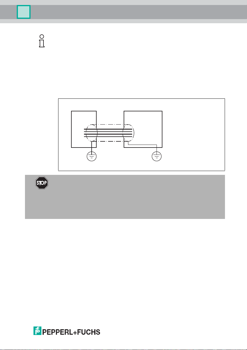
4.3.3 Handhelds
There are various handheld read/write devices available for controlling processes
(write/read functions, initialization of data carriers).
Figure 4.1
Handheld Frequency range
IPT-HH20 125 kHz
IST-HH20 250 kHz
IQT1-HH20 13.56 MHz
IC-HH20-V1 depending on the read/write head
2013-04
11
Page 12
IC-KP-B7-V95
1
PWR/
ERR
234
ESC
IC-KP-B7-V95
Part No. 130985
Module
Status
Network
Status
Com
Network
Pwr
Product Description
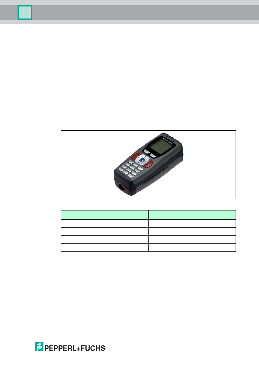
4.4 Displays and controls
The following displays and controls are located on the control interface.
LED indicators
PWR/ERR Power on
1, 2, 3, 4 Status display for R/W heads
Module status Device is operating in normal state
Network status Online, not connected
Network Pwr Network power supply available green
Com Data transfer (approx. 250 ms) Yel l ow
Hardware error
Command on R/W head is active
Command executed successfully (approx. 1 second)
Repairable errors (see chapter 9.1)
Irreparable errors – device must be replaced
Configuration requires modification (see chapter 9.1)
LED function test
Online, connected
Connection timeout
Critical connection error (duplicate MAC ID, bus
error)
green
red
green
yellow
green
red flashing
red
green flashing
red/green
flashing
green flashing
green
red flashing
red
12
Display
Two-line multifunction display with 12 characters per line for displaying different status and
operating information and four pictograms for displaying connected reading heads.
Push buttons
Push buttons are used for controlling the display and selecting commands when
programming the control interface.
ESC
Return to higher level
Up menu item
2013-04
Page 13
IC-KP-B7-V95
1
A
2
3
B
Product Description
Push buttons
Down menu item
RETURN (confirm input)
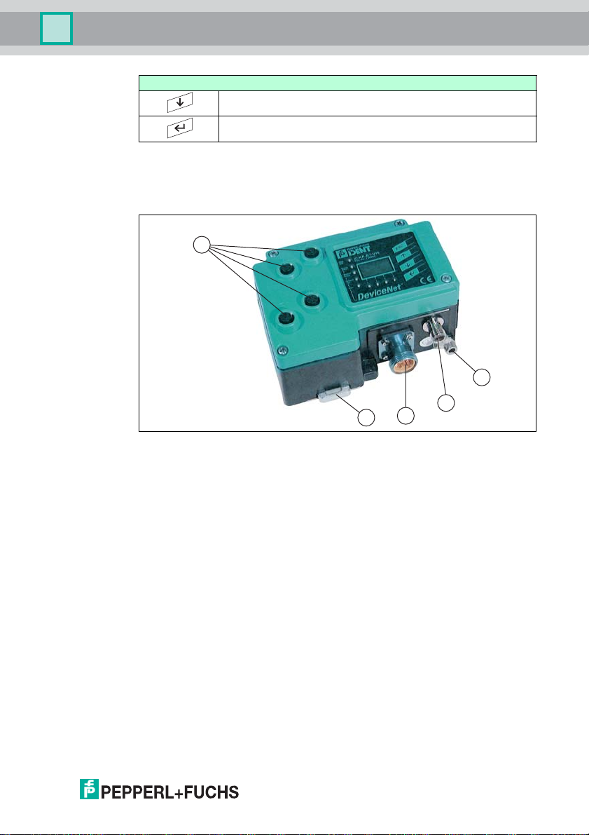
4.5 Interfaces and connections
The following interfaces and connections are located on the control interface ICKP-B7-V95.
Connections
1 M12 connector for R/W heads (sockets) - V1
2 M12 connector for power supply (plug) - V1
3 5-pin DeviceNet Ministyle connector
Other accessories
A Screw for gro und
B Metal latches for mounting the DIN rail
Accesso ries
Accessories see chapter 4.7.
4.6 Delivery package
The delivery package contains:
■ 1 IDENTControl control interface
■ 1 quick start guide
■ 1 grounding screw (already fitted)
■ 1 serrated lock washer (already fitted)
2013-04
■ 2 crimp connectors (already fitted)
13
Page 14
IC-KP-B7-V95
Product Description
4.7 Connection accessories
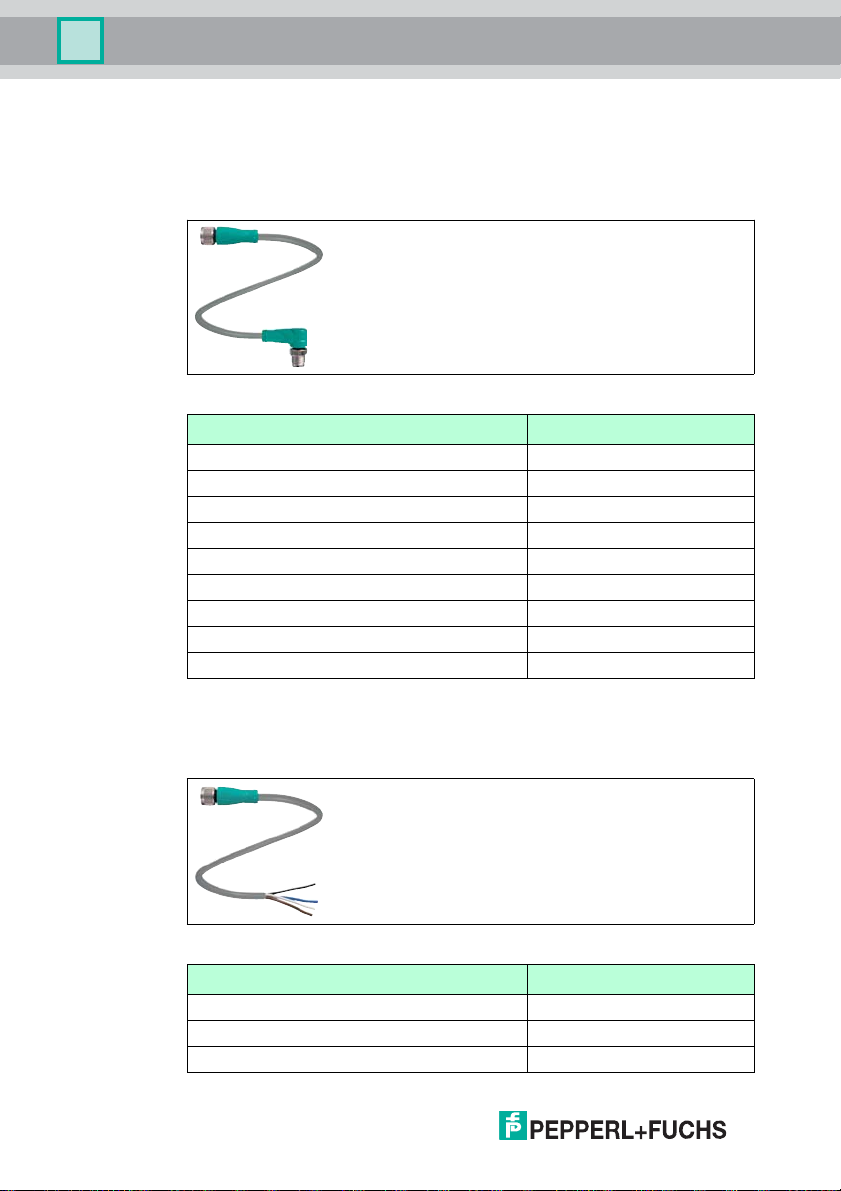
4.7.1 Connection cable for R/W heads and trigger sensors
Compatible connection cables with shielding are available for connecting the R/W
heads and trigger sensors.
Figure 4.2
Accessories Description
2 m long (straight female, angled male) V1-G-2M-P UR-ABG-V1-W
5 m long (straight female, angled male) V1-G-5M-P UR-ABG-V1-W
10 m long (straight female, angled male) V1-G -10M-PUR-ABG-V1-W
20 m long (straight female, angled male) V1-G -20M-PUR-ABG-V1-W
Field attachable female connector, straight, shielded V1-G-A BG-PG9
Field attachable male connector, straight, shielded V1S-G-ABG-PG9
Field attachable female connector, angled, shielded V1-W-ABG-PG9
Field attachable male connector, angled, shielded V1S-W-ABG-PG9
Dummy plug M12x1 VAZ -V1 -B3
4.7.2 Cable connectors for the power supply
Compatible M12 sockets with an open cable end for connecting the
IDENTControl to a power supply are available in different lengths.
Figure 4.3
Accessories Designation
Length 2 m (straight socket) V1-G-2M-P UR
Length 5 m (straight socket) V1-G-5M-P UR
Length 10 m (straight socket) V1-G -10M-PUR
14
2013-04
Page 15
IC-KP-B7-V95
Installation
5 Installation
5.1 Storage and transport
For storage and transport purposes, package the unit using shockproof
packaging material and protect it against moisture. The best method of protection
is to package the unit using the original packaging. Furthermore, ensure that the
ambient conditions are within allowable range.
5.2 Unpacking
Check the product for damage while unpacking. In the event of damage to the
product, inform the post office or parcel service and notify the supplier.
Check the package contents with your purchase order and the shipping
documents for:
■ Delivery quantity
■ Device type and version in accordance with the type plate
■ Accessories
■ Quick start guide
Retain the original packaging in case you have to store or ship the device again at
a later date.
Should you have any questions, please contact Pepperl+Fuchs.
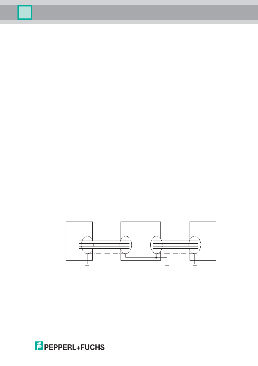
5.3 EMC concept
The outstanding noise immunity of the IDENTControl against emission and
immission is based on its consistent shielding design, which uses the principle of
the Faraday cage. Interference is caught in the shield and safely diverted via the
ground connections.
Read head ControlIDENTControl
DeviceNet
The cable shielding is used to discharge electromagnetic interference. When
shielding a cable, you must connect both sides of the shield to ground with low
resistance and low inductance.
2013-04
15
Page 16
IC-KP-B7-V95
4
13
2
Installation
Note!
If cables with double shields are used, e.g. wire mesh and metalized foil, the both
shields must be connected together, with low resistance, at the ends when
making up the cable.
Power supply cables are the source of much interference, e.g. from the supply
lines of 3-phase electric motors. For this reason, the parallel laying of power
supply cables with data and signal cables should be avoided, particularly in the
same cable duct.
The metal enclosure of the IDENTControl and the metal enclosure of the R/W
heads complete the consistent shielding concept.
The most important issue here is that the shields are connected to ground with
low resistance and low inductance. The metal enclosure ensures that the
shielding is not interrupted, i.e. the complete electronics system and all routed
cables are located within a Faraday cage.
Caution!
Due to the requirements in the DeviceNet specification, the shield on the bus
cable is connected to the device housing via an RC link.
5.4 Device connection
Electrical connection using plug connectors makes installation simple.
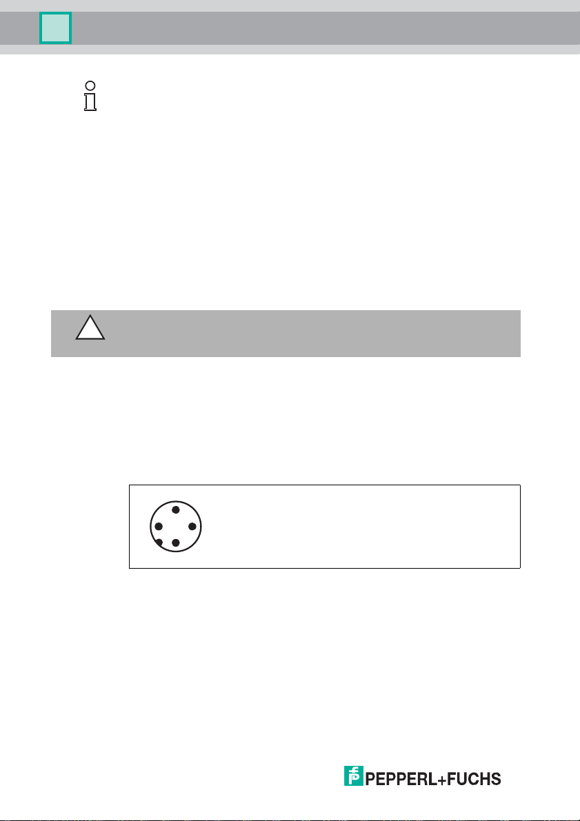
5.4.1 Power supply
Connect the power supply via an M12 connector with integrated voltage and
reverse polarity protection indicator (green: correct polarity, red: revers e polarity).
A plug with the following pin assignment is located on the housing:
1 + 24 V
2 NC
3 GND
4 NC
Compatible connecting cable see chapter 4.7.2.
16
2013-04
Page 17

IC-KP-B7-V95
trigger switch
trigger sensor
read/write head
signal
socket at housing
2
13
4
5
+
A
-
+
-
B
1
2
3
4
5
Installation
5.4.2 Read/Write Head and Trigger Sensors
A maximum of 4 read/write heads can be connected to the IDENTControl.
Instead of the read/write heads, a maximum of 2 trigger sensors can be
connected to sockets 3 and 4. A trigger sensor can be assigned to only one
read/write head. The trigger sensors must be PNP.
Connect the read/write heads and trigger sensors to the sockets on the top of the
enclosure using M12 connectors.
For details of compatible read/write heads, and of compatible connecting cables,
see chapter 4.7.1.
5.4.3 Cable length between control interface and R/W heads
The maximum cable length between the control interface and a connected R/W
head is 1000 meters. If you wish to attain the maximum possible cable length,
select a suitably large cable cross-section. See chapter 4.7.1
5.4.4 Ground connection
The ground connection of the IDENTControl is located at the lower right of the
connector array. The ground conductor is screwed to the housing with a crimp
connector. In order to guarantee safe grounding, the serrated washer must be
mounted between the crimp connector and the housing.
2013-04
12 43
1 Housing
2 Serrated lock washer
3 Crimp connector
4 Lock screw
A cross-section of at least 4 mm
2
is recommended for the ground conductor lead.
17
Page 18
IC-KP-B7-V95
2
4
1
3
5
Installation
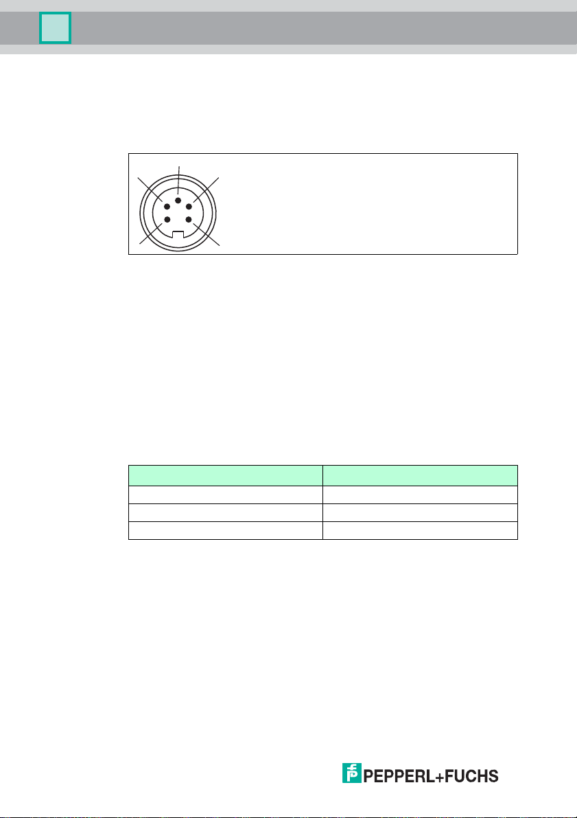
5.4.5 DeviceNet connection guide
Network connection
The network connection is established using a DeviceNet MiniStyle connector.
The pin assignment is taken from the drawing below.
1 Ground / uncoated
2 V+ / RD
3 V- / BK
4 CAN_H / WH
5 CAN_L / BU
Connecting cable
The device must always be connected using the "Thick" and "Thin" extension
cables described in the DeviceNet specification. Refer to the "Thick cable profile"
and "Thin cable profile" sections in the DeviceNet specification for more detailed
information.
Transfer rates and cable lengths
Baud rate Max. length of the transfer cable
125 kBits/s 500 m
250 kBits/s 250 m
500 kBits/s 100 m
2013-04
18
Page 19

IC-KP-B7-V95
Commissioning
6Commissioning
6.1 Connection
War ning !
Before commissioning, check once again that the connections are correct.
Before commissioning, familiarize yourself with the system of communication
between your DeviceNet control and the read/write station (see chapter 7).
Commissioning requires accurate knowledge of DeviceNet communication.
After the supply voltage is connected, the green LED in the voltage connector and
the PWR LED on the display panel must light up. If the LED in the connector lights
up red, the polarity of the power supply is reversed.
6.2 Preliminary considerations
A very important aspect of the operation of an extended identification system on
the DeviceNet is the time response of the overall system. The question "How long
after the positioning of a data carrier in front of a read/write station will the read
data be available in the computer or PLC?" cannot be answered universally.
The most important factors that determine the response time are:
■ Nature of the higher-level host system, e.g. PLC or PC
■ Communication between the client and server
■ Network utilization
■ Number and nature of connected read/write stations
■ Type of code/data carrier used
■ Nature of access to the communication objects of the read/write station
■ Nature of the commands to the read/write station
■ Structure of the user program
6.3 Device settings
War ning !
Device not configured or configured incorrectly
Configure the device prior to commissioning. A device that has not been
configured or configured incorrectly may lead to faults in the plant.
You must set the various parameters prior to commissioning.
The parameters are volatile and non-volatile parameters. Volatile parameters are
reset to their default setting when the system is switched off and on again.
2013-04
19
Page 20
IC-KP-B7-V95
Commissioning
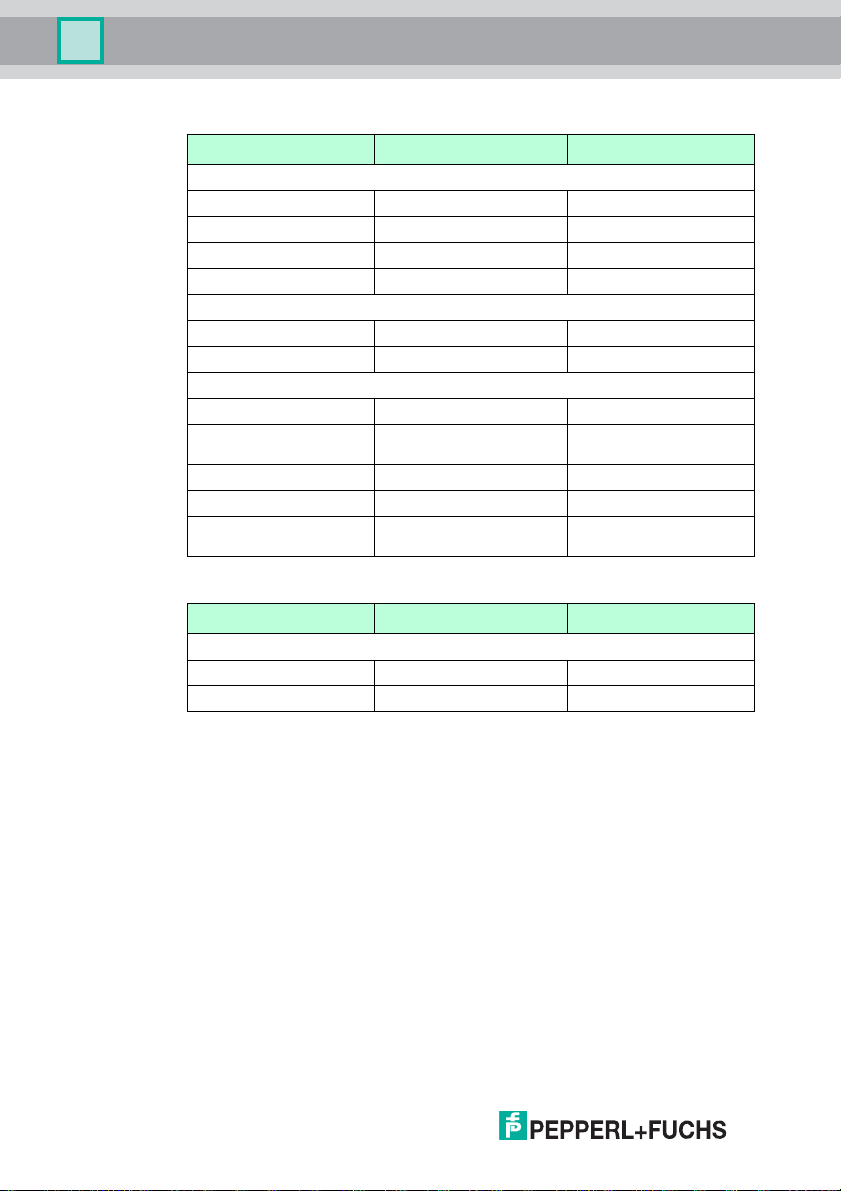
Non-volatile parameters
Par ame ter Default setting Value range
Ge n er a l
LCD c on trast 50 36 ... 71
LCD l ig ht On On / off
Language Eng lish English / German
Multiplex mode off On / off
R/W head
Trigger mode off On / off
Ta g t yp e 99 00 ... FF
DeviceNet interface
Network address 63d 00d ... 63d
Baud rate 125 kBit/s 125 kBit/s, 250 kBit/s,
Instance Out 100d 100d ... 112d
Instance In 150d 150d ... 162d
Data hold time 10 x 10 ms 000 x 10 ms ... 255d x 10
Volatile parameters
500 kBit/s
ms
20
Par ame ter Default setting Value range
R/W head
Password mode Off on / off
Password 00000000 00000000 ... FFFFFFFF
Configure the read/write station with the described system commands. "99" is
preset as the tag type.
2013-04
Page 21

IC-KP-B7-V95
Version
information
IPH1 IPH2 IPH3 IPH4
IDENTControl...
IPH1 IPH2 IPH3 IPH4
Config
IdentControl
IPH1 IPH2 IPH3 IPH4
Show Config
IdentControl
IPH1 IPH2 IPH3 IPH4
MultiplexM.
X
IPH1 IPH2 IPH3 IPH4
TagType
XX XX XX XX
IPH1 IPH2 IPH3 IPH4
TriggerMode
XXX
IPH1 IPH2 IPH3 IPH4
Triggerstate
H3:X H4:X
IPH1 IPH2 IPH3 IPH4
IdentGateway
IC-KP-B7-..
IPH1 IPH2 IPH3 IPH4
Reset
Config
IPH1 IPH2 IPH3 IPH4
Config
Channels
IPH1 IPH2 IPH3 IPH4
Aktivate
Command
IPH1 IPH2 IPH3 IPH4
Set Tag
(ChannelNo)
IPH1 IPH2 IPH3 IPH4
Version
ChannelNo:
IPH1 IPH2 IPH3 IPH4
EnhancedRead
Fixcode
IPH1 IPH2 IPH3 IPH4
ChannelNo: X
IPH1 IPH2 IPH3 IPH4
Enhanced
Read 1 Word
IPH1 IPH2 IPH3 IPH4
ChannelNo: X
IPH1 IPH2 IPH3 IPH4
Triggermode
...
IPH1 IPH2 IPH3 IPH4
Sensor Ch.
-> X
IPH1 IPH2 IPH3 IPH4
Quit
Command
IPH1 IPH2 IPH3 IPH4
ChannelNo: X
IPH1 IPH2 IPH3 IPH4
Reset
Identcontrol
IPH1 IPH2 IPH3 IPH4
Word-Address
XXXX
IPH1 IPH2 IPH3 IPH4
ChannelNo: X
IPH1 IPH2 IPH3 IPH4
ChannelNo: X
IPH1 IPH2 IPH3 IPH4
Tag Type
XX
IPH1 IPH2 IPH3 IPH4
IXH-XXXX
XX.XX.XX
IPH1 IPH2 IPH3 IPH4
Display
config
IPH1 IPH2 IPH3 IPH4
Select
language
IPH1 IPH2 IPH3 IPH4
LCD-Light
on/off
IPH1 IPH2 IPH3 IPH4
Adjust
LCD-Contrast
IPH1 IPH2 IPH3 IPH4
Reset
Config
IPH1 IPH2 IPH3 IPH4
Language
english
IPH1 IPH2 IPH3 IPH4
LCD-Contrast
XX
IPH1 IPH2 IPH3 IPH4
IDENT
Gateway...
IPH1 IPH2 IPH3 IPH4
Multiplexed
XXX
IPH1 IPH2 IPH3 IPH4
Multiplexed
Mode...
IPH1 IPH2 IPH3 IPH4
Set
Defaults?
IPH1 IPH2 IPH3 IPH4
Ident Ch.
-> X
IPH1 IPH2 IPH3 IPH4
Triggermode
XXX
IPH1 IPH2 IPH3 IPH4
Restart?
X
IPH1 IPH2 IPH3 IPH4
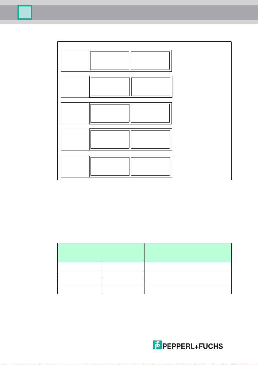
stands for pressing
ESC
stands for pressing
stands for pressing
stands for pressing
Direction
Direction
Direction
Direction
IPH1 IPH2 IPH3 IPH4
IPH1 IPH2 IPH3 IPH4
IPH1 IPH2 IPH3 IPH4
IPH1 IPH2 IPH3 IPH4
IPH1 IPH2 IPH3 IPH4
IPH1 IPH2 IPH3 IPH4
IPH1 IPH2 IPH3 IPH4
IPH1 IPH2 IPH3 IPH4
Address... MAC ID:
00-63
Baudrate...
125kBit/s
250kBit/s
Assembly
Instance
Out
100-In 150
Out
101-In 151
Datahold
Time
Datahold
T
x
10ms
500kBit/s
Out
112-In 162
...
Baudrate:
dhcp gültig
ja / nein
IPH1 IPH2 IPH3 IPH4IPH1 IPH2 IPH3 IPH4
Restart?
X
dhcp gültig
ja / nein
IPH1 IPH2 IPH3 IPH4IPH1 IPH2 IPH3 IPH4
Restart?
X
dhcp gültig
ja / nein
IPH1 IPH2 IPH3 IPH4IPH1 IPH2 IPH3 IPH4
Restart?
X
dhcp gültig
ja / nein
IPH1 IPH2 IPH3 IPH4IPH1 IPH2 IPH3 IPH4
Restart?
X
Commissioning
6.3.1 Operating the device
The following illustration shows how the device is operated directly:
2013-04
21
Page 22
IC-KP-B7-V95
Commissioning
6.4 Output of the contents of read data carriers on the display
In the first menu level, the IDENTControl shows the contents of read data carriers
on the display. Information messages of this kind are marked with a bell icon ( )
in the top right corner of the display to distinguish them from menu items.
A maximum of the first 12 characters of the read data set can be displayed. The
following characters may be excluded.
The view on the display can be toggled by pressing the arrow buttons. The
following display variants are available:
■ HEX (hexadecimal with decimal delimiter)
■ HEX2 (hexadecimal without decimal delimiter)
■ ASCII (ASC)
Note!
Data carrier content from commands that are activated manually on the
IDENTControl are always displayed, irrespective of the menu level that was just
displayed.
6.5 Setting the network parameters
The following parameters must be set manually via the display:
■ Bus address
■ Baud rate
■ Assembly instance
■ Data hold time
Caution!
Always use parameters that you know are compatible with your network.
Setting parameters
To set the parameters using the function buttons, proceed as follows:
1. Press return (confirm input).
2. Select IDENT gateway (down arrow button, return).
3. Press return to confirm the option Address ...
4. Enter the bus address using the arrow buttons.
5. Press return to save and exit the menu item.
6. Proceed with the options Baud rate, Assembly instance and Data hold time in
the same way.
7. Initiate a reset (menu) or disconnect the power supply to restart the device.
The settings only take effect after the reset.
2013-04
22
Page 23

IC-KP-B7-V95
Channel 1
Channel 2
Channel 3
Channel 4
Channel
IDENTControl
Class 64h
Instance 06 d
Attributes 1-4
1
Class 65h
Instance 06 d
Attributes 1-4
1
Input command objectOutput command object
Commands
7Commands
7.1 Communication via DeviceNet
7.1.1 General information on communication via DeviceNet
DeviceNet is an open fieldbus standard that enables data exchange between
programmable logic controllers (PLCs), personal computers (PCs), control and
monitoring systems as well as sensors and actuators. Please visit the ODVA
website at www.odva.org for more information about DeviceNet.
7.1.2 Performance spectrum
The DeviceNet has the following characteristics:
■ Group 2 only server
■ Data transfer via Poll I/O, change of state, cyclic I/O, explicit message
■ Supported transfer rates: 125 kBit/s, 250 kBit/s, 500 kBit/s
7.1.3 Electronic data sheet (EDS)
The device is supplied with an EDS file.
7.1.4 Data/Command transfer
The commands are transferred via DeviceNet/IP objects, i.e. objects from classes
04h, 64h, and 65h. There are always two different modes available, which may not
be confused: "Mixed mode" and "Separated mode".
7.1.5 Mixed mode
The five IDENT channels (four R/W heads, one configuration channel) are
addressed using an input and an output instance, with the advantage that the
controller requires less memory.
The different parameters of the IDENT telegram distinguish the channels.
2013-04
23
Page 24
IC-KP-B7-V95
Channel 1
Channel 2
Channel 3
Channel 4
Channel
Output command object Input command object
IDENTControl
Class 64h
Instance 03d
Attributes 1-4
1
Class 65h
Instance 03d
Attributes 1-4
1
Class 64h
Instance 05d
Attributes 1-4
1
Class 65h
Instance 05d
Attributes 1-4
1
Class 65h
Instance 01d
Attributes 1-4
1
Class 64h
Instance 02 d
Attributes 1-4
1
Class 65h
Instance 02 d
Attributes 1-4
1
Class 64h
Instance 04d
Attributes 1-4
1
Class 65h
Instance 04d
Attributes 1-4
1
Class 64h
Instance 01d
Attributes 1-4
1
Commands
7.1.6 Separated mode
Each IDENT channel is addressed using a separate input and separate output
instance. The advantage here is that data processing is simplified because
different IDENT channels do not have to process the data in the same memory
area.
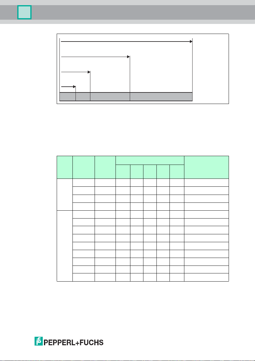
7.1.7 Data length
Depending on the data length required, four different attributes with different
lengths are available for each input/output instance.
Class 64h and 65h, instance 1-6
Attribute ID Data length Maximum number of double words (4
Attributes 1-3 require fewer data bytes than attribute 4.
1 8 1
2 12 2
3 32 7
4 60 14
bytes) that can be read/written at any one
time
24
2013-04
Page 25
IC-KP-B7-V95
attribute 4
attribute 3
attribute 2
attribute
1
Commands
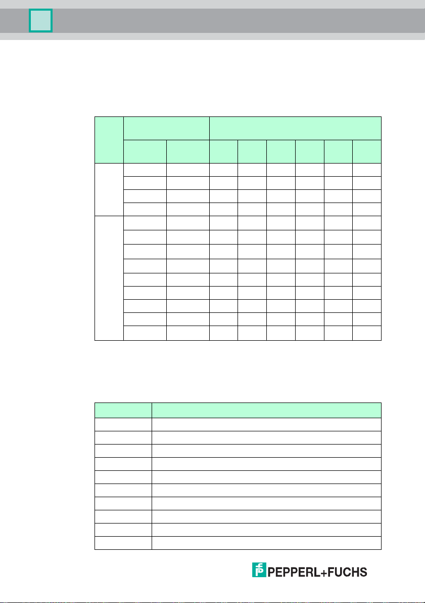
7.1.8 Assembly attributes
The attributes of the output object (class 64h) and the input objects (class 65h)
appear in different combinations in the assembly object. 26 assembly instances
can be used in pairs for implicit communication and so there are 13 possible
combinations. These combinations can be selected either via the device display,
the attribute 100 from instance 0 of the assembly object or by specifying the
combination on the PLC (Forward Open).
Mixed
mode
Sepa-
rated
mode
Output
instance
100d 150d 8* 8 / 8
101d 151d 12* 12 / 12
102d 152d 32* 32 / 32
103d 153d 60* 60 / 60
104d 154d 8 8 8 8 32 / 32
105d 155d 12 12 12 12 48 / 48
106d 156d 32 32 32 32 128 / 128
107d 157d 60 60 60 60 240 / 240
108d 158d 8 8 8 8 8 40 / 40
109d 159d 12 12 12 12 8 56 / 56
110d 160d 32 32 32 32 8 136 / 136
111d 161d 60 60 60 60 8 248 / 248
112d 162d 0 / 10 0 / 10
Input
instance
Channel size Required/Generated
1 2 3 4 5
(conf.)
size
Output/Input byte
* access to mixed mode instance for input/output command object
The following comparison shows the relationship between input and output
instances: Input instance = output instance + 50d.
A combination of the "heartbeat" and the ident status forms the output instance
112 and input instance 162. Refer to appendix B for a more detailed view of the
2013-04
object model.
25
Page 26
IC-KP-B7-V95
Commands
7.1.9 Access administration
The assembly object is a collection of attributes from classes 64h and 65h (input
and output). Both implicit and explicit access to these objects is possible (via the
assembly object). Simultaneous access is regulated as follows to prevent the
attributes from overwriting one another.
Implicit data
exchange
Mixed
mode
Sepa-
rated
mode
Output
instance
100d 150d x x x x x x
101d 151d x x x x x x
102d 152d x x x x x x
103d 153d x x x x x x
104d 154d x x x x x
105d 155d x x x x x
106d 156d x x x x x
107d 157d x x x x x
108d 158d x x x x x x
109d 159d x x x x x x
110d 160d x x x x x x
111d 161d x x x x x x
112d 162d x
Input
instance
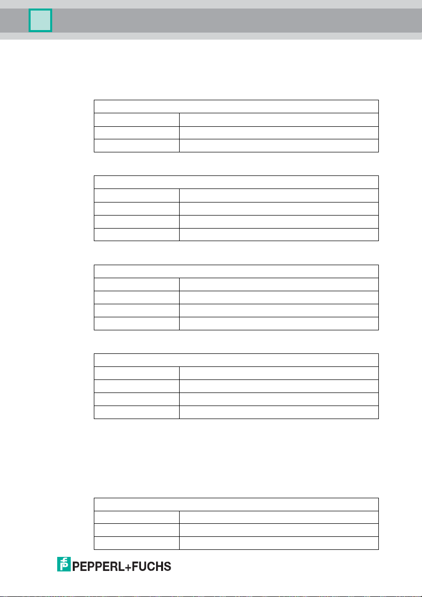
7.1.10 Heartbeat and ident status
If instance 112d and 162d of the assembly object are selected, the size of the
output field is 0 bytes and the size of the input that contains the status and reply
counter is 10 bytes.
Byte status Description
00 Status of the IDENTControl
01 Reply counter of the IDENTControl
02 Status of channel 1
03 Reply counter from channel 1
04 Status of channel 2
05 Reply counter from channel 2
06 Status of channel 3
07 Reply counter from channel 3
08 Status of channel 4
09 Reply counter from channel 4
26
Explicit access
Instances from input/o utput commands
1 2 3 4 5
(conf.)
6
2013-04
Page 27

IC-KP-B7-V95
Commands
The advantage of this procedure is that only a few data bytes are transferred via
the bus. Ident commands are transferred as the ident system as explicit
commands. A new ident response can be read as soon as the value on the reply
counter changes.
7.1.11 Data hold time
All responses from the device are present in the input field for a specific time.
Make sure that the controller reads all responses before they are overwritten by a
new response. The data hold time indicates how long an IDENT telegram of this
kind remains in the input field. The data hold time can be adjusted via the display
or the boot-up object (see chapter 12.1). Values between 0 and 2.55 seconds can
be preset in 10 ms increments. The default value is 100 ms. Make sure that the
data hold time is greater than the maximum cycle time of the whole system
(including data storage to the PLC). However, the data hold time should not be
much longer than necessary for the following reasons:
1. The reaction time of the device will increase if several responses arrive in
quick succession.
2. The maximum possible number of response telegrams per time unit de-
creases when the data hold time is increased. A memory overflow may occur. The State LED then flashes green.
7.2 Command Execution
The controller initiates an identification command. If the data has changed since
the last read-out, the c ontrol interface executes the new command If the control
interface is scheduled to execute a command a number of times, the toggle bit
must be inverted. Only then does the device detect that the command has to be
executed again.
If the control interface detects a new command, it sets the status in the input field
to FFh. The reply counter value increases by 1. The status is displayed () after the
control interface has executed the commands.
The toggle bit of the response is the same as the toggle bit of the command.
When new data becomes available, the previous data is overwritten. The reply
counter value increases by 1. In the event of an overflow, the reply counter is reset
to its start value (01h).
New commands may only be sent to an output field after the response from the
previous command is read.
For an overview of supported commands, .
2013-04
27
Page 28

IC-KP-B7-V95
Commands
Command:
Byte 0* Telegram length, high byte
Byte 1* Telegram length, low byte
Byte 2 Command code
Byte 3 Channel/toggle bit = 0
Byte 4 Parameters
Byte 5 Parameters
Byte 6 Data to be written
... ...
Byte N Data to be written
Table 7.1 * This byte is only used with the TCP/IP and MODBUS TCP/IP protocol.
Confirmation (with MODBUS/TCP, no confirmation is sent)
Byte 0* Telegram length, high byte
Byte 1* Telegram length, low byte
Byte 2 Command code (echo)
Byte 3 Channel/toggle bit (echo) = 0
Byte 4 Status FFh
Byte 5 Reply cou nter
... 00h
Byte N 00h
Table 7.2 * This byte is only used with the TCP/IP and MODBUS TCP/IP protocol.
28
Response:
Byte 0* Telegram length, high byte
Byte 1* Telegram length, low byte
Byte 2 Command code (echo)
Byte 3 Channel/toggle bit (echo) = 0
Byte 4 St atu s
Byte 5 Reply cou nter
Byte 6 Read data
... ...
Byte N Read data
Table 7.3 * This byte is only used with the TCP/IP and MODBUS TCP/IP protocol.
2013-04
Page 29
IC-KP-B7-V95
Commands
7.2.1 Command examples
Example: Define tag type
Command: Change tag type on channel 1 to IPC03
04:02:30:33 (hexadecimal format)
04 Command code CT (change tag)
02 Reserved/Channel (1), toggle bit 0b
30:33 tag type (IPC03)
Confirmation
04:02:FF:01
04 Repeat command code CT (change tag)
02 Reserved/Channel (1), toggle bit 0b
FF Status FFh (processing command)
01 Rep ly counter
Response: Type IPH-... read/write head on channel 1
04:02:00:02
04 Repeat command code CT (change tag)
02 Reserved/Channel (1), toggle bit 0b
00 Status 0 (command executed without error)
02 Rep ly counter
Alternative response: No read/write head on channel 1
04:02:06:02
04 Repeat command code CT (change tag)
02 Reserved/Channel (1), toggle bit 0b
06 Status 6 (hardware error)
02 Rep ly counter
Example: Read tag
Prerequisites:
■ The tag type IPC03 is set.
■ One type IPH-… read/write head is connected to channel 1.
Command: Read two double words starting from address 0 on channel 1
10:22:00:00
10 Command code SR (single read words)
22 Number of double words (2) / channel (1), toggle bit
2013-04
00:00 Address of double words (0000)
29
Page 30

IC-KP-B7-V95
Commands
Confirmation
10:22:FF:01
10 Repeat command code SR (single read words)
22 Number of double words (2) / channel (1), toggle bit
FF Status FFh (processing command)
01 Rep ly counter
Response: Type IPC03 tag is located in front of the read/write head, the
highlighted part depends on the content of the tag
10:22:00:02:31:32:33:34:35:36:37:38
10 Repeat command code SR (single read words)
22 Number of double words (2) / channel (1), toggle bit
00 Status 0 (command executed without error)
02 Rep ly counter
31:32:33:34:35:36:37:38 Data
Alternative response: No tag in front of read/write head
10:02:05:02
10 Repeat command code SR (single read words)
02 Number of double words (0) / channel (1), toggle bit
05 Status 5 (no tag in the detection range)
02 Rep ly counter
7.3 Command types
When using commands, a distinction is always made between the two command
types single mode and enhanced mode.
Single mode
The command is executed once. A response is issued immediately.
Enhanced mode
The command remains permanently active until it is interrupted by the user or by
an error message. A response is issued immediately.
The command remains active after the response is issued. Data is only
transferred if read/write tags change. Read/write tags are not read twice. If a
read/write tag leaves the read range, the status '5' is output.
30
2013-04
Page 31

IC-KP-B7-V95
Commands
7.4 Command overview
The commands in the list are described in detail on the following pages.
System commands
Command
code
4d 04h See "Change tag (CT):" on page 33 CT
2d 02h See "Quit (QU):" on page 36 QU
22d 16h See "Reset (RS):" on page 36 RS
155d 9Bh See "Set multiplexed mode (MM):" on page 37 MM
156d 9Ch See "Set trigger mode (TM):" on page 38 TM
Standard read/write commands
Fixcode
Command
code
1d 01h See "Single read read only code (SF):" on page 39 SF
29d 1Dh
Read data
Command description
Command description
See "Enhanced buffered read read only code (EF):" on page 40
Abbre
viation
Abbre
viation
EF
Command
code
16d 10h See "Single read words (SR):" on page 41 SR
25d 19h See "Enhanced buffered read words (ER):" on page 42 ER
Command description
Abbre
viation
Write data
Command
code
64d 40h See "Single write words (SW):" on page 43 SW
26d 1Ah See "Enhanced buffered write words (EW):" on page 44 EW
Command description
Abbre
viation
Special command modes
Password mode with IPC03
Command
code
24d 18h See "Set password mode (PM):" on pag e 47 PM
65d 41h See "Change password (PC):" on page 48 PC
66d 42h See "Set password (PS):" on page 49 PS
2013-04
Command description
Abbre
viation
31
Page 32

IC-KP-B7-V95
Commands
IPC03 configuration
Command
code
97d 61h See "Single get configuration (SG):" on page 50 SG
104d 68h See "Enhanced buffered get configuration (EG):" on page 51 EG
18d 12h See "Single write configuration (SC):" on page 52 SC
102d 66h
Extended commands for tag type IPC11 and IDC-...-1K
Command
code
31d 1Fh See "Single write read only code (SX):" on page 54 SX
36d 24h
188d BCh See "Set tag ID code (TI)" on page 56 TI
170d AAh See " Fill data carrier (S#)" on page 57 S#
Extended commands for tag type IDC-...-1K
Command
code
10d 0Ah See "Single read special f ixcode (SS)" on page 58 SS
113d 71h See "Enhanced read special fixcode (ES)" on page 59 ES
13d 0Dh See "Single program special fixcode (SP)" on page 60 SP
117d 75h See "Enhanced program special fixcode (EP)" on page 61 EP
107d 6Bh See "Initialize data carrier (SI):" on page 62 SI
Command description
See "Enhanced buffered write configuration (EC):" on page 53
Command description
See "Enhanced buffered write read only code (EX):" on page 55
Command description
Abbre
viation
EC
Abbre
viation
EX
Abbre
viation
32
Extended commands for IQH2-... read/write heads
Command
code
190d BEh See "read param (RP)" on page 63 RP
191d BFh See "write param (WP)" on page 64 WP
Command description
Abbre
viation
2013-04
Page 33

IC-KP-B7-V95
Commands
7.4.1 System commands
Change tag (CT):
Byte Contents Bit no.
7 6 5 4 3 2 1 0
Byte 0 Command code (04h) 0 0 0 0 0 1 0 0
Byte 1
Byte 2 Tag ty p e i n A S CI I <TagType> (high byte)
Byte 3 Tag ty p e i n A S CI I <TagType> (low byte)
Response:
Byte Contents Bit no.
Byte 0 Command code (04h) 0 0 0 0 0 1 0 0
Byte 1
Byte 2 Status <Status>
Byte 3 Reply counter <ReplyCounter>
This command tells the read/write head on the relevant channel which tag type to
communicate with. This setting is stored in the non-volatile memory on the unit.
S u p po rte d Ta g Ty p e s
Ta g ty pe P+F
High
byte
'0' '2' IPC02 Unique, EM4102 (EM
'0' '3' IPC03 EM4450 (EM
'1' '1' IPC11 Q5 (Sokymat) Read/write 5 - 125 kHz
'1' '2' IPC12 P+F FRAM Read/wr ite
'2' '0'
'2' '1' IQC21 I-Code SLI (NXP) Read/wr ite
'2' '2' IQC22 Tag-it HF-I Plus (Texas
2013-04
Low
byte
designation
IQC20
Reserved/Ident channel/Toggle bit
Reserved/Ident channel/Toggle bit
Chip type Access Writable
microelectronic)
microelectronic), Titan
1)
All ISO 15693 compliant
read/wri te tags
Instruments)
0 0 0 0 <Channel> <T>
7 6 5 4 3 2 1 0
0 0 0 0 <Channel> <T>
Read only
code
Read/write
read onl y
code
read onl y
code
Read/write
read onl y
code
read onl y
code
Read/write
read onl y
code
memory
[bytes]
116 4 125 kHz
8k 4 125 kHz
112 8 13.56 MHz
250 8 13.56 MHz
Read
only
code
length
[byte]
5 5 125 kHz
8 8 13.56 MHz
Fre quenc y
range
33
Page 34

IC-KP-B7-V95
Commands
Ta g ty pe P+F
High
byte
Low
byte
designation
'2' '3' IQC23 my-D SRF55V02P
'2' '4' IQC24 my-D SRF55V10P
'3' '1' IQC31 Tag -i t HF - I Sta nd ar d
'3' '3'
IQC33
'3' '4' IQC34 FRAM MB89R119
'3' '5' IQC35 I-Code SLI-S (NXP) Read /write
'4' '0' IQC40 All ISO 14443A compliant
'4' '1' IQC41 Mifare UltraLight MF0 IC
'4' '2'
'4' '3'
IQC42
IQC43
'5' '0' IDC-...-1K P+F Read/write
'5' '2' ICC-... P+F Read only
'7' '2'
'7' '3'
'7' '4'
'7' '5'
'7' '6'
IUC72
IUC73
IUC74
IUC75
IUC76
Chip type Access Writable
(Infinion)
(Infinion)
(Texas Instruments)
2)
FRAM MB89R118
(Fujitsu)
(Fujitsu)
read/wri te tags
U1 (NXP)
3)
Mifare Classic MF1 IC
S50 (NXP)
3)
Mifare Classic MF1 IC
S70 (NXP)
Read/write
read onl y
code
Read/write
read onl y
code
Read/write
read onl y
code
Read/write
read onl y
code
Read/write
read onl y
code
read onl y
code
Read only
code
Read/write
read onl y
code
Read/write
read onl y
code
Read/write
read onl y
code
read onl y
code
code
4)
UCode-EPC-G2XM
(NXP)
4)
4)
4)
4)
Higgs-2 (Alien) Read only
UCode-EPC-G2 (NXP) Read/write
Monza 2.0 (Impinj) Read only
Higgs-3 (Alien) Read/wr ite
Read/write
read onl y
code
code
read onl y
code
code
read onl y
code
memory
[bytes]
Read
only
code
length
[byte]
Fre quenc y
range
224 8 13.56 MHz
928 8 13.56 MHz
32 8 13.56 MHz
2k 8 13.56 MHz
29 8 13.56 MHz
160 8 13.56 MHz
-
4/7
6)
13.56 MHz
48 7 13.56 MHz
752
3440
4/7
4/7
6)
6)
13.56 MHz
13.56 MHz
125 4 250 kHz
28 7 250 kHz
64 8 868 MHz
- 96 868 MHz
28 96 868 MHz
- 96 868 MHz
56 240 868 MHz
34
2013-04
Page 35

IC-KP-B7-V95
Commands
Ta g ty pe P+F
High
byte
'8' '0' All Class 1 Gen 2 compliant read/write
'9' '9'
1)
IQC20 is not an actual tag type as such, but is used to read the UID (read only code) of all ISO 15693
compliant read/write tags.
2)
Read/write tag IQC33 can only be used in combination with a IQH1-... read/write head. The memory is
divided into 8-byte blocks (instead of 4-byte blocks). You must enter a continuous initial address for write
commands SR, ER, SW and EW.
<WordNum> specifies the number of 8-byte blocks (here, max. 7) and must be an even number.
3)
Read/write tags I QC40–IQC43 can only be used in combination with a IQH2-... read/write head.
<WordNum> specifies the number of 16-byte blocks and must be a multiple of 4.
The memory can be encrypted for each sector (1 sector = 4 blocks of 16 bytes).
The default key in the tag and reader is FF FF FF FF FF FF
using the Read param command and written using the Write para m command (see System
Commands). The key is only changed in the reader during this process and not in the tag!
The key in the reader is stored in the non-volatile memory.
4)
IUC7* type read/write tags can only be used with read/write head IUH-F117-V1 in combination with
certain control interfaces.
5)
The tag type configured in the read/write head as the default is selected.
6)
Read/write tags can have 4-byte (older versions) or 7-byte UIDs. IQC42 and IQC43 type read/write tags
from Pepperl+Fuchs generally have 7-byte UIDs.
Low
byte
designation
Chip type Access Writable
tags
Depends on the reader
5)
- - Max. 96 868 MHz
- - - -
memory
[bytes]
. The key in the reader can be read
ASCII
Read
only
code
length
[byte]
Fre quenc y
range
Note!
In a plant where only one tag type is used, it is advantageous to permanently
configure that tag type so that the read/write head detects the tag quicker.
Default tag type:
In the factory default condition, the tag type 99 is preset in the IDENTControl
(depending on the reading head type), thus the tag type preset on the reading
head is used.
Recommendation:
For operation in an automated plant, permanently preset the data carrier type in
use via a command.
2013-04
35
Page 36

IC-KP-B7-V95
Commands
Quit (QU):
Byte Contents Bit no.
Byte 0 Command code (02h) 0 0 0 0 0 0 1 0
Byte 1
Response:
Byte Contents Bit no.
Byte 0 Command code (02h) 0 0 0 0 0 0 1 0
Byte 1
Byte 2 Stat us <Status>
Byte 3 Reply counter <ReplyCounter>
The command running on this channel is interrupted.
Reset (RS):
Byte Contents Bit no.
Byte 0 Command code (16h) 0 0 0 1 0 1 1 0
Byte 1 Reserved/Channel/Toggle bit 0 0 0 0 0 0 0 <T>
Reserved/Ident channel/Toggle bit
Reserved/Ident channel/Toggle bit
7 6 5 4 3 2 1 0
0 0 0 0 <Channel> <T>
7 6 5 4 3 2 1 0
0 0 0 0 <Channel> <T>
7 6 5 4 3 2 1 0
36
This command terminates all active commands. The device settings are reloaded
from the non-volatile memory.
This confirmation is issued for this command (status FFh) instead of a response.
The device resets the hardware and then restarts.
2013-04
Page 37

IC-KP-B7-V95
Commands
Set multiplexed mode (MM):
Byte Contents Bit no.
Byte 0 Command code (9Bh) 1 0 0 1 1 0 1 1
Byte 1 Reserved/Toggle bit 0 0 0 0 0 0 0 <T>
Byte 2 Multiplex mode 0 0 0 0 0 0 0 <F>
Response:
Byte Contents Bit no.
Byte 0 Command code (9Bh) 1 0 0 1 1 0 1 1
Byte 1 Reserved/Toggle bit 0 0 0 0 0 0 0 <T>
Byte 2 Stat us <Status>
Byte 3 Reply counter <ReplyCounter>
This command switches multiplex mode on and off. In multiplex mode, the R/W
heads are controlled according to the time multiplex process, i.e. only one R/W
head is active. The procedure minimizes mutual interference between R/W
heads, allowing two R/W heads to be mounted side by side.
Each IDENT channel sends a response in reply to an MM command.
7 6 5 4 3 2 1 0
7 6 5 4 3 2 1 0
Multiplex mode <F>='0': Mode off
<F>='1': Mode on
If a R/W head is not connected to a channel, the response telegram receives the
status "06h" (hardware fault) from this channel.
2013-04
37
Page 38

IC-KP-B7-V95
Commands
Set trigger mode (TM):
Byte Contents Bit no.
Byte 0 Command code (9Ch) 1 0 0 1 1 1 0 0
Byte 1
Byte 2 Trigger mode <Trigger mode>
Response:
Byte Contents Bit no.
Byte 0 Command code (9Ch) 1 0 0 1 1 1 0 0
Byte 1
Byte 2 Stat us <Status>
Byte 3 Reply counter <ReplyCounter>
Permitted parameters:
<Sensor channel> 3 (011b), 4 (100b)
<Ident channel> 1 (0001b), 2 (0010b), 3 (0011b), 4 (0100b)
<Trigger mode> 0 (00000000b): Trigger mode off
Ident chan nel/sen sor channel /toggle bit
Reserved/sensor channel/toggle bit
(but not <Sensor channel>)
1 (00000001b): Trigger mode on
2 (00000010b): Trigger mode inverted
7 6 5 4 3 2 1 0
0 <Ident channel> <Sensor channel> <T>
7 6 5 4 3 2 1 0
0 0 0 0 <Sensor channel> <T>
38
2013-04
Page 39

IC-KP-B7-V95
Commands
7.4.2 Standard read/write commands
Single read read only code (SF):
Byte Contents Bit no.
Byte 0 Command code (01h) 0 0 0 0 0 0 0 1
Byte 1 Reserved/Channel/Toggle bit 0 0 0 0 <Channel> <T>
Response:
Byte Contents Bit no.
Byte 0 Command code (01h) 0 0 0 0 0 0 0 1
Byte 1 Reserved/Channel/Toggle bit 0 0 0 0 <Channel> <T>
Byte 2 Stat us <Status>
Byte 3 Re ply c ounter <ReplyCounter>
Byte 4 ID code 00h ... FFh <ID code>
Byte 5 ID code 00h ... FFh <ID code>
... ID code 00h ... FFh <ID code>
1)
Byte N
ID code 00h ... FFh <ID code>
1. N = <FixLen> + 3
7 6 5 4 3 2 1 0
7 6 5 4 3 2 1 0
The R/W head makes only one attempt to read a read only code.
The length of the read only code that is output depends on the tag type. See table
"Supported Tag Types" on page 33.
2013-04
39
Page 40

IC-KP-B7-V95
Commands
Enhanced buffered read read only code (EF):
Byte Contents Bit no.
Byte 0 Command code (1Dh) 0 0 0 1 1 1 0 1
Byte 1 Reserved/Ichannel/Toggle bit 0 0 0 0 <Channel> <T>
Response:
Byte Contents Bit no.
Byte 0 Command code (1Dh) 0 0 0 1 1 1 0 1
Byte 1
Byte 2 Stat us <Status>
Byte 3 Reply counter <ReplyCounter>
Byte 4 ID code 00h ... FFh <ID code>
Byte 5 ID code 00h ... FFh <ID code>
... ID code 00h ... FFh <ID code>
Byte N
7 6 5 4 3 2 1 0
7 6 5 4 3 2 1 0
Reserved/Ident channel/Toggle bit
1)
ID code 00h ... FFh <ID code>
0 0 0 0 <Channel> <T>
1. N = <FixLen> + 3
40
The R/W head makes attempts until successful to read a read only code. Only
data that changes is transferred via the interface, i.e. the R/W head transfers data
whenever it reads a new read/write tag or whenever it reads a read/write tag
where there was previously no read/write head within the detection range.
The status '05h' (read command) is output whenever a read/write tag leaves the
detection range.
The length of the read only code that is output depends on the tag type. See table
"Supported Tag Types" on page 33.
2013-04
Page 41

IC-KP-B7-V95
Commands
Single read words (SR):
Byte Contents Bit no.
Byte 0 Command code (10h) 0 0 0 1 0 0 0 0
Byte 1
Byte 2 Word address <WordAddr>(high byte)
Byte 3 Word address <WordAddr> (low byte)
Response:
Byte Contents Bit no.
Byte 0 Command code (10h) 0 0 0 1 0 0 0 0
Byte 1
Byte 2 Status <Status>
Byte 3 Reply counter <ReplyCounter>
Byte 4 Data 00h ... FFh < Data>
Byte 5 Data 00h ... FFh < Data>
Byte 6 Data 00h ... FFh < Data>
Byte 7 Data 00h ... FFh < Data>
... Data 00h ... FFh <Data>
Byte N
7 6 5 4 3 2 1 0
Word number/Channel/Toggle bit
Word number/Ident channel/Toggle bit
1)
Data 00h ... FFh <Data>
<WordNum> <Channel> <T>
7 6 5 4 3 2 1 0
<WordNum> <Channel> <T>
1. N = 4 x <WordNum> + 5; Ethernet/IP: N = 4 x <WordNum> + 3
The R/W head makes one attempt to read <WordNum> 32-bit words from the
address<WordAddr>.
2013-04
41
Page 42

IC-KP-B7-V95
Commands
Enhanced buffered read words (ER):
Byte Contents Bit no.
Byte 0 Command code (19h) 0 0 0 1 1 0 0 1
Byte 1
Byte 2 Word address <WordAddr>(high byte)
Byte 3 Word address <WordAddr> (low byte)
Response:
Byte Contents Bit no.
Byte 0 Command code (19h) 0 0 0 1 1 0 0 1
Byte 1
Byte 2 Status <Status>
Byte 3 Reply counter <ReplyCounter>
Byte 4 Data 00h ... FFh < Data>
Byte 5 Data 00h ... FFh < Data>
Byte 6 Data 00h ... FFh < Data>
Byte 7 Data 00h ... FFh < Data>
... Data 00h ... FFh <Data>
Byte N
7 6 5 4 3 2 1 0
Word number/Ident channel/Toggle bit
Word number/Ident channel/Toggle bit
1)
Data 00h ... FFh <Data>
<WordNum> <Channel> <T>
7 6 5 4 3 2 1 0
<WordNum> <Channel> <T>
1. N = 4 x <WordNum> + 5; Ethernet/IP: N = 4 x <WordNum> + 3
42
The R/W head makes attempts until successful, to read <WordNum> 32-bit words
from the address <WordAddr>. Only modified data is transferred via the interface.
When a read/write tag leaves the detection range, the status '05h' (read
command) is output.
2013-04
Page 43

IC-KP-B7-V95
Commands
Single write words (SW):
Byte Contents Bit no.
Byte 0 Command code (40h) 0 1 0 0 0 0 0 0
Byte 1
Byte 2 Word address <WordAddr>(high byte)
Byte 3 Word address <WordAddr> (low byte)
Byte 4 Data 00h ... FFh < Data>
... Data 00h ... FFh <Data>
Byte N
Response:
Byte Contents Bit no.
Byte 0 Command code (40h) 0 1 0 0 0 0 0 0
Byte 1
Byte 2 Status <Status>
Byte 3 Reply counter <ReplyCounter>
7 6 5 4 3 2 1 0
Word number/Ident channel/Toggle bit
1)
Data 00h ... FFh <Data>
<WordNum> <Channel> <T>
1. N = 4 x <WordNum> + 5; Ethernet/IP: N = 4 x <WordNum> + 3
7 6 5 4 3 2 1 0
Word number/Ident channel/Toggle bit
<WordNum> <Channel> <T>
The R/W head makes one attempt to write <WordNum> 32-bit words from the
address<WordAddr>.
2013-04
43
Page 44

IC-KP-B7-V95
Commands
Enhanced buffered write words (EW):
Byte Contents Bit no.
Byte 0 Command code (1Ah) 0 0 0 1 1 0 1 0
Byte 1
Byte 2 Word address <WordAddr>(high byte)
Byte 3 Word address <WordAddr> (low byte)
Byte 4 Data 00h ... FFh < Data>
... Data 00h ... FFh <Data>
Byte N
Response:
Byte Contents Bit no.
Byte 0 Command code (1Ah) 0 0 0 1 1 0 1 0
Byte 1
Byte 2 Status <Status>
Byte 3 Reply counter <ReplyCounter>
7 6 5 4 3 2 1 0
Word number/Ident channel/Toggle bit
1)
Data 00h ... FFh <Data>
<WordNum> <Channel> <T>
1. N = 4 x <WordNum> + 5; Ethernet/IP: N = 4 x <WordNum> + 3
7 6 5 4 3 2 1 0
Word number/Ident channel/Toggle bit
<WordNum> <Channel> <T>
The read/write head repeatedly attempts to write <WordNum> 32-bit words from
the address <WordAddr> until successful. After each successful write, the head
sends the response and then switches to continuous read. The read/write head
then reads the same tag until the tag has left the detection range or a new tag
appears within the detection range. At this point, the read/write head again starts
write attempts.
The status '05h' is only output when a tag leaves the detection range or is not yet
within the detection range.
If two tags enter the read range one immediately after the other, the status '05h' is
not issued between the two readings.
7.4.3 Special command modes
Note!
You can only use the commands in this section for the data carrier type '03'
(IPC03).
IPC03 Configuration
The storage of a data carrier IPC03 is organized by word. A data word is defined
with a length of 32 bits. For the normal data range, 29 words from addresses 3
through 31 (<WordAddr> = 00h ... 1Ch) are available.
44
2013-04
Page 45

IC-KP-B7-V95
Commands
Address Meaning <WordAddr> <ConfAddr> Note
Word 0 Password - - Write only
Word 1 Protection word - 1 Read/wr ite
Word 2 Control word - 2 Read/wr ite
Word 3 ...31 Data range 00h ... 1Ch - Read /write
Word 32 Device Serial Number 1Dh - Read only
Word 33 Device identification 1Eh - Read onl y
Word 0 contains the password. The password can only be w ritten.
With word 1, the "Protection Word", you can define a read-protected and a writeprotected range. The "Protection Word" can only be read and written with the
correct password.
With word 2, the "Control Word", you can set various operating modes and the
read range for the operating mode "Default Read". The "Control Word" can only
be read and written with the correct password.
If you would like to use the "Protection Word" and the "Control Word", you must
first activate the password mode.
The individual bits have the following meanings:
Protection word
Bit Meaning Byte
0 ... 7 First read-p rotected word 0
8 ... 15 Last read-protected word 1
16 ... 23 First write-protected word 2
24 ... 31 L ast write-protected word 3
Control word
Bit Meaning Byte
0 ... 7 Read range start 0
8 ... 15 Read range end 1
16 Password mode on/off 2
17 "Read after write" operating mode
18 ... 23 Open
24 ... 31 Open 3
on/off
IPC03 password mode
If the password mode in the data carrier is activated, the data range of the data
carrier is read and write-protected and can only be read or written if the R/W head
2013-04
sends the correct password to the data carrier.
45
Page 46

IC-KP-B7-V95
Commands
If the password mode in the data carrier is deactivated, every data word on the
data carrier can be read or written.
The default password of the R/W heads and the data carrier is 00000000h. In the
R/W head, the password is stored in the volatile memory and in the data carrier,
the password is stored in the non-volatile memory.
To read or write the "Protection Word" and the "Control Word", you must first enter
the password in the password mode (see the commands SC or EC).
You can also limit access to the data carriers by defining the start and end of a
read-protected and a write-protected range in the Protection Word.
Setting the password
1. Enter the correct password once with the command PS (set password).
2. Activate the password mode with the command PM (set password mode).
The password in the R/W head and on the read/write tag can be changed with the
command PC.
If the password mode is deactivated, every data word on the read/write tag can be
read and written as necessary.
To read and write the words 1 “Protection Word” and 2 “Control Word”, the correct
password is always required and therefore the password mode must be active
(see the commands SC or EC).
In addition, the access to the read/write tag can be limited via read- and writeprotected ranges. To achieve this, each mutually independent start and end of a
read-protected and a write-protected range can be defined in the "Protection
Word ".
In the factory default condition of the reading heads and the read/write tag IPC03,
the password is 00000000h. In the reading head, the password is stored in a
volatile manner and in the read/write tag IPC03 in a non-volatile manner.
46
2013-04
Page 47

IC-KP-B7-V95
Commands
Set password mode (PM):
Byte Contents Bit no.
Byte 0 Command code (18h) 0 0 0 1 1 0 0 0
Byte 1
Byte 2 Password mode 0 0 0 0 0 0 0 <P>
Response:
Byte Contents Bit no.
Byte 0 Command code (18h) 0 0 0 1 1 0 0 0
Byte 1
Byte 2 Stat us <Status>
Activates and deactivates the password mode of the relevant channel. In the
password mode, the password is transferred to the read/write tag before each
read/write access. If a data carrier is addressed with the wrong password, then
even the other data ranges can no longer be accessed.
Reserved/Ident channel/Toggle bit
Reserved/Ident channel/Toggle bit
7 6 5 4 3 2 1 0
0 0 0 0 <Channel> <T>
7 6 5 4 3 2 1 0
0 0 0 0 <Channel> <T>
2013-04
47
Page 48

IC-KP-B7-V95
Commands
Change password (PC):
Byte Contents Bit no.
Byte 0 Command code (41h) 0 1 0 0 0 0 0 1
Byte 1
Byte 2 Old password 00h ... FFh <PSW> (byte 3)
Byte 3 Old password 00h ... FFh <PSW> (byte 2)
Byte 4 Old password 00h ... FFh <PSW> (byte 1)
Byte 5 Old password 00h ... FFh <PSW> (byte 0)
Byte 6 New password 00h ... FFh <PSW> (byte 3)
Byte 7 New password 00h ... FFh <PSW> (byte 2)
Byte 8 New password 00h ... FFh <PSW> (byte 1)
Byte 9 New password 00h ... FFh <PSW> (byte 0)
Response:
Byte Contents Bit no.
Byte 0 Command code (41h) 0 1 0 0 0 0 0 1
Byte 1
Byte 2 Stat us <Status>
Reserved/Ident channel/Toggle bit
Reserved/Ident channel/Toggle bit
7 6 5 4 3 2 1 0
0 0 0 0 <Channel> <T>
7 6 5 4 3 2 1 0
0 0 0 0 <Channel> <T>
48
The command PC changes the password in a tag. Enter the old and then the new
password <PSW> here. If the password has been successfully written, the
password in the read/write head also changes and the set password command
is no longer required. The password of the IPC03 can also be changed if the
password mode is deactivated.
2013-04
Page 49

IC-KP-B7-V95
Commands
Set password (PS):
Byte Contents Bit no.
Byte 0 Command code (42h) 0 1 0 0 0 0 1 0
Byte 1
Byte 2 Re served 0 0 0 0 0 0 0 0
Byte 3 Re served 0 0 0 0 0 0 0 0
Byte 4 Password 00h ... FFh <PSW> (byte 3)
Byte 5 Password 00h ... FFh <PSW> (byte 2)
Byte 6 Password 00h ... FFh <PSW> (byte 1)
Byte 7 Password 00h ... FFh <PSW> (byte 0)
Response:
Byte Contents Bit no.
Byte 0 Command code (42h) 0 1 0 0 0 0 1 0
Byte 1
Byte 2 Stat us <Status>
Reserved/Ident channel/Toggle bit
Reserved/Ident channel/Toggle bit
7 6 5 4 3 2 1 0
0 0 0 0 <Channel> <T>
7 6 5 4 3 2 1 0
0 0 0 0 <Channel> <T>
The command PSsets the password, which the R/W head communicates to the
data carrier in password mode.
Operating mode “Default Read”
In "default read" operating mode, 1 or 2 words are read extremely quickly. The
area of memory earmarked for reading is already specified on the tag. The R/W
head does not have to identify the memory area for the tag.
The start and end of the read range are stored in the bytes 0 and 1 of the control
word. As soon as power is supplied to the tag, it sends data from the data range
defined by the start and end of the read range. The data range between read
range start and end is read with the read commands SR (Single read words) and
ER (enhanced buffered read words) when <WordAddr> is set to 0000h and
<WordNum> to 00h.
The advantage of "default read" operating mode is the readout speed. The
readout of one data word (4 bytes) is twice as fast in this mode as the other
modes. The readout of two words takes approx. 1/3 less time. No more time
advantages can be gained after three data words because "default read" mode is
designed to read a maximum of two words (= 8 bytes). Reading larger data
ranges can lead to error messages if the reading head does not respond within
the planned reaction time.
2013-04
49
Page 50

IC-KP-B7-V95
Commands
Setting "Default Read"
1. Activate the password mode.
2. Write the read range start and end into the "Control Word".
3. Deactivate the password mode.
4. Read the data range with address designation 0000h and word count 0h.
IPC03 configuration
Single get configuration (SG):
Byte Contents Bit no.
Byte 0 Command code (61h) 0 1 1 0 0 0 0 1
Byte 1
Byte 2 Reserved 0 0 0 0 0 0 0 0
Byte 3
Response:
Byte Contents Bit no.
Byte 0 Command code (61h) 0 1 1 0 0 0 0 1
Byte 1
Byte 2 Stat us <Status>
Byte 3 Reply counter <ReplyCounter>
Byte 4 Data 00h ... FFh <Data>
Byte 5 Data 00h ... FFh <Data>
Byte 6 Data 00h ... FFh <Data>
Byte 7 Data 00h ... FFh <Data>
Reserved/Ident channel/Toggle bit
Address in the configuration range
Reserved/Ident channel/Toggle bit
7 6 5 4 3 2 1 0
0 0 0 0 <Channel> <T>
<ConfAddr>
7 6 5 4 3 2 1 0
0 0 0 0 <Channel> <T>
50
The R/W head makes exactly one attempt to read a word in the configuration
range ("Protection Word" or "Control Word") from the address <ConfAddr>.
2013-04
Page 51

IC-KP-B7-V95
Commands
Enhanced buffered get configuration (EG):
Byte Contents Bit no.
Byte 0 Command code (68h) 0 1 1 0 1 0 0 0
Byte 1
Byte 2 Reserved 0 0 0 0 0 0 0 0
Byte 3
Response:
Byte Contents Bit no.
Byte 0 Command code (68h) 0 1 1 0 1 0 0 0
Byte 1
Byte 2 Stat us <Status>
Byte 3 Reply counter <ReplyCounter>
Byte 4 Data 00h ... FFh <Data>
Byte 5 Data 00h ... FFh <Data>
Byte 6 Data 00h ... FFh <Data>
Byte 7 Data 00h ... FFh <Data>
Reserved/Ident channel/Toggle bit
Address in the configuration range
Reserved/Ident channel/Toggle bit
7 6 5 4 3 2 1 0
0 0 0 0 <Channel> <T>
<ConfAddr>
7 6 5 4 3 2 1 0
0 0 0 0 <Channel> <T>
The R/W head attempts to read a word in the configuration range from the
address <ConfAddr> until successful. Only data that changes is transferred via
the interface, i.e. the R/W head transfers data whenever it reads a new data carrier
or whenever it reads a data carrier where there was previously no R/W head
within the detection range.
The status '05h' (read/write command) is output when the data carrier leaves the
detection range or if the data carrier is not yet within the detection range when the
command is executed.
If two data carriers enter the read range one immediately after the other, the status
'05h' is not issued between the two readings.
2013-04
51
Page 52

IC-KP-B7-V95
Commands
Single write configuration (SC):
Byte Contents Bit no.
Byte 0 Command code (12h) 0 0 0 1 0 0 1 0
Byte 1
Byte 2 Reserved 0 0 0 0 0 0 0 0
Byte 3
Byte 4 Data 00h ... FFh <Data byte 3>
Byte 5 Data 00h ... FFh <Data byte 2>
Byte 6 Data 00h ... FFh <Data byte 1>
Byte 7 Data 00h ... FFh <Data byte 0>
Response:
Byte Contents Bit no.
Byte 0 Command code (12h) 0 0 0 1 0 0 1 0
Byte 1
Byte 2 Stat us <Status>
Byte 3 Reply counter <ReplyCounter>
Reserved/Ident channel/Toggle bit
Address in the configuration range
Reserved/Ident channel/Toggle bit
7 6 5 4 3 2 1 0
0 0 0 0 <Channel> <T>
<ConfAddr>
7 6 5 4 3 2 1 0
0 0 0 0 <Channel> <T>
52
The R/W head makes exactly one attempt to write a word to the configuration
range ("Protection Word" or "Control Word") from the address <ConfAddr>.
The password mode must be active so that the R/W head can write to the
configuration range.
If the password mode is deactivated, every data word outside of the writeprotected range can be written to. If you would like to modify the write-protected
range, you must modify the "Protection Word" accordingly.
2013-04
Page 53

IC-KP-B7-V95
Commands
Enhanced buffered write configuration (EC):
Byte Contents Bit no.
Byte 0 Command code (66h) 0 1 1 0 0 1 1 0
Byte 1
Byte 2 Reserved 0 0 0 0 0 0 0 0
Byte 3
Byte 4 Data 00h ... FFh <Data byte 3>
Byte 5 Data 00h ... FFh <Data byte 2>
Byte 6 Data 00h ... FFh <Data byte 1>
Byte 7 Data 00h ... FFh <Data byte 0>
Response:
Byte Contents Bit no.
Byte 0 Command code (66h) 0 1 1 0 0 1 1 0
Byte 1
Byte 2 Stat us <Status>
Byte 3 Reply counter <ReplyCounter>
Reserved/Ident channel/Toggle bit
Address in the configuration range
Reserved/Ident channel/Toggle bit
7 6 5 4 3 2 1 0
0 0 0 0 <Channel> <T>
<ConfAddr>
7 6 5 4 3 2 1 0
0 0 0 0 <Channel> <T>
The R/W head attempts to write a word in the configuration range to the address
<ConfAddr> until successful. After each write, the status is evaluated and the
system waits until a new data carrier is within the detection range. The command
then starts again from the beginning. In order to write in the configuration range,
the password mode must be active.
The status '05h' (read/write command) is only output when a data carrier leaves
the detection range or is not yet within the detection range when the command is
execute d.
If two data carriers enter the read range one immediately after the other, the status
'05h' is not issued between the two readings.
Write read only code IPC11 and IDC-..-1K
"Read-after-write" operating mode is not used.
Tags IPC11 can be programmed to behave like the IPC02 read only tag. To do
this, use the commands SX and EX. The code is read when tag type '02' or '11' is
set with the commands SF and EF.
2013-04
53
Page 54

IC-KP-B7-V95
Commands
Tags IDC-...- 1K can be programmed to behave like the ICC read only tag. This
programming occupies the first 8 bytes in the tag and occurs when the tag type
'50' is set with the commands SX or EX.
This code is read wh en tag type '52' is set with t he commands SF or EF. If you use
the command SF or EF when tag type '50' is selected, the 4-byte read only code
of the tag is issued.
Single write read only code (SX):
Byte Contents Bit no.
Byte 0 Command code (1Fh) 0 0 0 1 1 1 1 1
Byte 1 FixLen/Channel/Toggle bit <FixLen> <Channel> <T>
Byte 2 FixType <FixType> (high byte)
Byte 3 FixType <FixType> (low byte)
Byte 4 Data 00h ... FFh < Data>
Byte 5 Data 00h ... FFh < Data>
Byte 6 Data 00h ... FFh < Data>
Byte 7 Data 00h ... FFh < Data>
Byte 8 Data 00h ... FFh < Data>
Response:
Byte Contents Bit no.
Byte 0 Command code (1Fh) 0 0 0 1 1 1 1 1
Byte 1 FixLen/Channel/Toggle bit 0 1 0 1 <Channel> <T>
Byte 2 Status <Status>
Byte 3 Reply counter <ReplyCounter>
7 6 5 4 3 2 1 0
7 6 5 4 3 2 1 0
54
The R/W head makes only one attempt to write a read only code.
IPC11: <FixLen> = 5
<FixType> = '02' ASCII (30h 3 2h), the read only code cannot be
IDC-...-1K: <FixLen> =
<FixType> = '52' ASCII (35h 32h), the read only code can be
changed
'11' ASCII (31h 31h), the read only code can be
overwritten
1
7
overwritten
1. The first 3 bytes are hexadecimal (0h ... Fh), the last 4 bytes are decimal
(0d ... 9d).
2013-04
Page 55

IC-KP-B7-V95
Commands
Enhanced buffered write read only code (EX):
Byte Contents Bit no.
Byte 0 Command code (24h) 0 0 1 0 0 1 0 0
Byte 1 FixLen/Channel/Toggle bit <FixLen> <Channel> <T>
Byte 2 FixType <FixType> (high byte)
Byte 3 FixType <FixType> (low byte)
Byte 4 Data 00h ... FFh < Data>
Byte 5 Data 00h ... FFh < Data>
Byte 6 Data 00h ... FFh < Data>
Byte 7 Data 00h ... FFh < Data>
Byte 8 Data 00h ... FFh < Data>
Response:
Byte Contents Bit no.
Byte 0 Command code (24h) 0 0 1 0 0 1 0 0
Byte 1 FixLen/Channel/Toggle bit 0 1 0 1 <Channel> <T>
Byte 2 Status <Status>
Byte 3 Reply counter <ReplyCounter>
7 6 5 4 3 2 1 0
7 6 5 4 3 2 1 0
The R/W head constantly attempts to write a read only code. After each
successful write, the respon se is sent and the system waits until a new tag is
within the detection range. The command then starts again from the beginning.
IPC11: <FixLen> = 5
<FixType> = '02' ASCII (30h 3 2h), the read only code cannot be
IDC-...-1K: <FixLen> =
<FixType> = '52' ASCII (35h 32h), the read only code can be
changed
'11' ASCII (31h 31h), the read only code can be
overwritten
1
7
overwritten
1. The first 3 bytes are hexadecimal (0h ... Fh), the last 4 bytes are decimal
(0d ... 9d).
2013-04
55
Page 56

IC-KP-B7-V95
Commands
Set tag ID code (TI)
Command:
Byte Content Bit no.
Byte 0 Command code (BCh) 1 0 1 1 1 1 0 0
Byte 1 ID length/Channel/Toggle bit <ByteNum> <Channel> <T>
Byte 2 Data <ID code>
Byte 3 Data <ID code>
Byte 4 Data <ID code>
Byte 5 Data <ID code>
Response:
Byte Content Bit no.
Byte 0 Command code (BCh) 1 0 1 1 1 1 0 0
Byte 1 Reserved/Channel/Toggle bit <ByteNum> <Channel> <T>
Byte 2 Stat us <Status>
Byte 3 Reply counter <ReplyCounter>
7 6 5 4 3 2 1 0
7 6 5 4 3 2 1 0
56
This command restricts the execution of all other read/write commands to the
read/write tag with the specified ID code. This also applies if another read/write
tag is located within the detection range. A targeted response is achieved from the
read/write tag as a result.
<ByteNum> = 0h: Do not make a selection. An ID code is not specified in the
tele gram.
<ByteNum> = 8h (System IQ): Make a selection. An ID code must be specified in
the telegram.
<ByteNum> = 0h deletes this filter.
Note!
The TI command only adjusts a setting in the reading head. There is no HF
communication with the read/write tags.
2013-04
Page 57

IC-KP-B7-V95
Commands
Fill data carrier (S#)
Command:
Byte Content Bit no.
Byte 0 Command code (AAh) 1 0 1 0 1 0 1 0
Byte 1
Byte 2 Start address <WordAddr> (high byte)
Byte 3 Start address <WordAddr> (low byte)
Byte 4 Word count <WordNum> (high byte)
Byte 5 Word count <WordNum> (low byte)
Byte 6 Character <Fill sign>
Response:
Byte Content Bit no.
Byte 0 Command code (AAh) 1 0 1 0 1 0 1 0
Byte 1
Byte 2 Stat us <Status>
Byte 3 Reply counter <ReplyCounter>
Reserved/Ident channel/Toggle bit
Reserved/Ident channel/Toggle bit
7 6 5 4 3 2 1 0
<Reserved> <Channel> <T>
7 6 5 4 3 2 1 0
<Reserved> <Channel> <T>
The word number <WordNum> of fill signs <Fill Sign> is written to the read/write
tag from the specified start address <WordAddr>.
Extended commands for type IDC-... and IUC… tags
Type IDC-...-1K tags can be programmed to read 24-bit information (so-called
special read only code) very quickly. This is useful for detecting containers in
automated warehouses.
Leng th of t he special read only code:
■ Tag of the type IDC-...-1K: 48 bit
■ Tag of the type IUC: 96 ... 240 bit
To w ri te th e special read only code use the commands SP and EP; to read it
out, use the commands SS and ES.
If SP or EP is used to write to an IDC-...-1K tag, the tag is then locked. If you wish
to write to the tag again using standard commands, unlock it using the command
SI.
2013-04
57
Page 58

IC-KP-B7-V95
Commands
Single read special fixcode (SS)
Command:
Byte Content Bit no.
Byte 0 Command code (0Ah) 0 0 0 0 1 0 1 0
Byte 1 FixLen/Ident channel/Toggle bit <FixLen> <Channel> <T>
Byte 2 not used - - - - - - - -
Byte 3 not used - - - - - - - -
Byte 4 not used - - - - - - - -
Byte 5 not used - - - - - - - -
Byte 6 not used - - - - - - - -
Byte 7 not used - - - - - - - -
Response:
Byte Content Bit no.
Byte 0 Command code (0Ah) 0 0 0 0 1 0 1 0
Byte 1
Byte 2 Stat us <Status>
Byte 3 Reply counter <ReplyCounter>
Byte 4 ID code 00h ... FFh <ID code>
Byte 5 ID code 00h ... FFh <ID code>
Byte 6 ID code 00h ... FFh <ID code>
Byte 7 ID code 00h ... FFh <ID code>
Byte 8 ID code 00h ... FFh <ID code>
Byte 9 ID code 00h ... FFh <ID code>
Reserved/Ident channel/Toggle bit
7 6 5 4 3 2 1 0
7 6 5 4 3 2 1 0
- - - - <Channel> <T>
58
The R/W head makes only one attempt to read a special read only code.
Note!
The <FixLen> of IDC-...-1K read/write tags is always 6 bytes.
2013-04
Page 59

IC-KP-B7-V95
Commands
Enhanced read special fixcode (ES)
Command:
Byte Content Bit no.
Byte 0 Command code (71h) 0 1 1 1 0 0 0 1
Byte 1
Byte 2 not used - - - - - - - -
Byte 3 not used - - - - - - - -
Byte 4 not used - - - - - - - -
Byte 5 not used - - - - - - - -
Byte 6 not used - - - - - - - -
Byte 7 not used - - - - - - - -
Response:
Byte Content Bit no.
Byte 0 Command code (71h) 0 1 1 1 0 0 0 1
Byte 1
Byte 2 Stat us <Status>
Byte 3 Reply counter <ReplyCounter>
Byte 4 ID code 00h ... FFh <ID code>
Byte 5 ID code 00h ... FFh <ID code>
Byte 6 ID code 00h ... FFh <ID code>
Byte 7 ID code 00h ... FFh <ID code>
Byte 8 ID code 00h ... FFh <ID code>
Byte 9 ID code 00h ... FFh <ID code>
Word number/Ident channel/Toggle bit
Reserved/Ident channel/Toggle bit
7 6 5 4 3 2 1 0
<FixLen> <Channel> <T>
7 6 5 4 3 2 1 0
- - - - <Channel> <T>
The R/W head attempts to read a special read only code until successful. Only
data that changes is transferred via the interface, i.e. the R/W head transfers data
whenever it reads a new data carrier or whenever it reads a data carrier where
there was previously no R/W head within the detection range.
The status '05h' (read command) is output whenever a data carrier leaves the
detection range.
Note!
The <FixLen> of IDC-...-1K read/write tags is always 6 bytes.
2013-04
59
Page 60

IC-KP-B7-V95
Commands
Single program special fixcode (SP)
Command:
Byte Content Bit no.
Byte 0 Command code (0Dh) 0 0 0 0 1 1 0 1
Byte 1
Byte 2 Reserved 0 0 0 0 0 0 0 0
Byte 3 Reserved 0 0 0 0 0 0 0 0
Byte 4 ID code 00h ... FFh <ID code>
Byte 5 ID code 00h ... FFh <ID code>
Byte 6 ID code 00h ... FFh <ID code>
Byte 7 ID code 00h ... FFh <ID code>
Byte 8 ID code 00h ... FFh <ID code>
Byte 9 ID code 00h ... FFh <ID code>
Response:
Byte Content Bit no.
Byte 0 Command code (0Dh) 0 0 0 0 1 1 0 1
Byte 1 FixLen/Ident channel/Toggle bit <FixLen> <Channel> <T>
Byte 2 Stat us <Status>
Byte 3 Reply counter <ReplyCounter>
Byte 4 not used - - - - - - - -
Byte 5 not used - - - - - - - -
Byte 6 not used - - - - - - - -
Byte 7 not used - - - - - - - -
Word number/Ident channel/Toggle bit
7 6 5 4 3 2 1 0
<FixLen> <Channel> <T>
7 6 5 4 3 2 1 0
60
The R/W head makes only one attempt to write a special read only code.
Note!
The <FixLen> of IDC-...-1K read/write tags is always 6 bytes.
2013-04
Page 61

IC-KP-B7-V95
Commands
Enhanced program special fixcode (EP)
Command:
Byte Content Bit no.
Byte 0 Command code (75h) 0 1 1 1 0 1 0 1
Byte 1 FixLen/Ident channel/Toggle bit <FixLen> <Channel> <T>
Byte 2 Reserved 0 0 0 0 0 0 0 0
Byte 3 Reserved 0 0 0 0 0 0 0 0
Byte 4 ID code 00h ... FFh <ID code>
Byte 5 ID code 00h ... FFh <ID code>
Byte 6 ID code 00h ... FFh <ID code>
Byte 7 ID code 00h ... FFh <ID code>
Byte 8 ID code 00h ... FFh <ID code>
Byte 9 ID code 00h ... FFh <ID code>
Response:
Byte Content Bit no.
Byte 0 Command code (75h) 0 1 1 1 0 1 0 1
Byte 1 FixLen/Ident channel/Toggle bit <FixLen> <Channel> <T>
Byte 2 Stat us <Status>
Byte 3 Reply counter <ReplyCounter>
Byte 4 not used - - - - - - - -
Byte 5 not used - - - - - - - -
Byte 6 not used - - - - - - - -
Byte 7 not used - - - - - - - -
7 6 5 4 3 2 1 0
7 6 5 4 3 2 1 0
The R/W head attempts to write a special read only code until successful. After
each successful write, the head sends the response and then switches to
continuous reading. Then the R/W head reads the same data carrier until it has
left the detection range or a new data carrier appears within the detection range.
The command then starts again with write attempts.
The status '05h' (read/write command) is output when the data carrier leaves the
detection range or if the data carrier is not yet within the detection range when the
command is executed.
If two data carriers enter the read range one immediately after the other, the status
'05h' is not issued between the two readings.
2013-04
61
Page 62

IC-KP-B7-V95
Commands
Note!
The <FixLen> of IDC-...-1K read/write tags is always 6 bytes.
Initialize data carrier (SI):
Byte Contents Bit no.
Byte 0 Command code (6Bh) 0 1 1 0 1 0 1 1
Byte 1 Reserved/Channel/Toggle bit 0 0 0 0 <Channel> <T>
Response:
Byte Contents Bit no.
Byte 0 Command code (6Bh) 0 1 1 0 1 0 1 1
Byte 1 Reserved/Channel/Toggle bit 0 0 0 0 <Channel> <T>
Byte 2 Stat us <Status>
Byte 3 Reply counter <ReplyCounter>
Byte 4 not used - - - - - - - -
Byte 5 not used - - - - - - - -
Byte 6 not used - - - - - - - -
Byte 7 not used - - - - - - - -
Byte 8 not used - - - - - - - -
7 6 5 4 3 2 1 0
7 6 5 4 3 2 1 0
62
This command allows conventional reading and writing of IDC-...-1K read/write
tags that were configured using the EP or SP commands.
2013-04
Page 63

IC-KP-B7-V95
Commands
Extended commands for IQH2-... read/write heads
read param (RP)
Command:
Byte Contents Bit no.
Byte 0
Byte 1
Byte 2 Command code (BEh) 1 0 1 1 1 1 1 0
Byte 3
Byte 4 System code <SystemCode> (high byte)
Byte 5 System code <SystemCode> (low byte)
Byte 6 Parameter type <ParamTyp> (high byte)
Byte 7 Parameter type <ParamTyp> (low byte)
1)
Response:
Byte Contents Bit no.
Byte 0
Byte 1
Byte 2 Command code (BEh) 1 0 1 1 1 1 1 0
Byte 3
Byte 4 St at us <Status>
Byte 5 Reply counter <ReplyCounter>
Byte 6 Data 00 ... FFh <Data>
... Data 00 ... FFh <Data>
Byte N
7 6 5 4 3 2 1 0
1)
Telegram length, high byte 0 0 0 0 0 0 0 0
1)
Telegram length, low byte 0 0 0 0 0 1 0 0
Reserved/Ident channel/Toggle bit
- <Channel> <T>
This byte is only used with the TCP/IP and MODBUS TCP/IP protocol.
7 6 5 4 3 2 1 0
1)
Telegram length, high byte 0 0 0 0 0 0 0 0
1)
Telegram length, low byte 0 0 0 0 1 0 1 1
Reserved/Ident channel/Toggle bit
2)
Data 00 ... FFh <Data>
0 <Channel> <T>
1)
This byte is only used with the TCP/IP and MODBUS TCP/IP protocol.
2)
N = <DataLength> + 6
2013-04
63
Page 64

IC-KP-B7-V95
Commands
write param (WP)
Command:
Byte Contents Bit no.
Byte 0
Byte 1
Byte 2 Command code (BFh) 1 0 1 1 1 1 1 1
Byte 3
Byte 4 System code <SystemCode> (high byte)
Byte 5 System code <SystemCode> (low byte)
Byte 6 Parameter type <ParamTyp> (high byte)
Byte 7 Parameter type <ParamTyp> (low byte)
Byte 8 Length 00 … FFh <DataLength (Byte)>
Byte 9 Data 00 ... FFh <Data>
... Data 00 ... FFh <Data>
Byte N
1)
2)
7 6 5 4 3 2 1 0
1)
Telegram length, high byte 0 0 0 0 0 0 0 0
1)
Telegram length, low byte 0 0 0 0 0 1 0 0
Reserved/Ident channel/Toggle bit
2)
Data 00 ... FFh <Data>
- <Channel> <T>
This byte is only used with the TCP/IP and MODBUS TCP/IP protocol.
N = <DataLength> + 6
64
Response:
Byte Contents Bit no.
7 6 5 4 3 2 1 0
1)
Byte 0
Byte 1
Byte 2 Command code (BFh) 1 0 1 1 1 1 1 1
Byte 3
Byte 4 St at us <Status>
Byte 5 Reply counter <ReplyCounter>
1)
Telegram length, high byte 0 0 0 0 0 0 0 0
1)
Telegram length, low byte 0 0 0 0 1 0 1 1
Reserved/Ident channel/Toggle bit
0 <Channel> <T>
This byte is only used with the TCP/IP and MODBUS TCP/IP protocol.
2013-04
Page 65

IC-KP-B7-V95
Commands
IQH2-...: < SystemCode> = 'Q' ASCII (51h)
IUH-...: See handbook of the read / write head
Note!
To g g le bi t
If you send two commands with the same SystemCode and same ParamTyp in
succession on the bus interface, you must change the toggle bit in the second
command in order for the node to detect the command.
7.5 Legend
<ParamTyp> = 'K1' ASCII (4B
RP: reads the key (12 characters ASCII from 0 ... F)
from the transponder and the read head
WP: writes the key (12 characters ASCII from 0 ... F)
into the read head
Default key = 'FF FF FF FF FF FF' ASCII
(46
h46h46h46h46h46h46h46h46h46h46h46h
31h)
h
)
<Battery condition 1> : 1 byte, first digit of battery status (percentage, decimal, ASCII
<Battery condition 2> :1 byte, second digit of battery status (percentage, decimal, ASCII
<Battery condition 3> : 1 byte, third digit of battery status (percentage, decimal, ASCII
<ByteNum> :4 bits, length of <ID code>;
<Channel> : 3 bits, channel
<ConfAddr> : 1 ASCII character, word starting address in configuration
<Data> :<WordNum> times 4 bytes. When communicating a word,
<F> : 1 bit, multiplex mode, 0 (0b): Mode off, 1 (1b): Mode on
<Fill Sign> : 1 ASCII character
<FixLen> :4 bits, length of the read only code in bytes, see "This command tells
<FixType> :2 ASCII characters, for example: '02' for IPC02
<IDCode> :4 bytes, 6 bytes or 8 bytes (depending on the tag type)
<Ident channel> :3 bits, channel
2013-04
encoded). 30h, 31h
encoded). 30h, 39h
encoded). 30h, 39h
System MV: 4 characters (04h)
System IQ: 8 characters (08h)
Channel 1 (001b), channel 2 (010b),
channel 3 (011b), channel 4 (100b), all channels (111b)
area of data carrier. The following applies for IPC03:
01h = Protection Word
02h = Control Word
the highest value byte is transferred first and the lowest
value byte last.
the read/write head on the relevant channel which tag type to
communicate with. This setting is stored in the non-volatile memory
on the unit." on page 33
1 (001b), 2 (010b), 3 (011b), 4 (100b), all channels (111b)
(but not <Sensor channel> in trigger mode)
65
Page 66

IC-KP-B7-V95
Commands
<Month> : 2 bytes ASCII, hexadecimal encoding, 01 ... 0C (01=January,
<P> :1 bit, password mode, 0 (0b): Mode off, 1 (1b): Mode on
<PW> : 4 bytes HEX, password
<ReplyCounter> :1 byte, increases by 1 after each response and confirmation. The
<Sensor channel> :3 (011b) or 4 (100b)
<Status> :1 byte ()
<T> : 1 bit, toggle bit
<TagType> :2 ASCII characters, for example: '02' for IPC02
<Trigger mode> : 8 bits
<WordAddr> :2 bytes, word start address in the data carrier, range from 0000h to
<WordNum> :4 bits, number of words to be read or written, range from 0h to Fh,
<Year> :2 bytes ASCII, hexadecimal encoding, 00h ... 63h
0C=December)
reply counter starts from 0 after the system is switched on. When the
maximum value is reached, the counter skips the value 0 (from 255 to
1).
0 (00000000b): Trigger mode off
1 (00000001b): Trigger mode on
2 (00000010b): Trigger mode inverted
FFFFh, depe nding on tag type.
depending on tag type. The following applies for IPC03: The word
count 0h is used with the word address 0000h to read the preset data
range on the data carrier ("Default Read").
7.6 Fault/Status messages
Sta tu s Meaning
00h The command has been executed without error.
FFh The command is processing.
66
Error messages triggered by the identification system
Sta tu s Meaning
02h Reserved
03h Reserved
04h Incorrect or incomplete command or parameter not in the valid range.
05h No data carrier in the detecti on range.
06h Hardware erro r, e.g. error during self-test or R/W head defect.
07h Internal device error.
08h Reserved
09h The parameterized tag type is not compatible with the connected reading head.
0Ah Reserved
0Bh Reserved
0Ch Reserved
2013-04
Page 67

IC-KP-B7-V95
Commands
Sta tu s Meaning
0Dh Reserved
0Eh Reser ved
0Fh Reserved
Error messages sent by the bus connection
Sta tu s Meaning
10h Reserved
20h Reserved
40h Incorrect or incomplete command or parameter not in the valid range.
60h Hardware error, e.g. no communication with the identification system.
70h Internal device error.
2013-04
67
Page 68

IC-KP-B7-V95
148
66667
107
22.5
494210
73
6.5
1
2
3
4
2
1
Technical specifications
8 Technical specifications
8.1 Dimensions
1 Ground
2 Connector array
8.2 General data
Ge n er al d at a
Number of R/W heads max. 4
Displays/controls
68
LEDs 1, 2, 3, 4 Status di splay for R/W head s
LED PWR/ERR green: Power on
LED module status green: Normal operation
LED network status green: Online, connected
alternatively 2 R/W heads and 2 trigger sensors
green: Command to R/W head active
yellow: Approx. 1 second if command executed successfully
red: Hardware error
red: Irreparable error
red flashing: Repairable error
red/green flashing: LED test
red: Critical connection error
green flashing: Online, not connected
red flashing: Off-delay time
red/green flashing: LED test
2013-04
Page 69

IC-KP-B7-V95
Technical specifications
LED network PWR green: Network voltage available
LED COM Yellow: Data exchange
LC display Two-line multifunction display with 12 characters per line
Buttons 4 buttons: ESC, up, down and return
green flashing: LED test
yellow flashing: LED test
Configuration of the control interface and dis play of
connected R/W heads as additional pictograms
Simple, direct command input and addressing possible
Electrical data
Rated operational
voltage U
e
Ripple 10 % at 30 V DC
Current consumption 2 A incl. R/W heads
Power consumption P03.5 W without R/W heads
Galvanic isolation Basic insulation in accordance with DIN EN 50178, rated
20 ... 30 V DC , PELV
insulation voltage 50 V
eff
Interface
Physical DeviceNet
Protocol CIP
Tr a ns fe r ra te 125, 250, 500 kBit/s
Conformity
Electromagnetic
compatibility
Degree of protection EN60529
EN 61000-6-2, EN 61000-6-4,
Ambient conditions
Ambient temperature -25 ... 70 °C (248 ... 34 3 K)
Storage temperature -40 ... 80 °C (243 ... 353 K)
Climate conditions Max. air humidity 96 %
Shock and impact
resistance
Salt spray resistant to EN 60068-2-52
Oscillation (sine): 5 g, 10 ... 1000 Hz to EN 60068-2-6
Shock (half-sine): 30 g, 11 ms to EN 60068-2-27
Mechanical data
Degree of protection IP67 in accordance with EN 60529
Connection R/W heads: Shielded, 4-pin, M12 connector
Housing material Aluminum, powder-coated
Mounting Snap on to 35 mm DIN mounting rail or screw mounting
2013-04
Weight Approx. 1000 g
Power supply M12 connector
Ground: M6 grounding screw
DeviceNet: DeviceNet MiniStyle connector
69
Page 70

IC-KP-B7-V95
Troubleshooting
9 Troubleshooting
9.1 Fault location
Fault source Possible cause Remedy
The operating voltage LED
(PWR/ERR) does not light
up.
The LED on the M12 plug
lights up re d.
The icon in the display (e.g.
IPH1) does not appear even
though the R/W head is
connected to port 1.
A read command (e.g. SR
...) gives the status 4 even
though the syntax is correct.
The LEDs in the reading
head and the IPHx icon on
the IDEN T Control display
are flashing.
The SG or EG command
(Get configuration) gives the
status 4 even though the
syntax is correct.
The module status LED
lights up re d.
The module status LED
flashes red.
The module status LED
lights up re d/green.
The module status LED
flashes green.
This table will be updated and extended if necessary. Visit www.pepperl-fuchs.de to
download the latest version of the manual
Power supply is interr upted. Ensure that the power
The polarity of the screw
terminal type M12 socket is
reversed.
The cable is defective or not
connected correctly.
The R/W head is defective. Check the R/W head and
An incorrect tag type is
selected for the relevant
channel (e.g. IPC02). The
read commands only
function with data carriers
and not with code carriers.
The connected reading
head does not support the
preset tag type.
IPC03 is not selected for the
relevant channel. The
configuration commands
only function if the data
carrier IPC03 is selected
and not in Autodetect
mode.
The device is faulty. Replace the device.
The buffer is full. Increase the interscan
The device performs a self
test.
The memory is full. Reduce the data hold time.
supply is connected to a
24 V DC source.
Ensure that the connection
layout is correct.
Check the cable and repair
if necessar y.
repair if necessary.
Preset the correct tag type
(e.g. IPC03) or "Autodetect"
using the CT... command or
via the display
(IDENTControl.../ Config
Channels).
Select a tag type that the
reading head supports.
Preset the tag type IPC03
using the CT... command or
via the display
(IDENTControl.../ Config
Channels).
delay or decrease the
reduce/consume size
Wait until the device has
completed the self test.
70
2013-04
Page 71

IC-KP-B7-V95
ASCII table
10 ASCII table
hex dec ASCII hex dec ASCII hex dec ASCII hex dec ASCII
00 0 NUL 20 32 Space 40 64 @ 60 96 '
01 1 SOH 21 33 ! 41 65 A 61 97 a
02 2 ST X 22 34 " 42 66 B 62 98 b
03 3 ETX 23 35 # 43 67 C 63 99 c
04 4 EOT 24 36 $ 44 68 D 64 100 d
05 5 ENQ 25 37 % 45 69 E 65 101 e
06 6 ACK 26 38 & 46 70 F 66 102 f
07 7 BEL 27 39 ' 47 71 G 67 103 g
08 8 BS 28 40 ( 48 72 H 68 104 h
09 9 HT 29 41 ) 49 73 I 69 105 I
0A 10 LF 2A 42 * 4A 74 J 6A 106 j
0B 11 VT 2B 43 + 4B 75 K 6B 107 k
0C 12 FF 2C 44 , 4C 76 L 6C 108 l
0D 13 CR 2D 45 - 4D 77 M 6D 109 m
0E 14 SO 2E 46 . 4E 78 N 6E 110 n
0F 15 SI 2F 47 / 4F 79 O 6F 111 o
10 16 DLE 30 48 0 50 80 P 70 112 p
11 17 DC1 31 49 1 51 81 Q 71 113 q
12 18 DC2 32 50 2 52 82 R 72 114 r
13 19 DC3 33 51 3 53 83 S 73 115 s
14 20 DC4 34 52 4 54 84 T 74 116 t
15 21 NAK 35 53 5 55 85 U 75 117 u
16 22 SYN 36 54 6 56 86 V 76 118 v
17 23 ETB 37 55 7 57 87 W 77 119 w
18 24 CAN 38 56 8 58 88 X 78 120 x
19 25 EM 39 57 9 59 89 Y 79 121 y
1A 26 SUB 3A 58 : 5A 90 Z 7A 122 z
1B 27 ESC 3B 59 ; 5B 91 [ 7B 123 {
1C 28 FS 3C 60 < 5C 92 \ 7C 124 |
1D 29 GS 3D 61 = 5D 93 ] 7D 125 }
1E 30 RS 3E 62 > 5E 94 ^ 7E 126 ~
1F 31 US 3F 63 ? 5F 95 _ 7F 127 DEL
2013-04
71
Page 72

IC-KP-B7-V95
Appendix A
11 Appendix A
11.1 Example 1
The following example uses assembly objects 101d/151d (mixed mode) and
results in the following:
■ Setting the data carrier IPC02 on channel 1 and channel 3.
■ Reading the read only code from an IPC02 data carrier.
■ Implicit communication.
The following prerequisites must be fulfilled:
■ One type IPH-XX R/W head is connected to channel 1 and channel 3 on
the IDENT Control.
■ One type IPC02 data carrier is located in front of each R/W head.
■ The MAC address on the IDENTControl is set to '01' (see chapter 6.5).
■ The device is connected to the network.
Setting connection parameters
These parameters are configured on the PLC:
Assembly instance Size (32 bits)
Input: 151 3
Output: 101 3
Configuration: 112
(this value is used for all input/output
instances)
0
(this value is used for all input/output
instances)
72
Setting tag type IPC02 on channels 1 and 3
Send a Change tagcommand to channel 1 as an implicit command:
Byte no. Use Contents Description
Byte 0 Command code 04h Command CT (Change tag)
Byte 1 Channel/Toggle bit 02h Channel = 1
Byte 2 Tag type (high byte) 30h IPC 02
Byte 3 Tag ty pe ( l o w by te ) 32h IPC 02
Byte 4
...
Byte 11
Tog gl e b it = 0
00h
A command confirmation appears in the input field:
Byte no. Use Contents Description
Byte 0 Command code 04h Command CT (Change tag
Byte 1 Number of double words/
Channel/Toggle bit
type)
02h Channel = 1
Tog gl e b it = 0
2013-04
Page 73

IC-KP-B7-V95
Appendix A
Byte no. Use Contents Description
Byte 2 Status FFh Processing command.
Byte 3 Reply counter 01h For every IDENT telegram, the
Byte 4
...
Byte 11
A response appears in the input field:
Byte no. Use Contents Description
Byte 0 Command code 04h Command CT (Change tag)
Byte 1 Number of double words/
Byte 2 Status 00h Command executed.
Byte 3 Reply counter 02h For every IDENT telegram, the
Byte 4
...
Byte 11
Send a Change tagcommand to channel 3 as an implicit command:
Byte no. Use Contents Description
Byte 0 Command code 04h Command CT (Change tag)
Byte 1 Channel/Toggle bit 06h Channel = 3
Byte 2 Tag type (high byte) 30h IPC 02
Byte 3 Tag ty pe ( l o w by te ) 32h IPC 02
Byte 4
...
Byte 11
Channel/Toggle bit
value on the reply counter
increases by 1.
00h
02h Channel = 1
Tog gl e b it = 0
value on the reply counter
increases by 1.
00h
Tog gl e b it = 0
00h
A command confirmation appears in the input field:
Byte no. Use Contents Description
Byte 0 Command code 04h Command CT (Change tag)
Byte 1 Number of double words/
Byte 2 Status FFh Processing command.
Byte 3 Reply counter 03h For every IDENT telegram, the
Byte 4
...
Byte 11
2013-04
Channel/Toggle bit
06h Channel = 3
Tog gl e b it = 0
value on the reply counter
increases by 1.
00h
73
Page 74

IC-KP-B7-V95
Appendix A
A response appears in the input field:
Byte no. Use Contents Description
Byte 0 Command code 04h Command CT (Change tag)
Byte 1 Number of double words/
Byte 2 Status 00h Command executed.
Byte 3 Reply counter 04h For every IDENT telegram, the
Byte 4
...
Byte 11
Note!
Alternatively select the tag type by configuring the relevant setting in the boot-up
object.
Reading data carriers on the R/W heads on channels 1 and 3.
Send a Single readcommand to channel 1 as an implicit command:
Byte no. Use Contents Description
Byte 0 Command code 01h Command SF (Single read read
Byte 1 Channel/Toggle bit 02h Channel = 1
Byte 2 00h
Byte 3 00h
Byte 4 00h
Byte 5 00h
Byte 6 00h
Byte 7 00h
Byte 8 00h
Byte 9 00h
Byte 10 00h
Byte 11 00h
Channel/Toggle bit
06h Channel = 3
Tog gl e b it = 0
value on the reply counter
increases by 1.
00h
only code)
Tog gl e b it = 0
74
2013-04
Page 75

IC-KP-B7-V95
Appendix A
A command confirmation appears in the input field:
Byte no. Use Contents Description
Byte 0 Command code 01h Command SF (Single read read
Byte 1 Channel/Toggle bit 02h Channel = 1
Byte 2 Status FFh Processing command.
Byte 3 Reply counter 05h For every IDENT telegram, the
Byte 4 00h
Byte 5 00h
Byte 6 00h
Byte 7 00h
Byte 8 00h
Byte 9 00h
Byte 10 00h
Byte 11 00h
A response appears in the input field:
Byte no. Use Contents Description
Byte 0 Command code 01h Command SF (Single read read
Byte 1 Channel/Toggle bit 02h Channel = 1
Byte 2 Status 00h Command executed.
Byte 3 Reply counter 06h For every IDENT telegram, the
Byte 4 ID code 00h ... FFh - <ID code>
Byte 5 ID code 00h ... FFh - <ID code>
Byte 6 ID code 00h ... FFh - <ID code>
Byte 7 ID code 00h ... FFh - <ID code>
Byte 8 ID code 00h ... FFh -
Byte 9 00h
Byte 10 00h
Byte 11 00h
1. only IPC02 and IPC11
only code)
Tog gl e b it = 0
value on the reply counter
increases by 1.
only code)
Tog gl e b it = 0
value on the reply counter
increases by 1.
<ID code>
1
2013-04
75
Page 76

IC-KP-B7-V95
Appendix A
Send a Single readcommand to channel 3 as an implicit command:
Byte no. Use Contents Description
Byte 0 Command code 01h Command SF (Single read read
Byte 1 Channel/Toggle bit 06h Channel = 3
Byte 2 00h
Byte 3 00h
Byte 4 00h
Byte 5 00h
Byte 6 00h
Byte 7 00h
Byte 8 00h
Byte 9 00h
Byte 10 00h
Byte 11 00h
A command confirmation appears in the input field:
Byte no. Use Contents Description
Byte 0 Command code 01h Command SF (Single read read
Byte 1 Channel/Toggle bit 06h Channel = 3
Byte 2 Status FFh Processing command.
Byte 3 Reply counter 07h For every IDENT telegram, the
Byte 4 00h
Byte 5 00h
Byte 6 00h
Byte 7 00h
Byte 8 00h
Byte 9 00h
Byte 10 00h
Byte 11 00h
only code)
Tog gl e b it = 0
only code)
Tog gl e b it = 0
value on the reply counter
increases by 1.
76
2013-04
Page 77

IC-KP-B7-V95
Appendix A
A response appears in the input field:
Byte no. Use Contents Description
Byte 0 Command code 01h Command SF (Single read read
Byte 1 Channel/Toggle bit 06h Channel = 3
Byte 2 Status 00h Command executed.
Byte 3 Reply counter 08h For every IDENT telegram, the
Byte 4 ID code 00h ... FFh - <ID code>
Byte 5 ID code 00h ... FFh - <ID code>
Byte 6 ID code 00h ... FFh - <ID code>
Byte 7 ID code 00h ... FFh - <ID code>
Byte 8 ID code 00h ... FFh -
Byte 9 00h
Byte 10 00h
Byte 11 00h
1. only IPC02 and IPC11
11.2 Example 2
only code)
Tog gl e b it = 0
value on the reply counter
increases by 1.
<ID code>
1
Assembly objects 104d/154d (separated mode) are used in the example. The
following functions are activated:
■ Set tag type IPC03 on channel 1 and channel 2.
■ Write data to a IPC0 3 tag.
■ Read data from a IPC03 tag.
The following prerequisites must be fulfilled:
■ One type IPH-XX R/W head is connected to channel 1 and channel 2 on
the IDENT Control.
■ One type IPC03 data carrier is located in front of each R/W head.
■ The MAC address on the IDENTControl is set to '01' (see chapter 6.5).
■ The device is connected to the network.
Setting the connection parameters
Configure the parameters on the PLC as follows:
Assembly instance Size (32 bits)
Input: 154 8
Output: 104 8
Configuration: 112
(this value is used for all input/output
instances)
2013-04
0
(this value is used for all input/output
instances)
77
Page 78

IC-KP-B7-V95
Appendix A
The selected input and output instances of the assembly object is divided as
follows:
Output instance 104d - 32 bytes
Bytes Class, instance, attribute Description
Input instance 154d - 32 bytes
Bytes Class, instance, attribute Description
Additionally, the IDENTControl requires 32 bytes of input data and sends back 32
byte s of output data as a result.
Note!
The input and output instances can be configured via the display. However,
setting should be performed via the program while the plant is operating to permit
easier replacement or extension to the plant.
0 - 7 64h, 01d, 01h Channel 1 [8]
8 - 15 64h, 02d, 01h Chann el 2 [8]
16 - 23 64h, 03d, 01h Channel 3 [8]
24 - 31 64h, 04d, 01h Channel 4 [8]
0 - 7 65h, 01d, 01h Channel 1 [8]
8 - 15 65h, 02d, 01h Chann el 2 [8]
16 - 23 65h, 03d, 01h Channel 3 [8]
24 - 31 65h, 04d, 01h Channel 4 [8]
78
Setting tag type IPC03 on channels 1 and 2
Send a Change tagcommand as an implicit command:
Ele-
Implicit
ment
tele gram
1 Byte 0 Command code 04h Command CT (Change tag)
Byte 1 Channel/Toggle bit 00h The element defined the
Byte 2 Tag type (high byte) 30h IPC 03
Byte 3 Tag ty p e ( lo w b yt e) 33h IPC 03
Byte 4 00h Not used
Byte 5 00h Not used
Byte 6 00h Not used
Byte 7 00h Not used
Use Con-
tents
Description
channel.
Toggle bit = 0
2013-04
Page 79

IC-KP-B7-V95
Appendix A
Element
2 Byte 8 Command code 04h Command CT (Change tag)
3 Byte 16
4 Byte 24
A command confirmation appears in the input field:
Element
1 Byte 0 Command code (Echo) 04h Command CT (Change tag)
Implicit
tele gram
Byte 9 Channel/Toggle bit 00h The element defined the
Byte 10 Tag type (high byte) 30h IPC 03
Byte 11 Ta g t y p e ( lo w b yt e) 33h IPC 03
byte 12 00h Not used
Byte 13 00h Not used
Byte 14 00h Not used
Byte 15 00h Not used
Byte 23
Byte 31
Implicit
tele gram
Byte 1 Channel/Toggle bit 02h Channel = element = 1
Byte 2 Statu s FFh Processing command.
Byte 3 Reply counter 01h For every IDENT telegram,
Byte 4 00h
Byte 5 00h
Byte 6 00h
Byte 7 00h
Use Con-
...
...
Use Con-
Description
tents
channel.
Toggle bit = 0
00h No commands are
transmitted to channel 3.
00h No commands are
transmitted to channel 4.
Description
tents
Toggle bit = 0
the value on the reply counter
increases by 1.
2013-04
79
Page 80

IC-KP-B7-V95
Appendix A
Element
2 Byte 8 Command code (Echo) 04h Command CT (Change tag)
3 Byte 16
4 Byte 24
A response appears in the input field:
Element
1 Byte 0 Command code 04h Command CT (Change tag)
Implicit
tele gram
Byte 9 Channel/Toggle bit 04h Channel = element = 2
Byte 10 Statu s FFh Processing command.
Byte 11 Reply counter 01h For every IDENT telegram,
byte 12 00h Not used
Byte 13 00h Not used
Byte 14 00h Not used
Byte 15 00h Not used
Byte 23
Byte 31
Implicit
tele gram
Byte 1 Number of double words/
Byte 2 Statu s 00h Command executed.
Byte 3 Reply counter 02h For every IDENT telegram,
Byte 4 00h
Byte 5 00h
Byte 6 00h
Byte 7 00h
Use Con-
...
...
Use Con-
Channel/Toggle bit
Description
tents
Toggle bit = 0
the value on the reply counter
increases by 1.
00h No commands are
transmitted to channel 3.
00h No commands are
transmitted to channel 4.
Description
tents
02h Channel = element = 1
Toggle bit = 0
the value on the reply counter
increases by 1.
80
2013-04
Page 81

IC-KP-B7-V95
Appendix A
Element
2 Byte 8 Command code 04h Command CT (Change tag)
3 Byte 16
4 Byte 24
Note!
The input and output instances can be configured via the display. However,
setting should be performed via the program while the plant is operating to permit
easier replacement or extension to the plant.
Implicit
tele gram
Byte 9 Number of double words/
Byte 10 Statu s 00h Processing command.
Byte 11 Reply counter 02h For every IDENT telegram,
byte 12 00h Not used
Byte 13 00h Not used
Byte 14 00h Not used
Byte 15 00h Not used
Byte 23
Byte 31
Use Con-
Channel/Toggle bit
...
...
Description
tents
04h Channel = element = 2
Toggle bit = 0
the value on the reply counter
increases by 1.
00h No commands are
transmitted to channel 3.
00h No commands are
transmitted to channel 4.
Sending a write command as an implicit command
Ele-
Implicit
ment
tele gram
1 Byte 0 Command code 40h Command SW
Byte 1 Number of double words/
Byte 2 Address of double word
Byte 3 Address of double word
Byte 4 Data 00h 1. Byte data
Byte 5 Data 01h 2. Byte data
Byte 6 Data 02h 3. Byte data
Byte 7 Data 03h 4. Byte data
2013-04
Use Con-
Channel/Toggle bit
(high byte)
(low byte)
tents
10h 1 double word = 4 bytes
00h Start address = 0
00h Start address = 0
Description
(Single write double words)
Element defines the channel.
Toggle bit = 0
81
Page 82

IC-KP-B7-V95
Appendix A
Element
2 Byte 8 Command code 40h Command SW
3 Byte 16
4 Byte 24
A command confirmation appears in the input field:
Element
1 Byte 0 Command code 40h Command SW
Implicit
tele gram
Byte 9 Number of double words/
Byte 10 Address of double word
Byte 11 Address of double word
byte 12 Data 10h 1 . By te data
Byte 13 Data 11h 2 . Byte data
Byte 14 Data 12h 3 . Byte data
Byte 15 Data 13h 4 . Byte data
Byte 23
Byte 31
Implicit
tele gram
Byte 1 Number of double words/
Byte 2 Statu s FFh Processing command.
Byte 3 Reply counter 03h For every IDENT telegram,
Byte 4 - 00h
Byte 5 - 00h
Byte 6 - 00h
Byte 7 - 00h
Use Con-
Channel/Toggle bit
(high byte)
(low byte)
...
...
Use Con-
Channel/Toggle bit
Description
tents
(Single write double words)
10h 1 double word = 4 bytes
Element defines the channel.
Toggle bit = 0
00h Start address = 0
00h Start address = 0
00h No commands are
transmitted to channel 3.
00h No commands are
transmitted to channel 4.
Description
tents
(Single write double words)
12h 1 double word = 4 bytes
Channel = element = 1
Toggle bit = 0
the value on the reply counter
increases by 1.
82
2013-04
Page 83

IC-KP-B7-V95
Appendix A
Element
2 Byte 8 Command code 40h Command SW
3 Byte 16
4 Byte 24
A response appears in the input field:
Element
1 Byte 0 Command code 40h Command SW
Implicit
tele gram
Byte 9 Number of double words/
Byte 10 Statu s FFh Processing command.
Byte 11 Reply counter 03h For every IDENT telegram,
byte 12 - 00h
Byte 13 - 00h
Byte 14 - 00h
Byte 15 - 00h
Byte 23
Byte 31
Implicit
tele gram
Byte 1 Number of double words/
Byte 2 Statu s 00h Command executed.
Byte 3 Reply counter 04h For every IDENT telegram,
Byte 4 - 00h
Byte 5 - 00h
Byte 6 - 00h
Byte 7 - 00h
Use Con-
Channel/Toggle bit
...
...
Use Con-
Channel/Toggle bit
Description
tents
(Single write double words)
14h 1 double word = 4 bytes
Channel = element = 1
Toggle bit = 0
the value on the reply counter
increases by 1.
00h No commands are
transmitted to channel 3.
00h No commands are
transmitted to channel 4.
Description
tents
(Single write double words)
02h Element defines channel.
Toggle bit = 0
the value on the reply counter
increases by 1.
2013-04
83
Page 84

IC-KP-B7-V95
Appendix A
Element
2 Byte 8 Command code 40h Command SW
3 Byte 16
4 Byte 24
Sending a read command as an implicit command
Element
1 Byte 0 Command code 10h Command SR
Implicit
tele gram
Byte 9 Number of double words/
Byte 10 Statu s 00h Command executed.
Byte 11 Reply counter 04h For every IDENT telegram,
byte 12 - 00h
Byte 13 - 00h
Byte 14 - 00h
Byte 15 - 00h
Byte 23
Byte 31
Implicit
tele gram
Byte 1 Number of double words/
Byte 2 Address of double word
Byte 3 Address of double word
Byte 4 00h
Byte 5 00h
Byte 6 00h
Byte 7 00h
Use Con-
Channel/Toggle bit
...
...
Use Con-
Channel/Toggle bit
(high byte)
(low byte)
Description
tents
(Single write double words)
04h Element defines channel.
Toggle bit = 0
the value on the reply counter
increases by 1.
00h No commands are
transmitted to channel 3.
00h No commands are
transmitted to channel 4.
Description
tents
(Single read double words)
10h 1 double word = 4 bytes
Element defines the channel.
Toggle bit = 0
00h Start address = 0
00h Start address = 0
84
2013-04
Page 85

IC-KP-B7-V95
Appendix A
Element
2 Byte 8 Command code 10h Command SR
3 Byte 16
4 Byte 24
A command confirmation appears in the input field:
Element
1 Byte 0 Command code 10h Command SR
Implicit
tele gram
Byte 9 Number of double words/
Byte 10 Address of double word
Byte 11 Address of double word
byte 12 00h
Byte 13 00h
Byte 14 00h
Byte 15 00h
Byte 23
Byte 31
Implicit
tele gram
Byte 1 Number of double words/
Byte 2 Statu s FFh Processing command.
Byte 3 Reply counter 05h For every IDENT telegram,
Byte 4 - 00h
Byte 5 - 00h
Byte 6 - 00h
Byte 7 - 00h
Use Con-
Channel/Toggle bit
(high byte)
(low byte)
...
...
Use Con-
Channel/Toggle bit
Description
tents
(Single read double words)
10h 1 double word = 4 bytes
Element defines the channel.
Toggle bit = 0
00h Start address = 0
00h Start address = 0
00h No commands are
transmitted to channel 3.
00h No commands are
transmitted to channel 4.
Description
tents
(Single read words)
12h 1 double word = 4 bytes
Channel = element = 1
Toggle bit = 0
the value on the reply counter
increases by 1.
2013-04
85
Page 86

IC-KP-B7-V95
Appendix A
Element
2 Byte 8 Command code 10h Command SR
3 Byte 16
4 Byte 24
A response appears in the input field:
Element
1 Byte 0 Command code 10h Command SR
Implicit
tele gram
Byte 9 Number of double words/
Byte 10 Statu s FFh Processing command.
Byte 11 Reply counter 05h For every IDENT telegram,
byte 12 - 00h
Byte 13 - 00h
Byte 14 - 00h
Byte 15 - 00h
Byte 23
Byte 31
Implicit
tele gram
Byte 1 Number of double words/
Byte 2 Statu s 00h Command executed.
Byte 3 Reply counter 06h For every IDENT telegram,
Byte 4 Data 00h 1. Byte data
Byte 5 Data 01h 2. Byte data
Byte 6 Data 02h 3. Byte data
Byte 7 Data 03h 4. Byte data
Use Con-
Channel/Toggle bit
...
...
Use Con-
Channel/Toggle bit
Description
tents
(Single read words)
14h 1 double word = 4 bytes
Channel = element = 1
Toggle bit = 0
the value on the reply counter
increases by 1.
00h No commands are
transmitted to channel 3.
00h No commands are
transmitted to channel 4.
Description
tents
(Single read words)
12h 1 double word = 4 bytes
Channel = element = 1
Toggle bit = 0
the value on the reply counter
increases by 1.
86
2013-04
Page 87

IC-KP-B7-V95
Appendix A
Element
2 Byte 8 Command code 10h Command SR
3 Byte 16
4 Byte 24
Implicit
tele gram
Byte 9 Number of double words/
Byte 10 Statu s 00h Command executed.
Byte 11 Reply counter 06h For every IDENT telegram,
byte 12 Data 10h 1 . By te data
Byte 13 Data 11h 2 . Byte data
Byte 14 Data 12h 3 . Byte data
Byte 15 Data 13h 4 . Byte data
Byte 23
Byte 31
Use Con-
Channel/Toggle bit
...
...
Description
tents
(Single read words)
14h 1 double word = 4 bytes
Channel = element = 2
Toggle bit = 0
the value on the reply counter
increases by 1.
00h No commands are
transmitted to channel 3.
00h No commands are
transmitted to channel 4.
2013-04
87
Page 88

IC-KP-B7-V95
Appendix B
12 Appendix B
12.1 Object model
Class Object name Number of instances
01h Identity 1
04h Assembly 25
64h Output command for channels 1-4,
65h Input command for channels 1-4,
66h Boot-up parameters 4
67h Diagnostics 4
12.1.1 Identity object (01h)
Class attribute (instance 0)
IDENTControl an d mixed mode
IDENTControl an d mixed mode
13
13
Attribute ID Name Data type Data content Access
1 Revision UINT 1 Ge t
authorization
Instance attributes (instance 1)
Attribute ID Name Data type Data content Access
1 Vendor number UINT 57d Ge t
2 Device type UINT 00h Ge t
3 Product code number UINT 1 Ge t
4 Product major revision
5 St atu s WORD see below Ge t
6 Serial number UDINT Unique 32-bit
7 Product number String from
Product minor revi sion
USINT
USINT
USINT
02
04
value
IC-KP-B7-V95
#130985
authorization
Shared services
Service code integrated in service de signation
Class level Instance level
0Eh Yes Ye s Get attribute single
05h No Ye s Re set
Ge t
Ge t
Ge t
88
2013-04
Page 89

IC-KP-B7-V95
Appendix B
12.1.2 Assembly object (04h)
These instances are taken from classes 64h and 65h.
Class attributes (instance 0)
Attribute ID Name Data type Data content Access
1 Revision UINT 2 Ge t
2 Max. instance UINT 162 Ge t
100 I/O output instance USINT 100 Get / S et
101 I/O output produce length UINT 8 Ge t
102
103 I/O input consume length UINT 8 Ge t
I/O input instance
1
USINT 150 Ge t
authorization
1. I/O input instance = I/O output instance + 50d
Output instance attributes (instances 100d-112d)
Attribute ID Name Data type Data content Access
3 Outp ut data USINT
[0-248]
0 Ge t
authorization
Output instance 100d - 8 bytes
Bytes Class, instance, attribute Description
0 - 7 64h, 06d, 01h Mixed mode [8]
Output instance 101d - 12 bytes
Bytes Class, instance, attribute Description
0 - 11 64h, 06d, 02h Mixed mode [12]
Output instance 102d - 32 bytes
Bytes Class, instance, attribute Description
0 - 31 64h, 06d, 03h Mixed mode [32]
Output instance 103d - 60 bytes
Bytes Class, instance, attribute Description
0 - 59 64h, 06d, 04h Mixed mode [60]
2013-04
89
Page 90

IC-KP-B7-V95
Appendix B
Output instance 104d - 32 bytes
Bytes Class, instance, attribute Description
Output instance 105d - 48 bytes
Bytes Class, instance, attribute Description
Output instance 106d - 128 bytes
Bytes Class, instance, attribute Description
0 - 7 64h, 01d, 01h Channel 1 [8]
8 - 15 64h, 02d, 01h Channel 2 [8]
16 - 23 64h, 03d, 01h Channel 3 [8]
24 - 31 64h, 04d, 01h Channel 4 [8]
0 - 11 64h, 01d, 02h Channel 1 [12]
12 - 23 64h, 02d, 02h Channel 2 [12]
24 - 35 64h, 03d, 02h Channel 3 [12]
36 - 47 64h, 04d, 02h Channel 4 [12]
0 - 31 64h, 01d, 03h Channel 1 [32]
32 - 63 64h, 02d, 03h Channel 2 [32]
64 - 95 64h, 03d, 03h Channel 3 [32]
96 - 127 64h, 04d, 03h Channel 4 [32]
90
Output instance 107d - 240 bytes
Bytes Class, instance, attribute Description
0 - 59 64h, 01d, 04h Channel 1 [60]
60 - 119 64h, 02d, 04h Channel 2 [60]
120 - 179 64h, 03d, 04h Channel 3 [60]
180 - 239 64h, 04d, 04h Channel 4 [60]
Output instance 108d - 40 bytes
Bytes Class, instance, attribute Description
0 - 7 64h, 01d, 01h Channel 1 [8]
8 - 15 64h, 02d, 01h Channel 2 [8]
16 - 23 64h, 03d, 01h Channel 3 [8]
24 - 31 64h, 04d, 01h Channel 4 [8]
32 - 39 64h, 05d, 01h IDENT Control
2013-04
Page 91

IC-KP-B7-V95
Appendix B
Output instance 109d - 56 bytes
Bytes Class, instance, attribute Description
Output instance 110d - 136 bytes
Bytes Class, instance, attribute Description
128 - 135 64h, 05d, 01h IDENT Control
Output instance 111d - 248 bytes
Bytes Class, instance, attribute Description
120 - 179 64h, 03d, 04h Channel 3 [60]
180 - 239 64h, 04d, 04h Channel 4 [60]
240 - 299 64h, 05d, 01h IDENT Control
0 - 11 64h, 01d, 02h Channel 1 [12]
12 - 23 64h, 02d, 02h Channel 2 [12]
24 - 35 64h, 03d, 02h Channel 3 [12]
36 - 47 64h, 04d, 02h Channel 4 [12]
48 - 55 64h, 05d, 01h IDENT Control
0 - 31 64h, 01d, 03h Channel 1 [32]
32 - 63 64h, 02d, 03h Channel 2 [32]
64 - 95 64h, 03d, 03h Channel 3 [32]
96 - 127 64h, 04d, 03h Channel 4 [32]
0 - 59 64h, 01d, 04h Channel 1 [60]
60 - 119 64h, 02d, 04h Channel 2 [60]
Output instance 112d - 0 bytes
Bytes Class, instance, attribute Description
NONE N/A Heartbeat
2013-04
91
Page 92

IC-KP-B7-V95
Appendix B
Input instance attributes (instances 150d-162d)
Attribute ID Name Data type Data content Access
Input instance 150d - 8 bytes
Bytes Class, instance, attribute Description
Input instance 151d - 12 bytes
Bytes Class, instance, attribute Description
Input instance 152d - 32 bytes
Bytes Class, instance, attribute Description
Input instance 153d - 60 bytes
Bytes Class, instance, attribute Description
3 Input data USINT
0 - 7 65h, 06d, 01h Mixed mode [8]
0 - 11 65h, 06d, 02h Mixed mode [12]
0 - 31 65h, 06d, 03h Mixed mode [32]
0 - 59 65h, 06d, 04h Mixed mode [60]
[8-248]
0 Ge t
authorization
92
Input instance 154d - 32 bytes
Bytes Class, instance, attribute Description
0 - 7 65h, 01d, 01h Channel 1 [8]
8 - 15 65h, 02d, 01h Channel 2 [8]
16 - 23 65h, 03d, 01h Channel 3 [8]
24 - 31 65h, 04d, 01h Channel 4 [8]
Input instance 155d - 48 bytes
Bytes Class, instance, attribute Description
0 - 11 65h, 01d, 02h Channel 1 [12]
12 - 23 65h, 02d, 02h Channel 2 [12]
24 - 35 65h, 03d, 02h Channel 3 [12]
36 - 47 65h, 04d, 02h Channel 4 [12]
2013-04
Page 93

IC-KP-B7-V95
Appendix B
Input instance 156d - 128 bytes
Bytes Class, instance, attribute Description
Input instance 157d - 240 bytes
Bytes Class, instance, attribute Description
128 - 191 65h, 03d, 04h Channel 3 [60]
192 - 255 65h, 04d, 04h Channel 4 [60]
Input instance 158d - 40 bytes
Bytes Class, instance, attribute Description
0 - 31 65h, 01d, 03h Channel 1 [32]
32 - 63 65h, 02d, 03h Channel 2 [32]
64 - 95 65h, 03d, 03h Channel 3 [32]
96 - 127 65h, 04d, 03h Channel 4 [32]
0 - 63 65h, 01d, 04h Channel 1 [60]
64 - 127 65h, 02d, 04h Channel 2 [60]
0 - 7 65h, 01d, 01h Channel 1 [8]
8 - 15 65h, 02d, 01h Channel 2 [8]
16 - 23 65h, 03d, 01h Channel 3 [8]
24 - 31 65h, 04d, 01h Channel 4 [8]
32 - 39 65h, 05d, 01h IDENT Control
Input instance 159d - 56 bytes
Bytes Class, instance, attribute Description
0 - 11 65h, 01d, 02h Channel 1 [12]
12 - 23 65h, 02d, 02h Channel 2 [12]
24 - 35 65h, 03d, 02h Channel 3 [12]
36 - 47 65h, 04d, 02h Channel 4 [12]
48 - 55 65h, 05d, 01h IDENT Control
Input instance 160d - 136 bytes
Bytes Class, instance, attribute Description
0 - 31 65h, 01d, 03h Channel 1 [32]
32 - 63 65h, 02d, 03h Channel 2 [32]
64 - 95 65h, 03d, 03h Channel 3 [32]
96 - 127 65h, 04d, 03h Channel 4 [32]
128 - 135 65h, 05d, 01h IDENT Control
2013-04
93
Page 94

IC-KP-B7-V95
Appendix B
Input instance 161d - 248 bytes
Bytes Class, instance, attribute Description
0 - 59 65h, 01d, 04h Channel 1 [60]
60 - 119 65h, 02d, 04h Channel 2 [60]
120 - 179 65h, 03d, 04h Channel 3 [60]
180 - 239 65h, 04d, 04h Channel 4 [60]
240 - 299 65h, 05d, 01h IDENT Control
Input instance 162d - 10 bytes
Bytes Class, instance, attribute Description
0 - 9 65h, 00d, 64h Stat us
Shared services
Service code integrated in service de signation
Class level Instance level
0Eh Yes Ye s Get attribute single
10h Yes Ye s Set attribute single
12.1.3 Output command object (instances 64h - 6)
Class attributes (instance 0)
94
Attribute ID Name Data type Data content Access
1 Revision UINT 1 Ge t
authorization
Instance attributes (instances 1-6)
■ Instances 1-4: R/W heads 1-4
■ Instance 5 - Ident Control
■ Instance 6 - Mixed mode
Attribute ID Name Data type Data content Access
1 Outp ut data image
2 Outp ut data image
3 Outp ut data image
4 Outp ut data image
(first 8 bytes)
(first 12 bytes)
(first 32 bytes)
(first 60 bytes)
USINT[8] 0 Ge t / S e t
USINT[12] 0 Ge t / S e t
USINT[32] 0 Ge t / S e t
USINT[60] 0 Ge t / S e t
authorization
2013-04
Page 95

IC-KP-B7-V95
Appendix B
Shared services
Service code integrated in service de signation
Class level Instance level
0Eh Yes Ye s Get attribute single
10h No Ye s Set attribute single
12.1.4 Input command object (instances 65h - 6)
Class attributes (instance 0)
Attribute ID Name Data type Data content Access
1 Revision UINT 1 Ge t
100 Explicit status USINT[10] 0 Ge t
authorization
Instance attributes (instances 1-6)
■ Instances 1-4: R/W heads 1-4
■ Instance 5 - Ident Control
■ Instance 6 - Mixed mode
Attribute ID Name Data type Data content Access
1 Input data image
2 Input data image
3 Input data image
4 Input data image
(first 8 bytes)
(first 12 bytes)
(first 32 bytes)
(first 60 bytes)
USINT[8] 0 Ge t
USINT[12] 0 Ge t
USINT[32] 0 Ge t
USINT[60] 0 Ge t
authorization
Shared services
Service code integrated in service de signation
Class level Instance level
0Eh Yes Ye s Get attribute single
2013-04
95
Page 96

IC-KP-B7-V95
Appendix B
12.1.5 Boot-up parameter object (instances 66h - 4)
Class attributes (instance 0)
Attribute ID Name Data type Data content Access
1 Revision UINT 1 Ge t
100 Multiplex mo de BOOL 0 Ge t / Se t
101 Data rete nt ion t ime USINT 0 Ge t / S et
Instance attributes (instances 1-4, channels 1-4)
Attribute ID Name Data type Data content Access
1 Ta g t yp e USINT 3 Get / S et
Shared services
Service code integrated in service de signation
Class level Instance level
0Eh Yes Ye s Get attribute single
10h Yes Ye s Get attribute single
authorization
authorization
12.1.6 Diagnostics object (instances 67h - 5)
Class attributes (instance 0)
Attribute ID Name Data type Data content Access
1 Revision UINT 1 Ge t
100 Refresh all BOOL 0 Ge t / S e t
101 Multiplex mo de BOOL 0 Ge t
102 Trigger condition 3 USINT 0 Ge t
103 Trigger condition 4 USINT 0 Ge t
104 Vers ion gate way Bytes [52] 0 Ge t
Instance attributes (instances 1-4, channels 1-4)
Attribute ID Name Data type Data content Access
1 Ta g t yp e USINT 0 Ge t
2 Ve rsi on Bytes [52] 0 Ge t
96
authorization
authorization
2013-04
Page 97

IC-KP-B7-V95
Appendix B
Instance attributes (instance 5, IDENTControl)
Attribute ID Name Data type Data content Access
Shared services
Service code integrated in service de signation
authorization
1 Unused
2 Ve rsi on Bytes [52] 0 Ge t
Class level Instance level
0Eh Ye s Ye s Get attribute single
10h Yes No Set attribute single
2013-04
97
Page 98

Subject to modifications
Copyright PEPPERL+FUCHS • Printed in Germany
www.pepperl-fuchs.com
FACTORY AUTOMATION –
SENSING YOUR NEEDS
Worldwide Headquarters
Pepperl+Fuchs GmbH
68307 Mannheim · Germany
Tel. +49 621 776-0
E-mail: info@de.pepperl-fuchs.com
USA Headquarters
Pepperl+Fuchs Inc.
Twinsburg, Ohio 44087 · USA
Tel. +1 330 4253555
E-mail: sales@us.pepperl-fuchs.com
Asia Pacific Headquarters
Pepperl+Fuchs Pte Ltd.
Company Registration No. 199003130E
Singapore 139942
Tel. +65 67799091
E-mail: sales@sg.pepperl-fuchs.com
TDOCT0845D_ENG
04/2013
 Loading...