

Page 1
FACTORY AUTOMATION
MANUAL
IC-KP-B17-AIDA1
IDENTControl interface
with Ethernet interface
Page 2

IC-KP-B17-AIDA1
With regard to the supply of products, the current issue of the following document is ap-
plicable: The General Terms of Delivery for Products and Services of the Electrical Indus-
try, published by the Central Association of the Electrical Industry (Zentralverband
Elektrotechnik und Elektroindustrie (ZVEI) e.V.) in its most recent version as well as the
supplementary clause: "Expanded reservation of proprietorship"
Page 3

IC-KP-B17-AIDA1
1 Introduction................................................................................. 7
2 Declaration of conformity .......................................................... 8
2.1 Declaration of Conformity ................................................................... 8
3 Safety........................................................................................... 9
3.1 Symbols relevant to safety.................................................................. 9
3.2 Intended use......................................................................................... 9
3.3 General notes on safety....................................................................... 9
3.4 Protection ........................................................................................... 10
4 Product Description ................................................................. 11
4.1 Range of application.......................................................................... 11
4.2 Device characteristics .......................................................................11
4.3 Product Family ................................................................................... 11
4.3.1 R/W heads....................................................................................... 11
4.3.2 Read Only Tags/Read/Write Tags .................................................... 11
4.3.3 Handhelds....................................................................................... 12
4.4 Displays and Controls .......................................................................13
4.5 Interfaces and connections .............................................................. 14
4.6 Delivery package................................................................................ 14
4.7 Connection accessories.................................................................... 14
4.7.1 Connection cable for R/W heads and trigger sensors...................... 14
4.7.2 Power Supply................................................................................... 15
4.7.3 Network Cable to the Ethernet Interface .......................................... 15
5 Installation................................................................................. 16
5.1 Storage and transport........................................................................ 16
5.2 Unpacking........................................................................................... 16
5.3 EMC concept ...................................................................................... 16
3
Page 4

IC-KP-B17-AIDA1
5.4 Device connection..............................................................................17
5.4.1 Power supply....................................................................................17
5.4.2 Read/Write Head and Trigger Sensors.............................................17
5.4.3 Cable length between control interface and R/W heads...................17
5.4.4 Ground connection...........................................................................17
5.4.5 Ethernet connection guide ...............................................................18
6 Commissioning......................................................................... 20
6.1 Preliminary considerations ...............................................................20
6.2 Connection..........................................................................................20
6.3 Device settings ...................................................................................21
6.4 Operating the device..........................................................................22
6.5 Setting the IP address........................................................................23
6.5.1 Using the identification system without a DHCP server ....................24
6.5.2 Using the identification system with a DHCP server ......................... 24
7 Commands................................................................................ 25
7.1 Data Exchange....................................................................................25
7.2 Communication via TCP/IP................................................................26
7.2.1 General information on data communication via TCP/IP ................... 26
7.2.2 Command examples TCP / IP ..........................................................27
7.3 Communication via MODBUS TCP/IP...............................................29
7.3.1 General Information on Data Communication via MODBUS/TCP .....29
7.3.2 Overview of the characteristics of the integrated MODBUS slave .... 29
7.3.3 Supported MODBUS commands..................................................... 33
7.3.4 General notes on creating the control program .................................39
7.3.5 MODBUS exception codes ..............................................................40
4
Page 5

IC-KP-B17-AIDA1
7.4 Communication via Ethernet/IP........................................................ 40
7.4.1 General information on communication via Ethernet/IP.................... 40
7.4.2 Performance spectrum..................................................................... 40
7.4.3 PLC settings for implicit communication........................................... 40
7.4.4 Data/Command transfer................................................................... 40
7.4.5 Mixed mode..................................................................................... 41
7.4.6 Separated mode.............................................................................. 41
7.4.7 Data length....................................................................................... 42
7.4.8 Assembly attributes.......................................................................... 42
7.4.9 Access administration...................................................................... 43
7.4.10 Heartbeat and ident status............................................................... 44
7.4.11 Data hold time.................................................................................. 44
7.4.12 PCCC .............................................................................................. 44
7.5 Communication via PROFINET......................................................... 46
7.5.1 General information on communication via PROFINET.................... 46
7.5.2 Overview of characteristics of the integrated PROFINET IO device . 47
7.5.3 Project planning using device description (GSDML)........................ 47
7.5.4 GSDML file and example project in the internet ............................... 48
7.5.5 Start-up: Assignment of device name, LED flashes.......................... 48
7.5.6 Data Transfer Statistics..................................................................... 48
7.5.7 Topology detection........................................................................... 49
7.5.8 Identification & Maintenance Data.................................................... 54
7.6 Command execution.......................................................................... 55
7.7 Command types ................................................................................. 57
7.8 Command Overview .......................................................................... 57
7.8.1 System Commands ......................................................................... 59
7.8.2 Standard read/write commands ....................................................... 66
7.8.3 Special Command Modes ............................................................... 72
7.9 Legend ................................................................................................95
8 Web features ............................................................................. 96
8.1 Configuring the identification system via web feature................... 96
8.2 Network settings ................................................................................ 96
8.3 Email function settings...................................................................... 97
8.4 Security settings ................................................................................ 98
5
Page 6

IC-KP-B17-AIDA1
8.5 Exchanging identification data .........................................................99
8.6 Data logging......................................................................................100
9 Technical Specifications........................................................ 101
9.1 Dimensions .......................................................................................101
9.2 General Data......................................................................................101
10 Troubleshooting...................................................................... 103
10.1 Fault/Status messages.....................................................................103
10.2 Troubleshooting................................................................................104
11 ASCII table............................................................................... 105
12 Appendix A.............................................................................. 106
12.1 Example 1..........................................................................................106
12.2 Example 2..........................................................................................110
13 Appendix B.............................................................................. 120
13.1 Object model.....................................................................................120
13.1.1 Identity object (01h)........................................................................120
13.1.2 Assembly object (04h)....................................................................121
13.1.3 Output command object (instances 64h - 6)...................................125
13.1.4 Input command object (instances 65h - 6)......................................126
13.1.5 Boot-up parameter object (instances 66h - 4).................................126
13.1.6 Diagnostics object (instances 67h - 5)............................................127
6
Page 7

IC-KP-B17-AIDA1
Introduction
1Introduction
Congratulations
You have chosen a device manufactured by Pepperl+Fuchs. Pepperl+Fuchs develops,
produces and distributes electronic sensors and interface modules for the market of
automation technology on a worldwide scale.
Before installing this equipment and put into operation, read this manual carefully. This manual
con tain es instructions and notes to help you through the installation and commiss ioning s tep
by step. This makes sure bring such a trouble-free use of this product. This is for your benefit,
since this:
■
ensures the safe operation of the dev ice
■
helps you to exploit the full functionality of the device
■
avoids errors and related malfunctions
■
avoids costs by disruptions and any repairs
■
increases the effectiveness and efficiency of your plant
Keep this manual at hand for subsequent operations on the device.
After opening the packaging please check the integrity of the device and the number of pieces
of supplied.
Symbols used
The following symbols are used in this manual:
Note!
This symbol draws your attention to important information.
Handling instructions
You will find handling instructions beside this symbol
Contact
If you have any questions about the device, its functions, or accessories, please contact us at:
Pepperl+Fuchs GmbH
Lilienthalstraße 200
68307 Mannheim
Telephone: +49 621 776-4411
Fax: +49 621 776-274411
E-M a il: fa-info@pepperl-fuchs.co m
2014-02
7
Page 8

IC-KP-B17-AIDA1
Declaration of conformity
2 Declaration of conformity
2.1 Declaration of Conformity
All products were developed and manufactured under observance of the applicable European
standards and guidelines.
Note!
A Declaration of Conformity can be requested from the manufacturer.
The product manufacturer, Pepperl+Fuchs GmbH, 68307 Mannheim, has a certified quality
assurance system that conforms to ISO 9001.
ISO9001
2014-02
8
Page 9

IC-KP-B17-AIDA1
Safety
3Safety
3.1 Symbols relevant to safety
Danger!
This symbol indicates an imminent danger.
Non-observance will result in personal injury or death.
Warning!
This symbol indicates a possible fault or danger.
Non-observance may cause personal injury or serious property damage.
Caution!
This symbol indicates a possible fault.
Non-observance could interrupt devices and any connected facilities or systems, or result in
their c o mplete failure.
3.2 Intended use
The IDENTControl IC-KP-B17-AIDA1 is a control interface including an Ethernet interface for
identification systems. The device can be used as a control cabinet module or for field
applications. Besides the Ethernet connection, you can also connect suitable inductive R/W
heads, UHF antennas or trigger sensors. Use wiring suitable for the system design.
Read through these instructions thoroughly. Familiarize yourself with the device before
installing, mounting, or operating.
Always operate the device as described in these instructions to ensure that the device and
connected systems function correctly. The protection of operating personnel and plant is only
guaranteed if the device is operated in accordance with its intended use.
3.3 General notes on safety
Only instructed specialist staff may operate the device in accordance with the operating
manual.
User modification and or repair are dangerou s and will void the warranty and exclude the
manufacturer from any liability. If serious faults occur, stop using the device. Secure the device
against inadvertent operation. In the event of repairs, return the device to your local
Pepperl+Fuchs representative or sales office.
The connection of the device and maintenance work when live may only be carried out by a
qualified electrical specialist.
The operating company bears responsibility for observing locally applicable safety regulations.
Store the not used device in the original packaging. This offers the device optimal protection
against impact and moisture.
Ensure that the ambient conditions comply with regulations.
Note!
Disposal
Electronic waste is hazardous waste. When disposing of the equipment, observe the current
statutory requirements in the respective country of use, as well as local regulations.
2014-02
9
Page 10
IC-KP-B17-AIDA1
read head IDENTControl
Safety
3.4 Protection
In order to improve immu nity, enclos ures for our comp o nents are made from metal , either in
part or in whole.
Figure 3.1
Danger!
Electric shock
The metallic enclos ure compon ents m ust b e connected to protective grou nd to p rotect ag ainst
dangerous voltages that may occur in the event of a fault with the SELV power supply!
10
2014-02
Page 11

IC-KP-B17-AIDA1
Product Description
4Product Description
4.1 Range of application
The system is suited for the following applications:
■
Automation
■
Material flow control in production
■
Acquisition of o perating data
■
Access control
■
Identification of storage vessels, pallets, work piece carriers, refuse containers, tanks,
containers, etc.
4.2 Device characteristics
■
Up to 4 R/W heads can be connected
■
Alternatively up to 2 R/W heads and 2 trigger sensors can be connected
■
LCD indic ator with backg roun d illumination
■
Direct operation using 4 function keys
■
LED s tatus indicator for bus commun ication and R/W heads
4.3 Product Family
The brand name IDENTControl represents a complete identification system. The system
consists of an IDENTControl control interface with bus interface, inductive read/write heads
(125 kHz and 13.56 MHz), read/write heads with electromagnetic coupling (UHF with 868
MHz) and the associated read only and read/write tags in a number of different designs.
IDENTControl is open and can be connected to other identification systems.
The system is equally well suited for use in the switching cabinet and for field use in IP67. The
interface to the controlling fieldbus is integrated into the enclosure and all connections are
implemented as plugs. This enables simple installation and quick, correct replacement in case
of device failure. The consistent EMC design (metal enclosure, grounding, shielded wires)
offers a high degree of noise immunity. Function buttons are available for parameterization and
entering commands directly into the IDENTControl.
4.3.1 R/W heads
There are different R/W heads available for the IDENTControl in different designs. Depending
on your particular application, you can connect indu ctive R/W heads (125 kHz and 13.56 MHz)
or R/W heads with electromagnetic coupling (UHF with 868 MHz).
4.3.2 Read Only Tags/Read/Write Tags
Read only / read/write tag 125 kHz (inductive)
A wide range of read only and read/write tag designs are available for this frequency range,
from a 3 mm thin glass tube to a transponder 50 mm in diameter. Read/write tags are available
for te mperatures up to 300 °C (max. 5 min) in che mical-resistant hous ings for installation in
metal and in degree of protection IP68/IP69K. IPC02-... read only tags offer 40-bit read only
codes. IPC03-... read/write tags have a 928-bit freely programmable memory bank and an
unmodifiable 32-bit read only code. You can define 40-bit read only codes with IPC11-... read
only tags. You can use these as permanent read only codes or continually redefine them.
2014-02
11
Page 12
IC-KP-B17-AIDA1
Product Description
Read/write tag 13.56 MHz (inductive)
Read/write tags in this frequency range save larger quantities of data and offer a considerably
higher reading speed than read/write tags of the 125 kHz system. IQH-* and IQH1-* read/write
heads from Pepperl+Fuchs are compatible with most existing read/write tags that comply with
standard ISO 15693. With the IQH2-* read/write heads you can use read/write tags that comply
with standard ISO 14443A.
The 13.56 MHz technology even allows smart labels (read/write tags in the form of adhesive
labels with printed barcode). Currently available read/write tags have a memory capacity of
64 bits of read only code and a maximum 2 KB of programmable memory.
Data carrier 868 MHz (UHF)
Data carriers in this frequency range can be passive as well as active (with battery) and use a
specially-shaped rod antenna as the resonance element. The passive transponders can be
produced very cheaply and have a range of several meters.
As material handling and the automotive sector requires ranges of 1 to 5 meters, this system
represents a low-cost alternative to microwave systems, particularly because of its low
transponder costs. The high carrier frequency supports large data volumes and extremely short
read times.
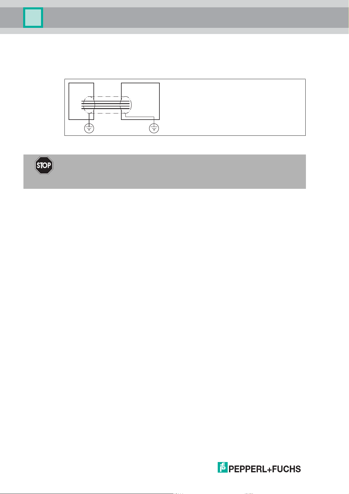
4.3.3 Handhelds
There are various handheld read/write devices available for controlling proces ses (write/read
functions, initialization of data carriers).
Figure 4.1
Handheld Frequency range
IPT-HH20 125 kHz
IST-HH20 250 kHz
IQT1-HH20 13.56 MHz
IC-HH20-V1 depending on the read/write head
12
2014-02
Page 13

IC-KP-B17-AIDA1
Link1
Link2
Traf fic
CH1 CH2 CH3 CH4
Control
IC-KP-B17-AIDA1
ESC
Product Description
4.4 Displays and Controls
The following displays and controls are located on the control interface.
LEDs
Description Function Statu s d es cri p tio n
CH1
CH2
CH3
CH4
PWR/ERR Statu s d i sp l ay fo r
Link1/Link2 Connection to the network
Tr a f fi c Network activity LED flashes green as soon as the IDENTControl
Statu s d i spl ay fo r t he
read/write heads
IDENTControl
for ch anne l 1/cha nnel 2
LED illuminates green as soon as there is an active
comm and on the read/write head.
LED illuminates yellow for approx. 1 second as
soon as a command is executed successfully.
LED illuminates green as soon as the
IDENTControl is connected to a power supply and
the interface is ready for operation .
LED illuminates red as soon as there is a hardware
error or a PROFINET name has been assigned and
no PROFINET connection has been established.
LED flashes green as soon as a signal has been
sent to the IDENTControl via the "Flashing"
PROFINET function or if there is an internal data
overflow.
LED is off until initial communication is made via
Ethernet.
LED illuminates green as soon as a connection to
the network is established.
sends data.
Display
Two-line multifunction display with 12 characters per line for displaying different status and
operating information and four pictograms for displaying connected reading heads.
Push buttons
Push buttons are used for controlling the display and selecting commands when programming
the control interface.
ESC
Return to higher level
Up menu item
Down menu item
2014-02
RETURN (confirm input)
13
Page 14
IC-KP-B17-AIDA1
+
A
-
+
-
B
1
2
3
4
5
1
5
3
2
4
PE
12345
signal
Protection earth
socket at housing read/write head trigger sensor trigger switch
voltage supply
TD+
TDRD+
not used
not used
RDnot used
not used
Ethernet
1 = + 24 V
2 = GND
3 =
not used
4 = not used
5 = not used
Product Description
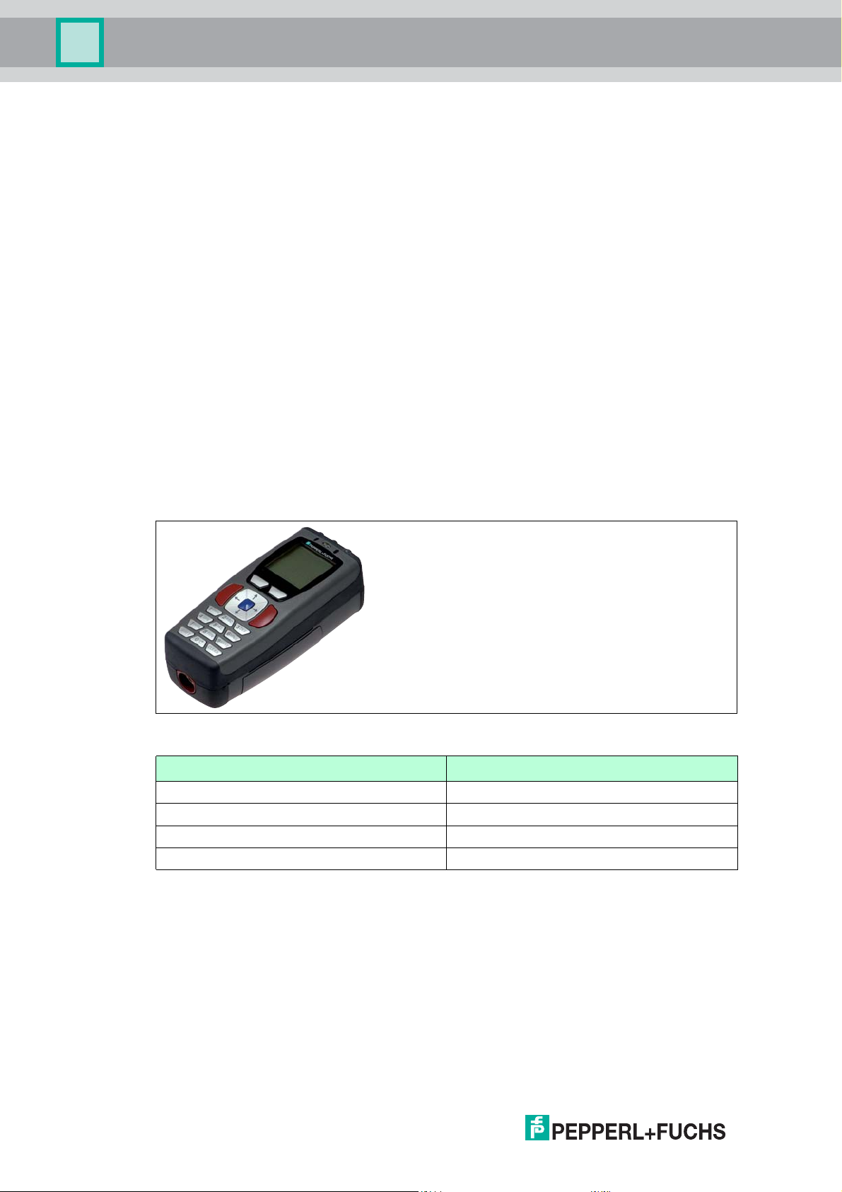
4.5 Interfaces and connections
The control interface IC-KP-B17-AIDA1 has the following interfaces and connections:
4.6 Delivery package
The delivery package contains:
■
1 IDENTControl control interface
■
1 quick start guide
■
1 grounding screw (already fitted)
■
1 serrated lock washer (already fitted)
■
2 crimp connectors (already fitted)
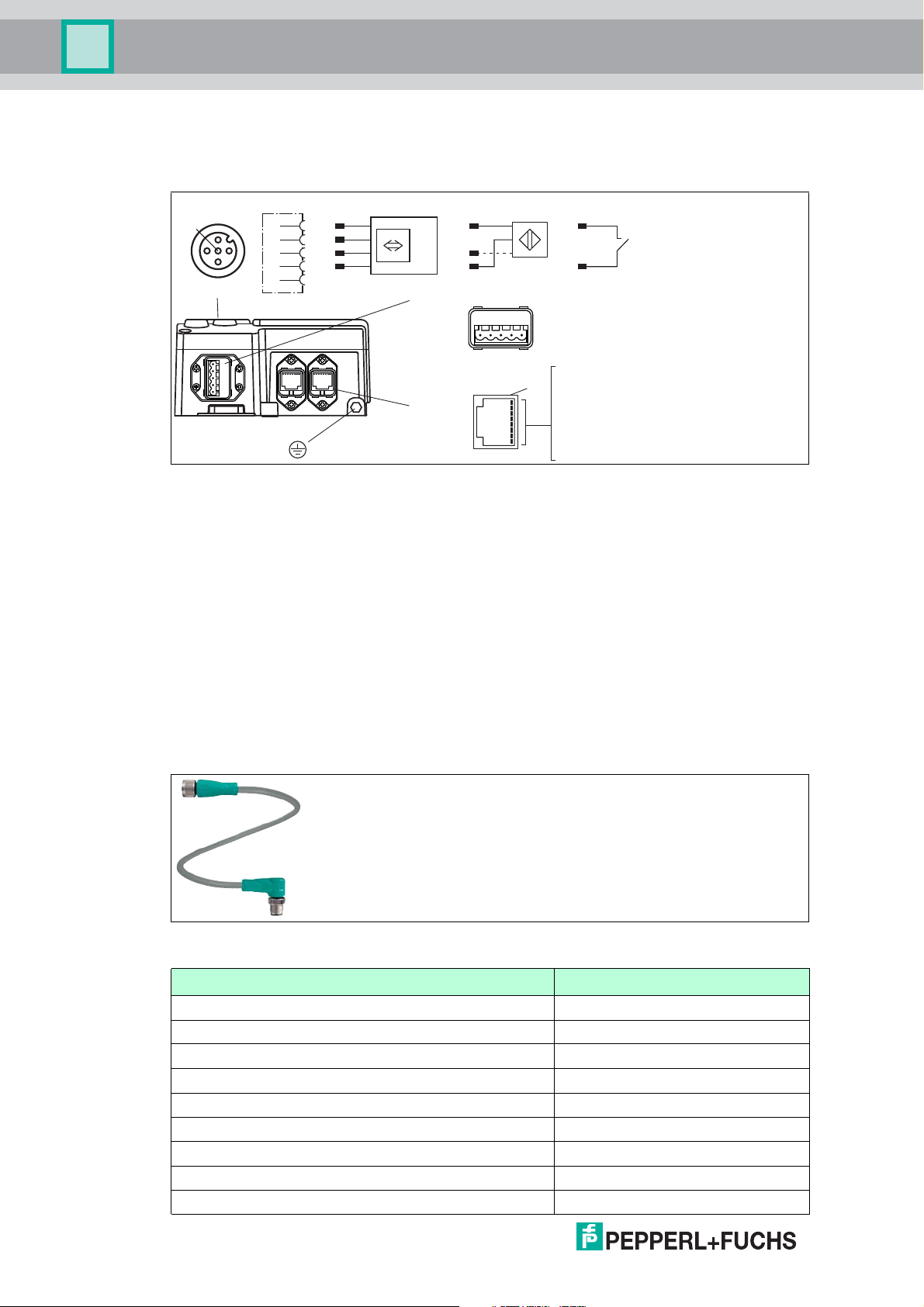
4.7 Connection accessories
4.7.1 Connection cable for R/W heads and trigger sensors
Compatible connection cables with shielding are available for connecting the R/W heads and
trigger sensors.
Figure 4.2
Accessories Description
2 m long (straight female, angled male) V1-G-2M-PUR-ABG-V1-W
5 m long (straight female, angled male) V1-G-5M-PUR-ABG-V1-W
14
10 m long (straight female, angled male) V1-G-10M-PUR-ABG-V1-W
20 m long (straight female, angled male) V1-G-20M-PUR-ABG-V1-W
Field attachable fema le c on nector, straig ht, shielded V1-G-ABG-PG9
Field attachable male connector, straight, sh ielded V1S-G-ABG-PG9
Field attachable fema le c on nector, angled, shielded V1-W-ABG-PG9
Field attachable male connector, angled, shielded V1S-W-ABG-PG9
Dummy plug M12x1 VAZ-V1-B3
2014-02
Page 15
IC-KP-B17-AIDA1
Product Description
4.7.2 Power Supply
The IDENTControl IC-KP-B17-AIDA1 is connected to the power supply via a connector that
complies with the AIDA directive.
Figure 4.3
Accessories Designation
Field attachable connector for power supply ICZ-AIDA1-MSTB
MSTB connecting cable to M12 connector ICZ-AIDA1-MSTB-0.2M-PUR-V1-G
MSTB connecting cable to open cable end ICZ-AIDA1-MSTB-5M-PUR
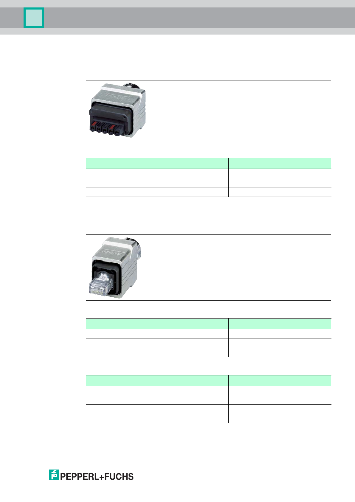
4.7.3 Network Cable to the Ethernet Interface
The IDENTControl IC-KP-B17-AIDA1 is connected to the network via a connector that
complies with the AIDA directive.
Figure 4.4
Accessories Designation
Field attachable connector for RJ45 ICZ-AIDA1-V45
RJ-45 connecting cable, D-coded to M12 ICZ-AIDA1-V45-0,2M-PUR-V1D-G
Stopping plugs ICZ-AIDA1-B
Connector Assignment
Signal Ma rking on con nector
TD+ Ye ll ow
TD- Orange
RD+ White
RD- Blue
2014-02
15
Page 16
IC-KP-B17-AIDA1
write head ControlIDENTControl
INTERBUS
Installation
5 Installation
5.1 Storage and transport
For storage and transport purposes, package the unit using s hockproof packaging material
and protect it against moisture. The best method of protection is to package the unit using the
original packaging. Furthermore, ensure that the ambient conditions are within allowable range.
5.2 Unpacking
Check the product for damage while unpacking. In the event of damage to the product, inform
the post office or parcel service and notify the supplier.
Check the package contents with your purchase order and the shipping documents for:
■
Delivery quantity
■
Device type and version in accordance with the type plate
■
Accessories
■
Quick start guide
Retain the original packaging in case you have to store or ship the device again at a later date.
Should you have any questions, please contact Pepperl+Fuchs.
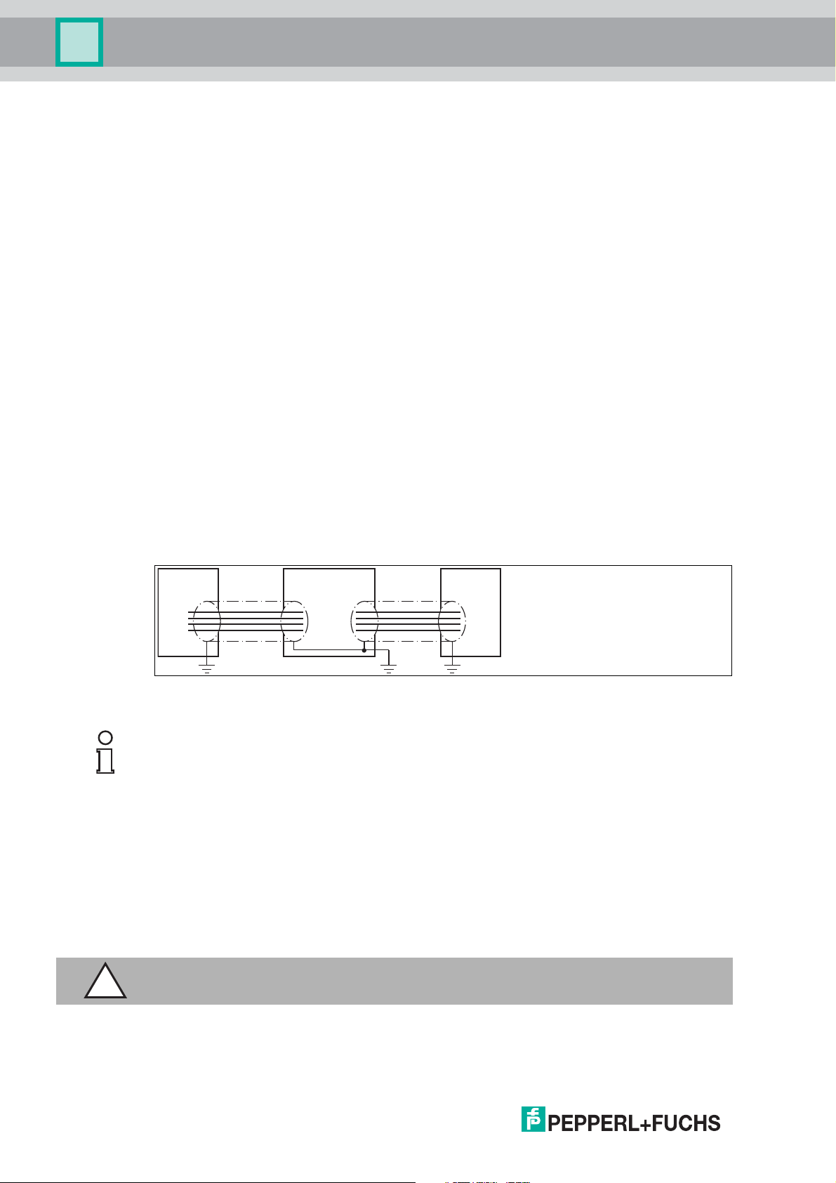
5.3 EMC concept
The outstanding noise immunity of the IDENTControl against emission and immission is based
on its consistent shielding design, which uses the principle of the Faraday cage. Interference is
caught in th e sh ie ld and sa fely diverted via the ground c onn ections.
The cable shielding is used to discharge electromagnetic interference. Wh en shielding a cable,
you must connect both sides of the shield to ground with low resistance and low inductance.
Note!
If cables with double shields are used, e.g. wire mesh and metalized foil, the both shields must
be connected together, with low resistance, at the ends when making up the cable.
Power supply cables are the source of much interference, e.g. from the supply lines of 3-phase
electric motors. For this reason, the parallel laying of power supply cables with data and signal
cables should be avoided, particularly in the same cable duct.
The metal enclosure of the IDENTControl and the metal enclosure of the R/W heads complete
the consistent shielding concept.
The most important issue here is that the shields are connected to ground with low resistance
and low inductance. The metal enclosure ensures that the shielding is not interrupted, i.e. the
complete electronics system and all routed cables are located within a Faraday cage.
Caution!
If you are operating the device in an Ethernet/IP network, read the connection guide.
16
2014-02
Page 17

IC-KP-B17-AIDA1
12345
trigger switch
trigger sensor
read/write head
signal
socket at housing
2
13
4
5
+
A
-
+
-
B
1
2
3
4
5
Installation
5.4 Device connection
Electrical connection using plug connectors makes installation simple.
5.4.1 Power supply
Connect the power supply for the IDENTControl using a connector that conforms with AIDA. A
plug with the following pin assignment is located on the housing:
1 + 24 V
2 GND
3 n.c.
4 n.c.
5 n.c.
Compatible connecting cable see chapter 4.7.2.
5.4.2 Read/Write Head and Trigger Sensors
A maximum of 4 read/write heads can be connected to the IDENTControl.
Instead of the read/write heads, a maximum of 2 trigger sensors can be connected to sockets 3
and 4. A trigger sensor can be assigned to only one read/write head. The trigger sensors must
be PNP.
Connect the read/write heads and trigger sensors to the sockets on the top of the enclosure
using M12 connectors.
For details of compatible read/write heads, see chapter 4.3.1 and of compatible connecting
cables, see chapter 4.7.1.
5.4.3 Cable length between control interface and R/W heads
The maximum cable length between the control interface and a connected R/W head is 1000
meters. If you wis h to attain the maximum possible ca ble length, select a suitably large ca ble
cross-section. See chapter 4.7.1
5.4.4 Ground connection
2014-02
Connect the IDENTControl interface to ground via a screw on the right under the housing.
Note!
In order to guarantee safe grounding, mount the serrated washer between the crimp connector
and the housing.
Use a ground conductor lead with a cross-section of at least 4 mm2.
17
Page 18
IC-KP-B17-AIDA1
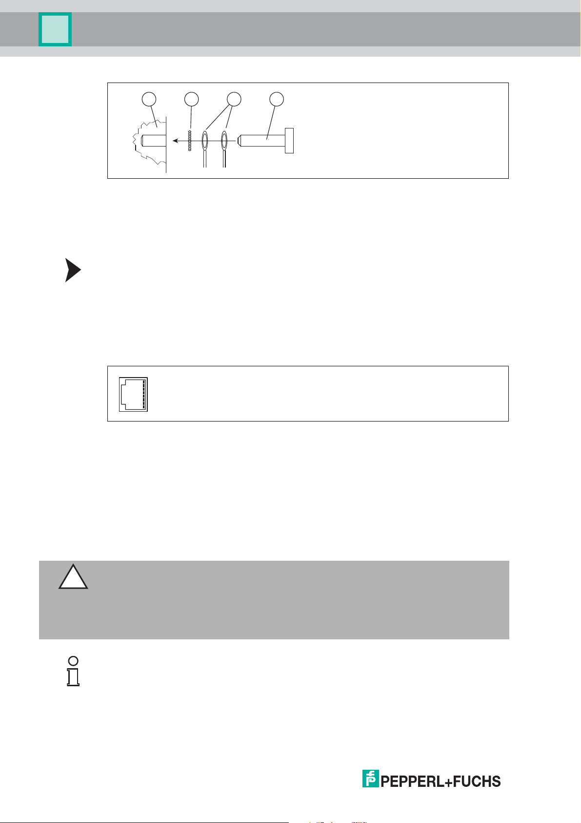
12 43
Installation
1 Housing
2 Serrated lock washer
3 Crimp connector
4 Lock screw
Connecting the IDENTControl to ground
Screw the ground conductor to the housing with a crimp connector.
5.4.5 Ethernet connection guide
Network connection
Connect the network to the IDENTControl using a connector that conforms with AIDA. Two
sockets with the following pin assignment are located on the housing:
■
TD+
■
TD-
■
RD+
■
Not used
■
Not used
■
RD-
■
Not used
■
Not used
Caution!
The network socket is connected galvanically to the grounded housing. The Ethernet/IP
specification does NOT require the use of Ethernet cables with a shield connected to the RJ-45
plug at both ends.
However, we recommend using cables with a continuous shield only, in order to avoid EMC
issues.
Note!
Protection degree IP67
If you use only one of the two network connections, you must close the unused network port
with the blind plug ICZ-AIDA1-B to achieve the protection degree IP67. The blind plug ICZAIDA1-B is available as an accessory.
See chapter 4.7.3.
18
2014-02
Page 19

IC-KP-B17-AIDA1
Installation
Transfer rates, line lengths and line types
The device can be operated in 10 Base-T or 100 Base-TX networks.
The maximum total line length is 100 m in both cases and only shielded network cables from
category 5 or above can be used.
Refer to the relevant chapter for information on compatible connecting cables.
2014-02
19
Page 20

IC-KP-B17-AIDA1
Commissioning
6 Commissioning
6.1 Preliminary considerations
Caution!
Uncontrolled triggered processes
Before commissioning the device, make sure that all processes are running smoothly;
otherwise damage may occur in the plant.
This manual contains important information required to operate the IDENTControl interface
with Ethernet interface. Due to the wide variety of programming options in an Ethernet network,
we a re unable to include exa mples relatin g to commissioning in this manu al.
One important aspect of the operation of an extended identification system on the Ethernet is
the time response of the overall system. The answer to the question "How long after the
positioning of a data carrier in front of a read/write head will the read data be available in the
com puter or P LC?" depends on many different factors.
The most important factors that determine the response time are:
■
Nature of the higher-level host system, e.g., PLC or PC
■
Communication betwe en th e client and server.
■
Network u tilization
■
Number and nature of connected read/write heads.
■
Code / data carrier types used
■
Nature of access to the communication objects of the read/write head.
■
Nature of the commands to the read/write head.
■
Structure of the user program.
If you are planning larger projects or gaining basic experience in programming an Ethernetbased sys tem, we recom mend constructing a model of your application before in stalling the
system in the plant. Use this model to test the process of data transfer to the identification
system.
6.2 Connection
Warning!
Incorrect electrical connection
Incorrect connections may damage the system .
Before commissioning, familiarize yourself with the system of communication between the
Ethernet controller and the read/write station. Check all connections before commissioning.
When the supply voltage is connected and the device is initialized, the "PWR/ERR" LED lights
up gree n. The LE D flashes green during in itialization. The LED lig h ts u p red if a device fault
occurs.a Profinet name is not assigned or there is no Profinet connection
20
2014-02
Page 21
IC-KP-B17-AIDA1
Commissioning
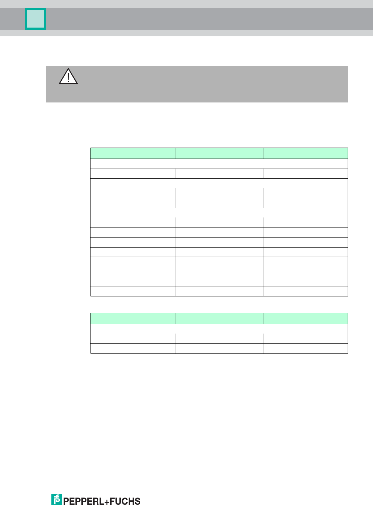
6.3 Device settings
Warning!
Device not configured or configured incorrectly
Configure the device prior to commissioning. A device that has not been configured or
configured incorrectly may lead to faults in the plant.
You must set the various parameters prior to comm issioning.
The parameters are volatile and non-volatile parameters. Volatile parameters are reset to their
default setting when the system is switched off and on again.
Non-volatile parameters
Para meters Default setting Va lue rang e
Ge n e r a l
Multiplex mode Off On / off
R/W head
Trigger mode Off On / off
Data carrier type 99 00 ... FF
Ethernet interface
MAC address 00:0D:81:xx:xx:xx 00:0D:81:xx:xx:xx
DHCP Off On / off
IP address 169.254.10.12 yyy.yyy.yyy.yyy
Stand ard ga te way 169.254.254.1 yyy.yyy.yyy.yyy
Subnet mask 255.255.0.0 yyy.yyy.yyy.yyy
Assembly inst. out 100d 100d ... 112d
PROFINET device name Empty Free text
Data hold time 50d x 10 ms 0d ... 255d x 10 ms
Volatile parameters
Para mete r Default setting Value rang e
R/W head
Password mode Off on / off
Password 00000000 00000000 ... FFFFFFFF
Configure the read/write station with the described system commands. "99" is preset as the
data carrier type.
2014-02
21
Page 22
IC-KP-B17-AIDA1
Version
information
IPH1 IPH2 IPH3 IPH4
IDENT
Control
IPH1 IPH2 IPH3 IPH4
IdentControl
Setting
IPH1 IPH2 IPH3 IPH4
Show System
Status
IPH1 IPH2 IPH3 IPH4
MultiplexM.
X
IPH1 IPH2 IPH3 IPH4
TagType
XX XX XX XX
IPH1 IPH2 IPH3 IPH4
Trigger Mode
XXX
IPH1 IPH2 IPH3 IPH4
TriggerState
CH3:x CH4:x
IPH1 IPH2 IPH3 IPH4
Reset to
Default
IPH1 IPH2 IPH3 IPH4
Setting
Channel
IPH1 IPH2 IPH3 IPH4
Activate
Command
IPH1 IPH2 IPH3 IPH4
Setting
Tagtype
IPH1 IPH2 IPH3 IPH4
Version
Channel No:
IPH1 IPH2 IPH3 IPH4
EnhancedRead
Fixcode
IPH1 IPH2 IPH3 IPH4
Channel
X
IPH1 IPH2 IPH3 IPH4
EnhancedRead
1 Word
IPH1 IPH2 IPH3 IPH4
Channel
X
IPH1 IPH2 IPH3 IPH4
Triggermode
IPH1 IPH2 IPH3 IPH4
Sensor Ch.
X
IPH1 IPH2 IPH3 IPH4
Quit
Command
IPH1 IPH2 IPH3 IPH4
Channel
X
IPH1 IPH2 IPH3 IPH4
Reset
IdentControl
IPH1 IPH2 IPH3 IPH4
Start Addres
XXXX
IPH1 IPH2 IPH3 IPH4
Channel
X
IPH1 IPH2 IPH3 IPH4
Channel
X
IPH1 IPH2 IPH3 IPH4
TagType
XX
IPH1 IPH2 IPH3 IPH4
Ch:1 Data
XX.XX.XX
IPH1 IPH2 IPH3 IPH4
MultiplexM.
XXX
IPH1 IPH2 IPH3 IPH4
Multiplex
Mode
IPH1 IPH2 IPH3 IPH4
Proceed
with Return
IPH1 IPH2 IPH3 IPH4
Ident Ch.
X
IPH1 IPH2 IPH3 IPH4
Triggermode
X
IPH1 IPH2 IPH3 IPH4
Command
executed
IPH1 IPH2 IPH3 IPH4
Starting
System
IPH1 IPH2 IPH3 IPH4
Commissioning
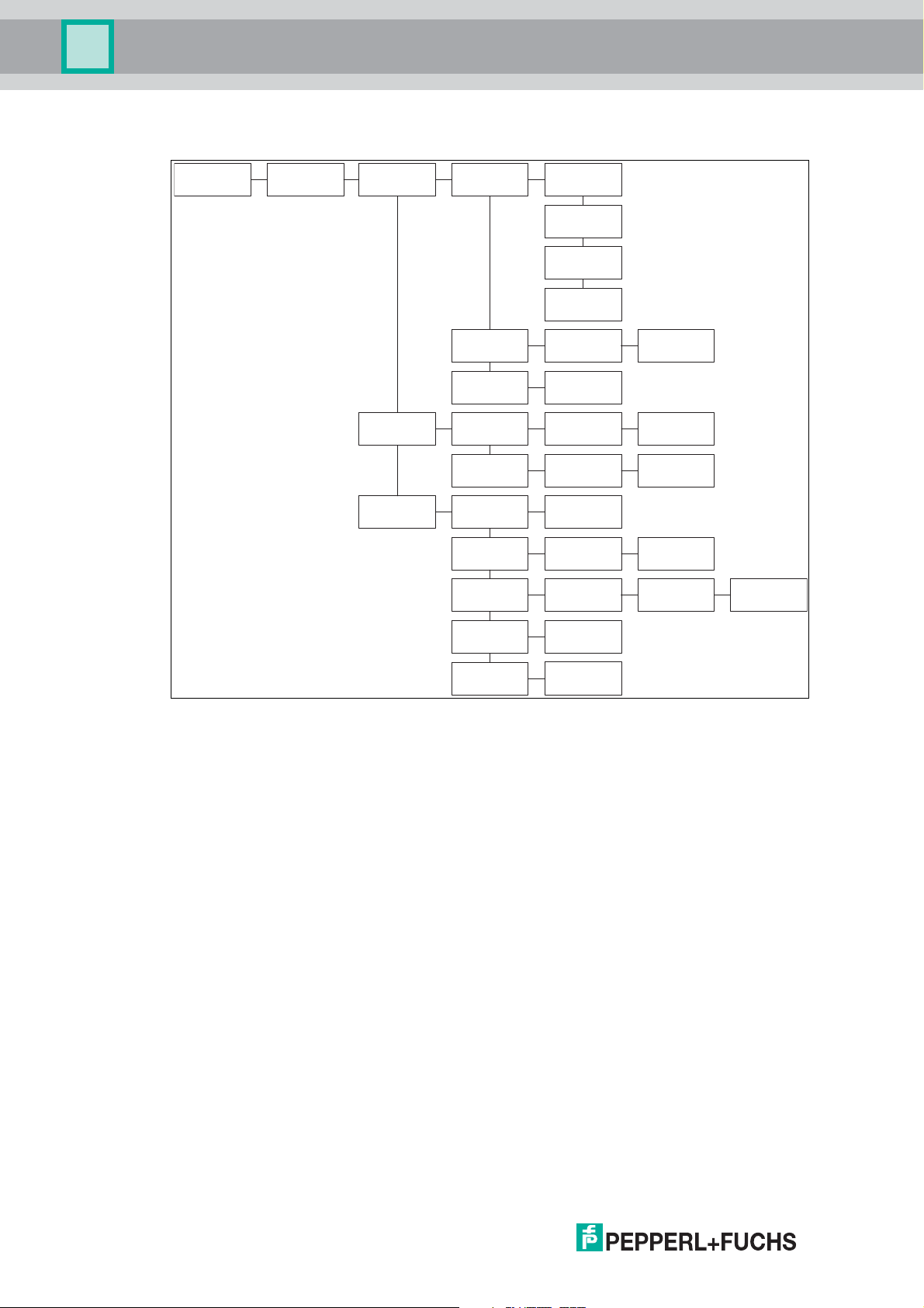
6.4 Operating the device
22
Figure 6. 1 Bedienung am Gerät Teil 1
2014-02
Page 23
IC-KP-B17-AIDA1
Version
information
IPH1 IPH2 IPH3 IPH4
IDENT
Gateway
IPH1 IPH2 IPH3 IPH4
Setting
Display
IPH1 IPH2 IPH3 IPH4
Setting
Language
IPH1 IPH2 IPH3 IPH4
LCD light
on/off
IPH1 IPH2 IPH3 IPH4
LCD Contrast
Setting
IPH1 IPH2 IPH3 IPH4
LCD Default
Settinfg
IPH1 IPH2 IPH3 IPH4
Setting
XXXXX
IPH1 IPH2 IPH3 IPH4
LCD Kontrast
XX
IPH1 IPH2 IPH3 IPH4
Set
BUS Address
IPH1 IPH2 IPH3 IPH4
Setting
Network
IPH1 IPH2 IPH3 IPH4
Setting
IPH1 IPH2 IPH3 IPH4
Setting
IP-Address
IPH1 IPH2 IPH3 IPH4
Setting
Subnet mask
IPH1 IPH2 IPH3 IPH4
StandardGateway
IPH1 IPH2 IPH3 IPH4
Display
MAC Adresse
IPH1 IPH2 IPH3 IPH4
DHCP
off
IPH1 IPH2 IPH3 IPH4
IP XXX.XXX.
XXX.XXX
IPH1 IPH2 IPH3 IPH4
SM XXX.XXX.
XXX.XXX
IPH1 IPH2 IPH3 IPH4
SG XXX.XXX.
XXX.XXX
IPH1 IPH2 IPH3 IPH4
Mac XX:XX:XX
XX:XX:XX
IPH1 IPH2 IPH3 IPH4
Setting
ProfinetIO
IPH1 IPH2 IPH3 IPH4
Device-
IPH1 IPH2 IPH3 IPH4
XXXXX
IPH1 IPH2 IPH3 IPH4
Datahold
Time
IPH1 IPH2 IPH3 IPH4
Data hold
XXX x 10 ms
IPH1 IPH2 IPH3 IPH4
Setting
Ethernet/IP
IPH1 IPH2 IPH3 IPH4
Assembly
IPH1 IPH2 IPH3 IPH4
Out XXX In XXX
IPH1 IPH2 IPH3 IPH4
Datahold
Time
Instance
IPH1 IPH2 IPH3 IPH4
Data hold
XXX x 10 ms
IPH1 IPH2 IPH3 IPH4
Reset?
X
IPH1 IPH2 IPH3 IPH4
Reset?
X
IPH1 IPH2 IPH3 IPH4
Reset?
X
IPH1 IPH2 IPH3 IPH4
Reset?
X
IPH1 IPH2 IPH3 IPH4
Reset?
X
IPH1 IPH2 IPH3 IPH4
Reset?
X
IPH1 IPH2 IPH3 IPH4
Reset?
X
IPH1 IPH2 IPH3 IPH4
DHCP
Speed and
Duplexmode
IPH1 IPH2 IPH3 IPH4
Automatic
Detection
IPH1 IPH2 IPH3 IPH4
Reset?
X
IPH1 IPH2 IPH3 IPH4
name
IDENT
Control
IPH1 IPH2 IPH3 IPH4
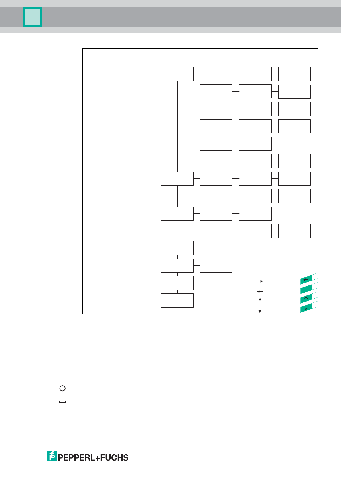
name
stands for pressing
ESC
stands for pressing
stands for pressing
stands for pressing
Direction
Direction
Direction
Direction
Commissioning
6.5 Setting the IP address
2014-02
Figure 6.2 Bedienung am Gerät Teil 2
The IP address of the IDENTControl is preset to 169.254.10.12. The way in which the IP
address is modified depends on if you are using a DHCP server.
If you are not using a DHCP server the IP address is assigned manually: You preset the IP
address on the web page or via the function keys. The device can be addressed via the preset
IP address.
Note!
You can reset the device to the preset IP address by pressing the "ESC" and "Return" buttons
simu ltaneously when switchin g o n the dev ice un til the P W R/ERR LED lights up p erm anently.
If you are using a DHCP server (or operating via a PROFINET) the server assigns the IP
address to the IDENTControl.
23
Page 24

IC-KP-B17-AIDA1
Commissioning
If you intend to use a DHCP server, you must select the "Use DHCP" option on the web page.
See chapter 8.2
Note!
We recommend using a fixed preset IP address in order to avoid system malfunctions.
6.5.1 Using the identification system without a DHCP server
The following parameters must be set manually on the web page.
■
DHCP-OFF
■
IP address
■
Subnet mask
■
Gateway address
■
Assembly inst. Out
■
PROFINET device name
■
Data hold time
1)
: Parameters can also be set manually via the display.
1)
1)
1)
1)
1)
1)
Caution!
Always use parameters that you know are compatible with your network.
See chapter 8.2.
6.5.2 Using the identification system in conjunction with a DHCP server
In this case, the parameters of a DHCP server are assigned to the identification system.
However, if an IP address is not assigned to the device, the corresponding settings on the
DCHP server must be configured accordingly.
The identification system ignores the permanent IP address, subnet mask and gateway
address parameters preset in the device.
24
2014-02
Page 25
IC-KP-B17-AIDA1
Command
Control IDENT Control
* in case of an "enhanced" command
Confirmation
(Status FFh)
Response
(Execution Status)
Response *
(Execution Status)
Commands
7 Commands
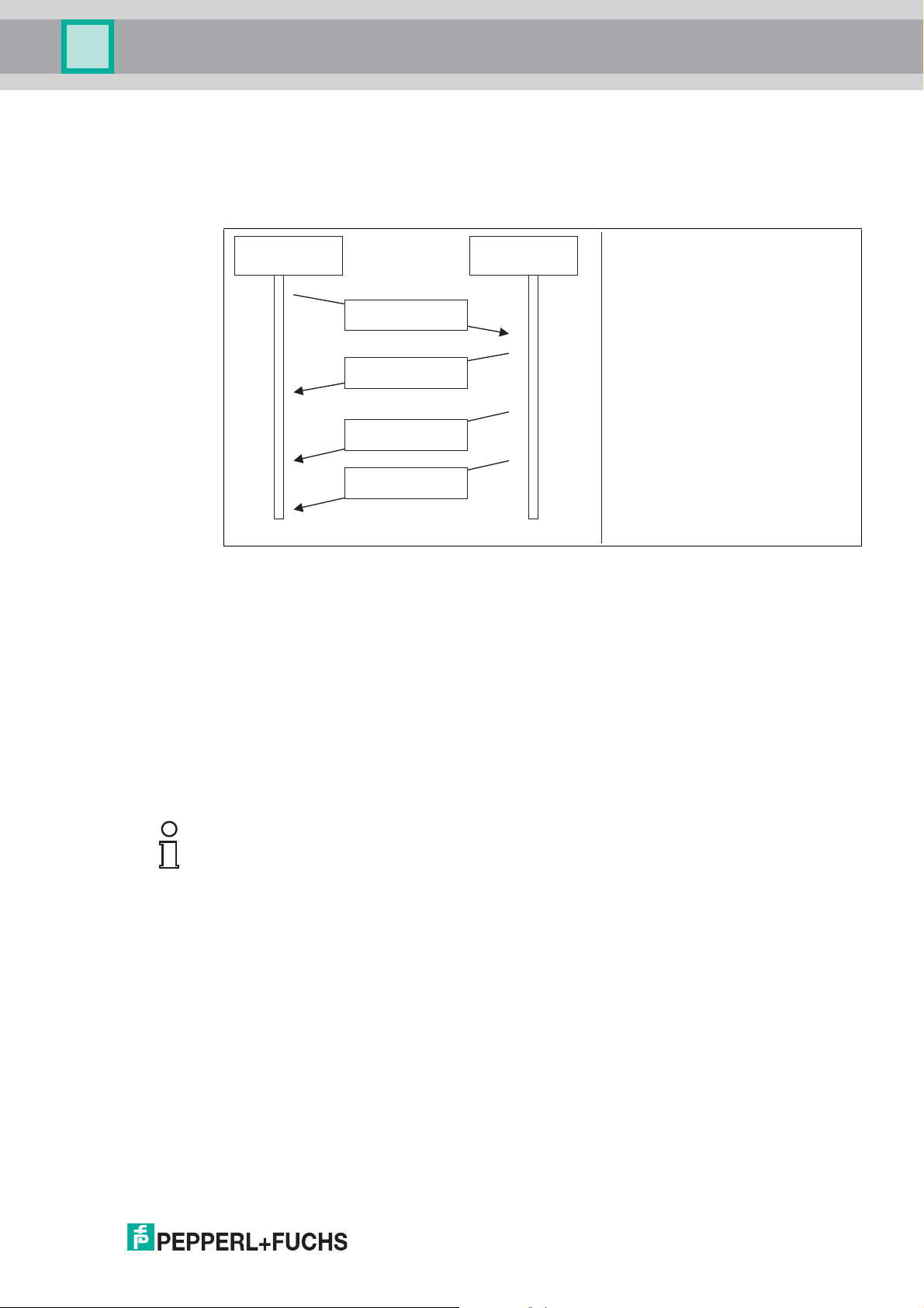
7.1 Data Exchange
The transferred data is composed of command, confirmation and response telegrams.
The control software (client) sends a command to the IDENTControl (server). The
IDENTControl then sends confirmation of receipt (not with MODBUS TCP/IP). The
IDENTControl sends the response after the command is executed.
The IDENTControl can send multiple responses for enhanced commands. However, only a
single confirmation is sent.
A command consists of the telegram length (TCP/IP und MODBUS TCP/IP only), the
command code, the channel associated with the read/write head (ident channel), a specified
number of parame te rs and the data relatin g to the com man d.
The confirmation consists of the telegram length (TCP/IP and MODBUS TCP/IP only), the echo
of the command code, the echo of the ident channel, the status FFh and the reply counter.
The response consists of the telegram length (TCP/IP and MODBUS TCP/IP only), the echo of
the command code, the ident channel, the status, the reply counter and the requested data.
Note!
Power Supply Reset
The IDENTControl communicates via one of the following protocols:
■
TCP/IP
■
MODBUS TCP
■
Ethernet/IP
■
PROFINET IO
The Java applet of the IDENTControl web function also uses the TCP/IP protocol. To change
the protocol that the IDENTControl uses to communicate, reset the power supply.
2014-02
25
Page 26

IC-KP-B17-AIDA1
Control software
Client
IC-KP-...
(Server)
Connection
on TCP/IP level
Connection
on TCP/IP level
Data exchangeData exchange
Disconnection
on TCP/IP-level
Disconnection
on TCP/IP-level
Commands
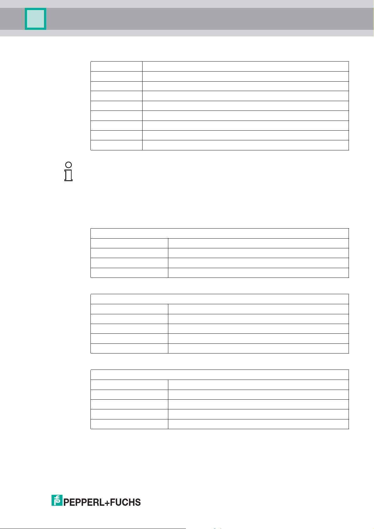
7.2 Communication via TCP/IP
7.2.1 General information on data communication via TCP/IP
The IC-KP-B17-AIDA1 device was designed to act as a TCP/IP server, which means that the
so-called client must send a command to actuate each function.
Communication is established via the TCP port 10000. Programming control software requires
accurate knowledge of TCP/IP sockets.
The following illustration shows the basic communication flow:
A connection must be established on the TCP/IP level before data can be exchanged. From this
point onwards, commands can be sent from the client to the IC-KP-B17-AIDA1 device.
Command:
Byte 0 Telegram length, high byte [(N+1) div 256]
Byte 1 Telegram length, low byte [(N+1) mod 256]
Byte 2 Command code
Byte 3 Channel / Toggle bit = 0
Byte 4 Parameter
Byte 5 Parameter
Byte 6 Write data
... ...
Byte N Write data
Confirmation:
Byte 0 Telegram length, high byte 0
Byte 1 Telegram length, low byte 6
Byte 2 Command code (echo)
Byte 3 Channel / Toggle bit (echo) = 0
Byte 4 Status FFh
Byte 5 Reply counter
26
2014-02
Page 27
IC-KP-B17-AIDA1
Commands
Response:
Byte 0 Telegram length, h ig h b yte [(N+ 1) div 256]
Byte 1 Telegram length, low byte [(N+1) mod 256]
Byte 2 Command code (echo)
Byte 3 Channel / Toggle bit = 0
Byte 4 Status
Byte 5 Reply counter
Byte 6 Read data
... ...
Byte N Read data
Note!
The toggle bit is not required for TCP/IP.
7.2.2 Command examples TCP / IP
Example 1: Preset tag type using the change tag command
Command: Change tag type on channel 1 to IPC03.
00:06:04:02:30:33 (hexadecimal format)
00:06 Telegram length (6 bytes)
04 Command code (CT)
02 Reserved / Channel (l), toggle bit (0)
30:33 Tag ty p e (I PC 0 3)
Confirmation
00:06:04:02:FF:01
00:06 Telegram length (5 bytes)
04 Repeat command code (CT)
02 Reserved / Channel (l), toggle bit (0)
FF Status FFh (processing command)
01 Reply counter
Response: There is a type IPH-... read/write head on channel 1.
00:06:04:02:00:02
00:06 Telegram length (6 bytes)
04 Repeat command code (CT)
02 Reserved / Channel (l), toggle bit (0)
00 Status 0 (comm and was executed without error)
02 Reply counter
2014-02
27
Page 28

IC-KP-B17-AIDA1
Commands
Alternative response: There is no head on channel 1.
00:06:04:02:06:02
00:06 Tel e g ra m l en gt h ( 6 b y te s)
04 Repeat command code (CT)
02 Reserved / Channel (l), toggle bit (0)
06 Status 6 (hardware error)
02 Reply counter
Example 2: Read tag using the single read command
For this command example, it is assumed that
■
th e tag type IP C03 i s set.
■
one type IPH-… read head is connected to channel 1.
Command: Read two words from address 0 on channel 1.
00:06:10:22:00:00
00:06 Tel e g ra m l en gt h ( 6 b y te s)
10 Command code (SR)
22 Word number (2) / Channel (1), toggle bit (0)
00:00 Word address (0000)
Confirmation
00:06:10:22:FF:01
00:06 Tel e g ra m l en gt h ( 6 b y te s)
10 Repeat command code (SR)
22 Word number (2) / Channel (1), toggle bit (0)
FF Status FFh (processing command)
01 Reply counter
Response: A type IPC03 tag is located in front of the read head. The highlighted part is
the content of the tag.
00:0E:10:22:00:02:31:32:33:34:35:36:37:38
00:0E Telegram length (14 bytes)
10 Repeat command code (SR)
22 Word number (2) / Channel (1), toggle bit (0)
00 Status 0 (comm and was executed without error)
02 Reply counter
31:32:33:34:35:36:37:38 Data
Alternative response: No tag in front of the read head.
00:06:10:02:05:02
00:06 Tel e g ra m l en gt h ( 6 b y te s)
10 Repeat command code (SR)
02
05 Statu s 5 (no tag in the detection rang e )
02 Reply counter
Tab le 7 . 1
1)
: No data in the telegram
Word number (0)1) / Channel (1), toggle bit (0)
2014-02
28
Page 29

IC-KP-B17-AIDA1
Commands
7.3 Communication via MODBUS TCP/IP
7.3.1 General Information on Data Communication via MODBUS/TCP
Data is exchanged between a MODBUS master (controller) and a MO DBUS slave
(identification system) by reading and writing registers. The slave contains read and write
registers. Data exchange is always initiated by the master. The master initiates an identification
system function by transferring an identification command to the write register. The master can
then retrieve the response via the read registers. The functions read holding registers, write
multiple registers and read/write multiple registers are available for this purpose on the ICKP-B17-AIDA1 device. MODBUS communication occurs via port 502. The terms "input
register" and "output register" are defined from a PLC perspective.
7.3.2 Overview of the characteristics of the integrated MODBUS slave
■
Multimaster c apa bility.
■
Data exchange using the commands read holding registers, write multiple registers
and read/write multiple registers.
■
Each channel is assigned a separate register area so that different controllers can each
adopt a R/W head. Only one master has write permissions for each register area.
■
The output register data is stored temporarily in a FIFO memory.
■
A monitor master can also read the data from the identification system.
■
The same identification commands used with TCP/IP are also used here.
Multimaster capability
The device can communicate with several masters. An ident channel can be addressed by two
masters. The first ma ster is the control master and addresses the device using device ID 1.
This master possesses both write and read permissions. Another master can be used to read
the data and is a protocolling master. This master then addresses the device using device ID 2.
The device can therefore be addressed on each channel once using device ID 1 and once
using device ID 2. If another master attempts to address the device on the same channel,
access to this channel is denied. A maximum of ten m asters can communicate with the device
at any one time.
MODBUS commands
The device supports the comma nds read holding registers, write multiple registers and
read/write multiple registers.
2014-02
29
Page 30
IC-KP-B17-AIDA1
Channel 0
(IDENTControl)
Channel 1
Channel 2
Channel 3
Channel 4
Group 1 Group 2 Group 3
0
122
0
124
0
124
3
2
3
2
1000
1122
3
2
3
2
1000
1124
1000
1124
2000
2122
3
2
3
2
2000
2124
2000
2124
3000
3122
3
2
3
2
3000
3124
3000
3124
4000
4122
3
2
3
2
4000
4124
4000
4124
Commands
Division of the register
The device contains four ident channels and a configuration channel. Each channel is
assigned a separate register area
so that a single master addresses all channels or a separate master addresses each individual
channel.
The following three register groups are assigned to each channel:
1. Group 1: Output register (device ID 1)
2. Group 2: FIFO input register (device ID 1)
3. Group 3: FIFO monitor register (device ID 2)
30
2014-02
Page 31

IC-KP-B17-AIDA1
Commands
Application example
Example 1:
Group 1 Group 2 Group 3
Channel 0
(IDENTControl)
Channel 1
Channel 2
Channel 3
Channel 4
122
1000
1122
2000
2122
3000
3122
4000
4122
2
3
0
124
1000
1124
2000
2124
3000
3124
4000
4124
0
2
3
2
3
2
3
2
3
124
1000
1124
2000
2124
3000
3124
4000
4124
2
3
0
2
3
2
3
2
3
2
3
Controlling Logging
MasterMaster
Description:
A master communicates with all channels. Optionally, an additional master can be used to log
data communication between the controlling master and the identification system.
2014-02
31
Page 32

IC-KP-B17-AIDA1
Channel 0
(IDENT Control)
Channel 1
Channel 2
Channel 3
Channel 4
Group 1 Group 2 Group 3
0
122
0
124
0
124
3
2
3
2
1000
1122
3
2
3
2
1000
1124
1000
1124
2000
2122
3
2
3
2
2000
2124
2000
2124
3000
3122
3
2
3
2
3000
3124
3000
3124
4000
4122
3
2
3
2
4000
4124
4000
4124
Controlling
Logging
Master 4
Master 4
Controlling
Logging
Master 3
Master 3
Controlling
Logging
Master 2
Master 2
Controlling
Logging
Master 1
Master 1
Controlling
Logging
Master 0
Master 0
Controlling
Logging
Master 5
Master 5
Commands
Example 2:
Description:
One controlling and one protocolling master are used for each channel. A protocolling master
can also access channels here.
Dual access to a register group within one channel is never permitted.
Group 1: Output register
Each area of this group is divided as follows:
Address
(0-based,
decimal)
0 + K - Reserved
1 + K Byte 0 Telegram length, h ig h byte [(N+ 1) div 256]
2 + K Byte 2 Command code
I + K Byte N-1 Parameters
Table 7.2 Output register
K = 0, 1000, 2000, 3000, 4000
I = 3, 4, 5...
If the deletion bit is set, all data stored in the FIFO of the relevant channel (defined by K) is
deleted. The delete operation only starts if the status of the deletion bit changes from 0 to 1.
Byte number of the
Use
identification telegram
- Reserved/Deletion bit (LSB)
Byte 1 Telegram length, low byte [(N+1) mod 256]
Byte 3 Reserved/Toggle bit
Byte N Parameters
2014-02
32
Page 33

IC-KP-B17-AIDA1
Commands
Groups 2 and 3: FIFO input register and FIFO monitor input register
Each area of these groups is divided as follows:
Address
(0-based,
decimal)
0 + K - Reserved
1 + K Byte 0 Telegram length, high byte [(N+1) div 256]
2 + K Byte 2 Command code (Echo)
3 + K Byte 4 Statu s
I + K Byte N-1 Data
Table 7.3 FIFO input re gister and F IFO m onitor input register
K = 0, 1000, 2000, 3000, 4000
I = 4, 5, 6...
Utilization indicates the percentage of the FIFO memory occupied by data that ha s not been
retrieved. If the response data of the device is retrieved at a lower rate than the response data is
generated, the FIFO memory overflows, which results in a loss of data. Therefore, make sure
that a sufficiently high polling rate is set to ensure that the utilization value remains as far below
15 % as possible.
Byte number of the
identification telegram
- Utilization A
Byte 1 Telegram le ngth, low b yte [(N+1) mod 25 6]
Byte 3 Reserved/Channel/Toggle bit
Byte 5 Re ply counter
Byte N Data
Use
Utilization value Meaning
0 No data available
1 .. 100 Data available
101 Data available, but data lost due to FIFO overflow
Table 7.4 Utilization value and occupancy of the FIFO memory in percent
FIFO memory
The input data of each channel is stored in two FIFO memories with identical structures. Each
FIFO memory is composed of 32 elements.
The utilization of a FIFO memory is indicated in the first register of the relevant channel. When
registers are read from the memory, the channel content in the memory is shifted along one
memory element. A master can therefore read data from the memory only once.
A protocolling master addresses the device using device ID 2. The protocolling master only has
read permissions for the third group.
7.3.3 Supported MODBUS commands
write multiple registers (10h)
This MODBUS command (request) is used to start system commands and read/write
commands. The device sends a response to a write multiple registers command as outlined
in the MODBUS specification. In the event of a fault, a corresponding response is issued with
an exception code.
Process:
2014-02
33
Page 34

IC-KP-B17-AIDA1
Commands
1. A request is issued. Th e followin g pa rameters mus t be known here:
Start address (depending on channel) Channel 0 0d
Number of registers to be written: Maximum 123d
Table 7.5 Required request parameters
2. The identification system sends a response to the MODBUS master. If an error occurs, the
response contains an exception code. A write command must be executed from the first
address from the respective channel.
If an identification command is initiated several times (e.g., if you wish to execute a read
command several times in succession), the first four bytes of the identification telegram must
be modified accordingly. The toggle bit can be used for this.
Example:
Channel 1 1000d
Channel 2 2000d
Channel 3 3000d
Channel 4 4000d
In the following example, the tag type IPC03 is set to channel 2 and then a read command is
executed. The following prerequisites must be fulfilled:
■
One type IPH-XX read head is connected to channel 2.
■
The IP address is configured.
■
A network connection is established.
■
A MODBUS master is available (PC-based or PLC).
First step
The following parameter settings must be configured in the MODBUS master:
Slave IP address: Identification system IP address
Timeout time: 1000 ms
Device ID: 1
Start address: 2000d
Number of registers to be written. 4d
Table 7.6 Required parameter settings on the MODBUS master
34
2014-02
Page 35

IC-KP-B17-AIDA1
Commands
Second step
The identification command change tag must be sent to the identification system to set the tag
type.
Address
(0-based)
2000d High byte Reserved 00h -
2001d High byte
2002d High byte
2003d High byte
Table 7.7 Required parameter settings for the data carrier type
The slave must confirm that the executed MO DBUS transaction was successful. If this is not
the case, the master generates an error message.
Register division
By te number of th e
identification
telegram
Low byte Reserved/Deletion bit
Byte 0
Low byte
Byte 1
Byte 2
Low byte
Byte 3
Byte 4
Low byte
Byte 5
Use Contents Meaning
(LSB)
Length of the identification telegram from this
byte onwards
Length of the
identification telegram
Command code 04h change tag
Reserved/Channel/
Toggle bit
Data carrier type
High byte
Data carrier type
Low byte
00h No delete operation
00h -
06h 6 bytes long
command
00h No channel
specification requ ired
30h IPC03
33h IPC03
Third step
In this example, the read command is initiated by the identification command enhanced read .
Address
(0-based)
2000d High byte Reserved 00h -
2001d High byte
2002d High byte
2003d High byte
2014-02
Table 7.8 Executing the read comma nd
Register division
Byte nu mber of th e
identification
telegram
Low byte Reserved/Deletion bit
Byte 0
Low byte
Byte 1
Byte 2
Low byte
Byte 3
Byte 4
Low byte
Byte 5
Use Contents Meaning
(LSB)
Length of the
ide ntification telegram
from this byte onwards
Length of the
ide ntification
telegram
Command code 19h enhanced read
Word number/Channel/
To gg le bit
Word address
High byte
Word address
Low byte
00h No delete operation
00h -
06h 6 bytes long
command
40h Read 4 words, no
ch annel specification
required
00h Rea d from data carrier
address 0
00h Same as previous
byte
35
Page 36

IC-KP-B17-AIDA1
Commands
Note!
When all 3 steps have been completed successfully, LED 2 under the display mu st light up
green. If you then hold a type IPC03 data carrier in front of the reading head, the LED should
light up orange. If you wish to transfer an identification command to the identification system a
second time, the toggle bit must be inverted to enable the transfer of cyclic data to a PLC.
read holding registers (03h)
This MODBUS command (request) can be used to export the input register from the
identification system. When data becomes available, the device writes it to the input register. If
the data is not retrieved immediately, up to 32 responses can be stored temporarily before data
is lost. If no response data is available, the content of the register is 0.
Process:
1. A request is issued. Th e followin g pa rameters mus t be known here:
Start address (depending on channel) Channel 0 0d
Number of registers to be read: Maximum 125d
Table 7.9 Parameters required for a request
Channel 1 1000d
Channel 2 2000d
Channel 3 3000d
Channel 4 4000d
2. The identification system sends a response to the MODBUS master. This response includes
the content of the requested register. If an error occurs, the response contains an exception
code. A read/write command mus t be executed from the first address of the relevant channel.
Example:
In this example, the responses generated in the previous example are retrieved. The following
prerequisite must be fulfilled:
■
The example of the write multiple registers was executed successfully.
First step
The MODBUS master parameters must be configured:
Slave IP address: Identification system IP address
Timeout time: 1000 ms
Device ID: 1
Start address: 2000d
Number of registers to be read: 12d
Table 7.10 MODBUS ma ster parameters
Second step
A read holding registers MODBUS command must be executed. The contents of the register
indicate the response to the executed iden tification command change tag.
36
2014-02
Page 37

IC-KP-B17-AIDA1
Commands
Address
(0-based)
2000d High byte Reserved 00h -
2001d High byte
2002d High byte
2003d High byte
2004d 2011d
Table 7.11 Responses to the executed identification command change tag
Register division
Byte nu mber of th e
identification
telegram
Low byte Utilization register 06h 6% of the FIFO
Byte 0
Low byte
Byte 1
Byte 2
Low byte
Byte 3
Byte 4
Low byte
Byte 5
High byte - 00h -
Low byte - 00h -
Use Contents Meaning
Length of the
ide ntification
telegram from this byte
onwards
Length of the
ide ntification
telegram
Command code 04h change tag
Reserved/Channel/
To gg le bit
Statu s 00h 00h = com mand
Reply counter 01h Increases by 1 after
00h -
06h 6 bytes long
04h 4 corresponds to
memory is utilized
command
channel 2. Channel
number shifted 1 bit to
the left.
executed (meaning of
the identification
statuses see chapter
10.1)
each additional
response.
Third step
A read holding registers - MODBUS command must be executed. The registers contain the
response to the executed identification command enhanced read.
Address
(0-based)
2000d High byte Reserve d 00h -
2001d High byte
2014-02
Register division
Byte number of the
identification
telegram
Low byte Utilization regis te r 03h 3% of the FIFO
Byte 0
Low byte
Byte 1
Use Contents Meaning
memory is utilized
Length of the
identification
telegram from this byte
onwards
Length of the
identification
telegram
00h -
06h 6 bytes long
37
Page 38

IC-KP-B17-AIDA1
Commands
Address
(0-based)
2002d High byte
2003d High byte
2004d 2011d
Table 7.12 Response to the executed identification command enhanced read
Register division
Byte number of the
ide ntification
telegram
Byte 2
Low byte
Byte 3
Byte 4
Low byte
Byte 5
High byte Data 00h No d ata read beca use
Low byte Data 00h No d ata r ead beca use
Use Contents Meaning
Command code 19h enhanced read
Word number/Channel/
To gg le b it
Status 05h 05h = identification
Reply counter 02h Increases by 1 after
04h Word count = 0.
command
4 corresponds to
channel 2. Channel
number shifted 1 bit to
the left.
read error (meaning of
the identification
statuses see chapter
10.1)
each additional
response.
no data carrier in front
of the read head.
no data carrier in front
of the read head.
Note!
If a type IPC03 data carrier is held in front of the reading head, the data can be viewed if a read
holding registers command is executed repeatedly.
read/write multiple registers (17h)
This MODBUS command combines the functionality of the read holding registerscommand
with the write multiple registerscommand. This command should always be used when data
is exchanged cyclically via a controller. The following should be noted:
If an identification command is initiated via this MODBUS command (for example, a read
command), the answer to this command is not included in the response associated with this
request. The data is only available after the time required to process the command has
elapsed.
If an identification command is initiated several times (e.g., if you wish to execute a read
command several times in succession), the first four bytes of the identification telegram must
be modified accordingly. The toggle bit can be used for this.
Process:
1. A request is issued. Th e followin g pa rameters mus t be known here:
Writing:
Start address (depending on channel) Channel 0 0d
Channel 1 1000d
Channel 2 2000d
Channel 3 3000d
Channel 4 4000d
Number of registers to be written: Maximum 121d
Table 7.13 Parameters required for a request
2014-02
38
Page 39

IC-KP-B17-AIDA1
Commands
Reading:
Start address Writing start address
Number of registers to be read: Maximum 125d
Table 7.14 Parameters required for a request
2. The identification system sends a response to the MODBUS master. If an error occurs, the
response contains an exception code.
7.3.4 General notes on creating the control program
TCP connection:
Many MODBUS masters enable the use of transactions accompanied by a TCP link
connection and disconnection. As outlined in the MODBUS specification, we recommend
maintaining as opposed to terminating the connection following a transaction.
Tr an s a c t io n tim e o u t :
The timeout time heavily influences the load on the network you are using. 1000 ms can be
accepted as a guide value.
Transaction cycle time:
The repeat rate must be higher than the number of data carriers read per time unit (per
channel). A correspondingly short cycle time must be selected. The FIFO load register can be
monitored to determine whether the refresh rate of the controller is sufficiently high.
Cyclic reading and writing of registers:
Writing:
An identical identification command can only be executed again in succession if the first four
telegram bytes change. The toggle bit can be used for this. In this way, the controller can
transfer a register set several times during a cyclic data exchange without issuing a second
identification command unintentionally.
All identification commands contain a channel number. This is ignored when MODBUS/TCP is
used. The channel is defined using the register address only. The ident channel is still included
in the telegram when the register is read.
Reading:
The identification system only transfers a response to an identification command once. Note
therefore that the controller evaluates each telegram transferred via the bus. When using
enhancedcommands, the following procedure for distinguishing between old and new data is
recom mended because the controller CPU cycle is usually quicker than the bus cycle:
1. Check whether a telegram is available: Telegram length > 0?
2. Is the reply counter for this telegram different to the previous one?
3. If the status set to 0?
Can all three cases be answered with "YES", is a new, valid answer available?
Note!
Visit www.pepperl-fuchs.com to view a PLC example program.
2014-02
39
Page 40

IC-KP-B17-AIDA1
Commands
7.3.5 MODBUS exception codes
The device issu es a response for each MODBUS transaction. The following table contains a list
of poss ible exc ep tion codes:
Code Name Description
01 Ille ga l function The function code is not: 03h, 16h, 17h.
02 Ille ga l data a ddress The registers to be written or read are outside of the
03 Ille ga l data value The number of data sets to be read or written is invalid.
04 Slave device failure Internal error
06 Slave device busy An attempt is made to access a channel that is already
0A Gate wa y p at h
unavailable
Table 7.15 Exceptions of MODBUS transactions
7.4 Communication via Ethernet/IP
defined range.
being used by another client.
The device ID is not 1 or 2.
7.4.1 General information on communication via Ethernet/IP
Ethernet/IP is an open fieldbus standard, which enables the exchange of data between
programmable logic controllers (PLCs), PCs, control systems, monitoring systems, sensors
and actuators.
Please visit the ODVA website at www.odva.org for more information about Ethernet/IP.
7.4.2 Performance spectrum
■
Implicit message
■
Explicit message
■
PCCC
7.4.3 PLC settings for implicit communication
The following parameters must be configured in addition to the IP address:
Assembly instance Size (32 bits)
Input 150 - 162 (output + 50d) 2-15*
Output 100 - 112 2-15*
Configuration 112 0
Table 7.16 PLC settings for implicit communication
The lower limit of the R PI is 1 0 ms.
7.4.4 Data/Command transfer
40
Data is exchanged with the control interface using commands that the device recognizes.
There is an important difference between these commands and commands used for TCP/IP
and MODBUS protocols: Ethernet/IP commands do not contain parameters for the command
length.
The commands are transferred via Ethernet/IP objects, i.e., objects from classes 04h, 64h, and
65h. There are always two different modes available, which m ay not be confused: "Mixed
mode" and "Separated mode".
2014-02
Page 41

IC-KP-B17-AIDA1
Channel 1
Channel 2
Channel 3
Channel 4
Channel
Output command object Input command object
IDENTControl
Class 64h
Instance 03
d
Attributes 1-4
1
Class 65h
Instance 03
d
Attributes 1-4
1
Class 64h
Instance 05
d
Attributes 1-4
1
Class 65h
Instance 05
d
Attributes 1-4
1
Class 65h
Instance 01
d
Attributes 1-4
1
Class 64h
Instance 02
d
Attributes 1-4
1
Class 65h
Instance 02
d
Attributes 1-4
1
Class 64h
Instance 04
d
Attributes 1-4
1
Class 65h
Instance 04
d
Attributes 1-4
1
Class 64h
Instance 01
d
Attributes 1-4
1
Commands
7.4.5 Mixed mode
Channel 1
Channel 2
Channel 3
Channel 4
Class 64
h
Instance 06
Attributes 1-4
Input command objectOutput command object
Class 65
h
d
1
Instance 06
Attributes 1-4
d
1
Channel
IDENTControl
The five identification channels (four R/W heads, one configuration channel) are addressed
using an input and an output instance, with the advantage that the controller requires less
memory.
The different parameters of the identification telegram distinguish the channels.
7.4.6 Separated mode
2014-02
Each IDENT channel is addressed using a separate input and separate output instance. The
advantage here is that data processing is simplified because different IDENT channels do not
have to process the data in the same memory area.
41
Page 42

IC-KP-B17-AIDA1
attribute 4
attribute 3
attribute 2
attribute
1
Commands
7.4.7 Data length
Depending on the data length required, four different attributes with different lengths are
available for each input/output instance.
Attribute ID Data length Maximum number of double words (4 bytes)
1 8 1
2 12 2
3 32 7
4 60 14
Table 7.17 Class 64h and 65h, instance 1-6
Attributes 1-3 require fewer data bytes than attribute 4.
that can be read/written at any one time
7.4.8 Assembly attributes
The attributes of the output object (class 64h) and the input objects (class 65h) appear in
different combinations in the assembly object. 26 assembly instances can be used in pairs for
implicit communication and so there are 13 possible combinations. These combinations can be
selected either via the device display, the attribute 100 from instance 0 of the assembly object
or by specifying the combination on the PLC (Forward Open).
Output
instance
Mixed
mode
100d 150d 8* 8 / 8
101d 151d 12* 12 / 12
102d 152d 32* 32 / 32
103d 153d 60* 60 / 60
Input
instance
Channel size Required/
1 2 3 4 5
(conf.)
Ge ne ra t e d s iz e
Output/Input
byte
2014-02
42
Page 43

IC-KP-B17-AIDA1
Commands
Output
instance
Sepa-
rated
mode
* access to mixed mode instance for input/output command object
The following comparison shows the relationship between input and output instances: Input
instance = output instance + 50d.
A combination of the "heartbeat" and the ident status forms the output instance 112 and input
instance 162. Refer to appendix B for a more detailed view of the object model.
104d 154d 8 8 8 8 32 / 32
105d 155d 12 12 12 12 48 / 48
106d 156d 32 32 32 32 128 / 128
107d 157d 60 60 60 60 240 / 240
108d 158d 8 8 8 8 8 40 / 40
109d 159d 12 12 12 12 8 56 / 56
110d 160d 32 32 32 32 8 136 / 136
111d 161d 60 60 60 60 8 248 / 248
112d 162d 0 / 10 0 / 10
Input
instance
7.4.9 Access administration
Channel size Required/
1 2 3 4 5
(conf.)
Ge ne ra t e d s i ze
Output/Input
byte
The assembly object is a collection of attributes from classes 64h and 65h (input and output).
Both implicit and explicit access to these objects is possible (via the assembly object).
Simultaneous access is regulated as follows to prevent the attributes from overwriting one
another.
Explicit access
Implicit data exchange
Output
instance
Mixed
mode
Sepa-
rated
mode
Table 7.18 Access management for simultaneous access
100d 150d x x x x x x
101d 151d x x x x x x
102d 152d x x x x x x
103d 153d x x x x x x
104d 154d x x x x x
105d 155d x x x x x
106d 156d x x x x x
107d 157d x x x x x
108d 158d x x x x x x
109d 159d x x x x x x
110d 160d x x x x x x
111d 161d x x x x x x
112d 162d x
Input
instance
Instances from input/output commands
1 2 3 4 5
6
(conf.)
2014-02
43
Page 44

IC-KP-B17-AIDA1
Commands
7.4.10 Heartbeat and ident status
If instance 112d and 162d of the assem bly object are selected, the size of the output field is 0
bytes and the size of the input that contains the status and reply counter is 10 bytes.
Byte status Description
00 Status of the IDENTControl
01 Reply counter of the IDENTControl
02 Status of channel 1
03 Reply counter from channel 1
04 Status of channel 2
05 Reply counter from channel 2
06 Status of channel 3
07 Reply counter from channel 3
08 Status of channel 4
09 Reply counter from channel 4
Table 7.19 Description of the status byte
The advantage of this procedure is that only a few data bytes are transferred via the bus. Ident
commands are transferred as the ident system as explicit commands. A new ident response
can be read as soon as the value on the reply counter changes.
7.4.11 Data hold time
All responses from the device are present in the input field for a specific time. Make sure that
the controller reads all responses before they are overwritten by a new response. The data hold
time indicates how long an ident telegram of this kind remains in the input field. The data hold
time can be adjusted via the display or the boot-up object. Values between 0 and 2.55 seconds
can be preset in 10 ms increments. The default value is 100 ms. Make sure that the data hold
time is greater than the maximum cycle time of the whole system (including data storage to the
PLC). However, the data hold time should not be much longer than necessary for the following
reasons:
1. The reaction time of the device will increase if several responses arrive in quick succession.
2. The maximum possible number of response telegrams per time unit decreases when the
data hold time is increased. A memory overflow may occur. The State LED then flashes
green.
7.4.12 PCCC
PLC5 and SLC500 PLCs use PCCC messaging. The identification system also supports
PCCC. The data telegrams receive the output and input data from the selected assembly
object. Note the byte sequence here (see "Example: Assembly instance 104, single read
command" on page 45).
44
Supported PCCC commands:
■
Write PLC5 type point-to-point
■
Read PLC5 type point-to-point
The data is always written as an integer data set starting with N14:0. The data is read as an
integer data set starting with N7:0. The length is determined by the assembly instance selected
via the display on the Ident Control.
2014-02
Page 45

IC-KP-B17-AIDA1
Commands
Example: Assembly instance 104, single read command
Configure output instance 104d first via the display.
N14:0 <WordNum> <T> <command>
N14:1 <WordAddr> (low byte) <WordAddr>(high byte)
N14:2 Write data DW 1 (if not used, please set to 0)
N14:3 Write data DW 1 (if not used, please set to 0)
N14:4 <WordNum> <T> <command>
N14:5 <WordAddr> (low byte) <WordAddr>(high byte)
N14:6 Write data DW 1 (if not used, please set to 0)
N14:7 Write data DW 1 (if not used, please set to 0)
N14:8 <WordNum> <T> <command>
N14:9 <WordAddr> (low byte) <WordAddr>(high byte)
N14:10 Write data DW 1 (if not used, please set to 0)
N14:11 Write data DW 1 (if not used, please set to 0)
N14:12 <WordNum> <T> <command>
N14:13 <WordAddr> (low byte) <WordAddr>(high byte)
N14:14 Write data DW 1 (if not used, please set to 0)
N14:15 Write data DW 1 (if not used, please set to 0)
Tab le 7 . 20 Wr ite P LC 5 t ype
15 14 13 12 11 10 9 8 7 6 5 4 3 2 1 0
15 14 13 12 11 10 9 8 7 6 5 4 3 2 1 0
N7:0 <WordNum> 0 0 1 <T> <command>
N7:1 <ReplyCounter> <Status>
N7:2 Read data DW 1
N7:3 Read data DW 1
N7:4 <WordNum> 0 1 0 <T> <command>
N7:5 <ReplyCounter> <Status>
N7:6 Read data DW 1
N7:7 Read data DW 1
N7:8 <WordNum> 0 1 1 <T> <command>
N7:9 <ReplyCounter> <Status>
N7:10 Read data DW 1
N7:11 Read data DW 1
N7:12 <WordNum> 1 0 0 <T> <command>
N7:13 <ReplyCounter> <Status>
N7:14 Read data DW 1
N7:15 Read data DW 1
Table 7.21 Read PLC5 type
2014-02
45
Page 46

IC-KP-B17-AIDA1
Commands
Some restrictions apply to assembly instances 107d/157d and 111d/161d:
The control interface does not support fragmentation protocols. It is, therefore, not possible to
send or receive more than 114 words simultaneously. The whole data set must be divided into
two separate PCC commands because instances 107d/157d and 111d/161d use more than
114 registers.
Example of reading/writing operations involving more than 114 registers:
First command:
Message type Start register Number of registers
Write PLC5 type N14:0 60
Second command:
Message type Start register Number of registers
Write PLC5 type N14:60 64 (128 bytes / 2)
Third command:
Message type Start register Number of registers
Read PLC5 type N7:0 60
Fourth command:
Message type Start register Number of registers
Read PLC5 type N7:60 64 (128 bytes / 2)
7.5 Communication via PROFINET
7.5.1 General information on communication via PROFINET
PROFINET is an open standard for industrial automation based on industrial Ethernet.
PROFINET integrates information technology with established standards such as TCP/IP and
XML into automation technology.
The communication concept for setting up decentralized applications within PROFINET is
PROFINET IO, i.e. decentralized field devices are installed by PROFINET IO. The familiar IO
view of PROF IBUS DP is used where the usable data of the field devices is cyclically
transferred to the controller process image. PROFINET IO is a device model consisting of slots
and channels, which is based on the main features of PROFIBUS DP. The field device
properties are described in GSDML (General Station Description Markup Language) in XML
format. PROFINET IO is engineered in the same way as system integrators from PROFIBUS
DP have been for years. Here, the decentralized field devices are assigned in the settings of a
controller.
46
PROFINET IO draws a distinction between three device types: IO controller, IO device, and IO
supervisor:
IO controller: Controller that executes the automation program.
IO device: Decentrally assigned field device that is assigned to an IO controller.
IO supervisor: Programming unit/PC with commissioning and diagnostic function.
2014-02
Page 47

IC-KP-B17-AIDA1
Commands
7.5.2 Overview of the characteristics of the integrated PROFINET IO device
In the network, the IDENTControl IC-KP-B17-AIDA1 is a PROFINET IO device that
communicates cyclically with the assigned PROFINET IO controller during operation. The
IDENTControl IC-KP-B17-AIDA1 supports the range of functions as per
7.5.3 Project planning using device description (GSDML)
As with PROFIBUS DP, the PROFINET IO device is integrated in the configuration tool by way
of a device description. The characteristics of an IO device are described in a GSDML (General
Station Description Markup Language), which contains all the relevant data related to a field
device (technical properties and information for com munication) that is required to address and
operate the device in a PROFINET network. PROFINET uses the XML-based language
GSDML (General Station Description Markup Language) to describe the device.
The description files for the IO devices are imported into the configuration tool. Peripheral
addresses are assigned to the individual IO channels of the field devices. The peripheral input
addresses incorporate the received data. The user program evaluates and processes this data.
The user program generates the peripheral output values and sends them to the
IDENTControl.
Once programming is complete, the programming and configuration data is uploaded to the IO
controller. The IO controller programs and configures the IO devices automatically.
Conformance Class B
The following data field sizes (modules) are predefined in the GSD file:
For read/write operation:
"In/Out 8 bytes" Co rresp onds to1 word
(32 bits)
"In/Out 12 bytes" " 2 words "
"In/Out 16 bytes" " 3 words "
"In/Out 20 bytes" " 4 words "
"In/Out 24 bytes" " 5 words "
"In/Out 28 bytes" " 6 words "
"In/Out 32 bytes" " 7 words "
"In/Out 64 bytes" " 15 words "
For read only operation:
"8 In/4 Out bytes" Corresponds to1 word
(32 bits)
"12 In/4 Out bytes" " 2 words "
"16 In/4 Out bytes" " 3 words "
"20 In/4 Out bytes" " 4 words "
"24 In/4 Out bytes" " 5 words "
"28 In/4 Out bytes" " 6 words "
"32 In/4 Out bytes" " 7 words "
"64 In/4 Out bytes" " 15 words "
Input and output data
Input data
Select one of the predefined modules. In doing so, make sure that the data field size for the
read/write commands used is sufficient, depending on the parameter word count.
Note!
The data hold time is stored in the GSDML file. This value can be changed via the properties of
the PROFINET device.
2014-02
47
Page 48

IC-KP-B17-AIDA1
Commands
The "Data Hold Time" is the time after which the identification system may overwrite the input
data field. A time longer than the cycle time of the controller attached to the IO controller should
be selected. If two data carriers are read directly after one other, the code of the one read first
remains in the input data field for the specified time before the next one is entered.
7.5.4 GSDML file and example project in the internet
Visit http://www.pepperl-fuchs.com to download the GSDML file for this PROFINET IO device
and view an example project for the Ethernet connection on a SIMATIC S7.
1. Simply enter the product name or model number in the Product/Key word search box and
click Search.
2. If there is more than one compatible product, a product list appears. Select your product
from the list.
3. Open the Product Information list. Select "Technical Documents ".
A list of all available documents is displayed.
4. Select the GDSML file or the example product by clicking the relevant ZIP file name.
7.5.5 Start-up: Assignment of device name, LED flashes
Unique device names must be assigned to the IO devices within a PROFINET IO system. The
IO devices are identified in the network by their name and MAC address.
Names are assigned using the configuration tool ("Device creator"). Select a unique name for
the IO device (object in the programming) and then assign this name to the actual device (->
assign device name). Select the required IO device from the list of available devices with
reference to the MAC address.
Many configuration tools offer the option of making a specific LED flash so that the device can
be identified more easily. Select a IO device with reference to the MAC address and then
activate the flashing function/flash test. The PWR/ERR LED on the IO device IC-KP-B17 then
flashes.
Refer to the documentation accompanying the configuration tool you intend to use for a more
detailed description of the procedure for allocating device names and starting the flash test.
Once the device names are selected and assigned, the modified configuration must be loaded
into the PROF INET IO controller. Th e IO controller then automatically assigns an IP address to
the IO device.
7.5.6 Data Transfer Statistics
Using the example of the Step7 software from Siemens, the graphic below shows an
engineering tool that provides data transfer statistics.
You can open a window using the "Module In formation" functions in the HW Config ha rdware
configuration. Select the "Statistics" tab to retrieve statistical data regarding the telegram
transmission.
48
2014-02
Page 49

IC-KP-B17-AIDA1
Commands
Figure 7.1
7.5.7 Topology detection
To avoid extra effort during commissioning and diagnosis, PROFINET defines a process for
topology detection, which displays the system topology graphically in the higher-level
controller. The data for representing the topology is stored in the Physical Device (PDEV) of the
IDENTControl device.
Using the example of the Step7 software from Siemens, you see an engineering tool that offers
you options for topology detection using a topology editor.
You can display the interconnections of the PROFINET devices connected to the network in the
hardware configuration HW Config. The connected devices must be integrated with the second
Device Access Point (DAP2). The following diagram shows an IC-KP2-2HB17-2V1D with 2
PDEV.
2014-02
49
Page 50

IC-KP-B17-AIDA1
Commands
Figure 7.2 HW Konfig / Siemen s Step7
Opening the topology editor:
1. Open the topology editor by right-clicking the Ethernet connection and then clicking the
"PROFINET IO Topology …" menu item.
50
2014-02
Page 51

IC-KP-B17-AIDA1
Commands
Figu re 7.3 Opening the topology editor
2. The topology editor opens.
2014-02
51
Page 52

IC-KP-B17-AIDA1
Commands
Figure 7.4 Table view
The interconnection table lists 3 devices.
3. Open the offline/online comparison by click in g the Offline/online comparison tab.
52
Figure 7 .5 Offline/onlin e comparison
2014-02
Page 53

IC-KP-B17-AIDA1
Commands
The configured topology (offline) is shown in the left-hand window. The configured
topology shows the topology stored in the higher-level controller.
4. Press the "Start" button above the right-hand window to identify the actual topology. The
detected topology (online) is shown in the right-hand window.
5. Confirm the detected topology by accepting the ports. To do this, select the object name of
the device and click the "Apply" button.
Figu re 7.6 Offline/Onlin e Vergleich
6. Open a graphical representation of the topology by clicking the Graphic view tab.
2014-02
53
Page 54

IC-KP-B17-AIDA1
Commands
Figure 7.7 Graphic view
The port interconnections for the connected devices are graphically represented.
7. Confirm th e configuration by clicking the "OK" button .
The configuration is stored in the higher-level controller as a configured topology.
Tip
Replacing devices without a removable medium
Once the topology has been stored in the controller, each device within the topology can be
replaced with another device that is identical in construction. The PLC assigns this device the
device name and IP address of the replaced device.
7.5.8 Identification & Maintenance Data
Identifi catio n and maintena nce data (I&M data ) is informatio n stored in a device . I& M data
uniquely identifies a device within a system. The identification data (I data) includes information
about the device, for example the item number and device name. Identification data cannot be
changed.
Maintenance data (M data) includes information regarding the device within the system, for
example the installation location and installation date. Maintenance data is initially stored in the
device during installation; this data can be changed.
Data Input
The Step7 software from Siemens can be used to display a nd change the I&M data. You can
read and write I&M data 1, 2 and 3 in the "Target System" menu of the HW Config hardware
configuration using the functions "Download Module Identification" and "Download Module
Identification to PG". see Figure 7.8 on page 55.
54
2014-02
Page 55

IC-KP-B17-AIDA1
Commands
I&M Data
I&M data 1 = system ID
I&M data 2 = installation date
I&M data 3 = additional information
location ID
Figure 7.8
7.6 Command execution
The controller initiates an identification command. The control interface executes the new
command if the data has changed since the last read-out. If the control interface is scheduled
to execute a command a number of times, the toggle bit must be inverted. Only then does the
device sense that the command has to be executed again.
If the control interface detects a new command, it sets the status in the input field to FFh. The
reply counter value increases by 1. The status is displayed after the control interface executes
the commands.
The toggle bit of the response is the same as the toggle bit of the command.
When n ew data becomes available, the prev io us data i s overwritten. The re p ly counter value
increases by 1. In the even t o f an overflow, the reply counter is reset to its star t value (01h).
New commands may only be sent to an output field after the response from the previous
command is read.
An overview of the telegram structure with command, command confirmation and response is
provided below:
2014-02
55
Page 56

IC-KP-B17-AIDA1
Commands
Command:
Byte 0* Telegram length, high byte
Byte 1* Telegram length, low byte
Byte 2 Command code
Byte 3 Channel / Toggle bit = 0
Byte 4 Parameter
Byte 5 Parameter
Byte 6 Data to be written
... ...
Byte N Data to be written
* This byte is only used with the TCP/IP and MODBUS TCP/IP protocol.
Confirmation (with MODBUS/TCP no confirmation is sent)
Byte 0* Telegram length, high byte
Byte 1* Telegram length, low byte
Byte 2 Command code (echo)
Byte 3 Channel / Toggle bit (echo) = 0
Byte 4 Status FFh
Byte 5 Reply counter
... 00h
Byte N 00h
* This byte is only used with the TCP/IP and MODBUS TCP/IP protocol.
Response:
Byte 0* Telegram length, high byte
Byte 1* Telegram length, low byte
Byte 2 Command code (echo)
Byte 3 Channel / Toggle bit (echo) = 0
Byte 4 Status
Byte 5 Reply counter
Byte 6 Read data
... ...
Byte N Read data
* This byte is only used with the TCP/IP and MODBUS TCP/IP protocol.
56
2014-02
Page 57

IC-KP-B17-AIDA1
Commands
7.7 Command types
When using commands, a distinction is always made between the two command types single
mode and enhanced mode.
Single mode
The command is executed once. A response is issued immediately.
Enhanced mode
The command remains permanently active until it is interrupted by the user or by an error
message. A response is issued imm ediately.
The command remains active after the response is issued. Data is only transferred if read/write
tags change. Read/write tags are not read twice. If a read/write tag leaves the read range, the
status '5' is output.
7.8 Command Overview
The commands in the list are described in detail on the following pages.
System commands
Command code Command description
4d 04h See "change tag (CT)" on page 59 CT
2d 02h See "quit (QU)" on page 62 QU
23d 17h See "configuration store (CS)" on page 63 CS
22d 16h See "reset (RS)" on page 64 RS
155d 9Bh See "set multiplexed mode (MM)" on page 64 MM
156d 9Ch See "set trigger mode (TM):" on page 65 TM
Standard read/write commands
Read only code
Command code Command description
1d 01h See "single read fixcode (SF)" on page 66 SF
29d 1Dh See "enhanced buffered fixcode (EF)" on page 67 EF
Read data
Command code Command description
16d 10h See "single read words (SR)" on page 68 SR
25d 19h See "enhanced buffered read words (ER)" on page 69 ER
Abbreviation
Abbreviation
Abbreviation
Write data
Abbre-
Command code Command description
64d 40h See "single write words (SW)" on page 70 SW
26d 1Ah See "enhanced buffered write words (EW)" on page 71 EW
2014-02
viation
57
Page 58

IC-KP-B17-AIDA1
Commands
Special command modes
Password mode with IPC03
Command code Command description
24d 18h See "set password m ode (PM)" on page 74 PM
65d 41h See "change password (PC)" on page 75 PC
66d 42h See "set password (PS)" on page 76 PS
IPC03 configuration
Command code Command description
97d 61h See "single get configuration (SG)" on page 77 SG
104d 68h See "enhanced buffered get configuration (EG):" on page 78 EG
18d 12h See "single write configuration (SC)" on page 79 SC
102d 66h See "enhanced buffered write configuration (EC)" on page 80 EC
Abbreviation
Abbreviation
Writing read only code IPC11, IPC14, IDC-...-1K, and MVC-60
Command code Command description
31d 1Fh Single write re ad only c ode SX
36d 24h Enhanced buffered write read only code EX
Command code Command description
188d BCh See "set tag ID code (TI)" on page 84 TI
170d AAh See "fill tag (S#)" on page 85 S#
Extended commands for type IDC-...-1K and IUC... read/write tags.
Command code Command description
10d 0Ah See "single read special fixcode (SS)" on page 86 SS
113d 71h See "enhanced read special fixcode (ES)" on page 87 ES
13d 0Dh See "single program special fixcode (SP)" on page 88 SP
117d 75h See "enhanced program special fixcode (EP)" on page 89 EP
107d 6Bh See "initialize tag (SI)" on page 90 SI
Abbreviation
Abbreviation
Abbreviation
58
Extended commands for type IDC-...-1K and IQC-… tags
Command code Command description
71d 47h Single write words with lock SL
72d 48h Enhanced write words with lock EL
Abbreviation
2014-02
Page 59

IC-KP-B17-AIDA1
Commands
Extended commands for IQH2-... and IUH-... read/write heads
With the commands WriteParam WP and ReadParam RD you can configure the IUH-F117-
V1 read/write head using different parameters. The parameters are described in the manual for
the read/write head.
Command code Command description
190d BEh See "read param (RP)" on page 93 RP
191d BFh See "write param (WP)" on page 94 WP
7.8.1 System Commands
change tag (CT)
Command:
Byte Contents Bit no.
1)
Byte 0
1)
Byte 1
Byte 2 Command code (04h) 0 0 0 0 0 1 0 0
Byte 3 Reserved/Cha nnel/Toggle bit 0 0 0 0 <Channel> <T>
Byte 4 Tag ty p e in AS C I I <TagType> (high byte)
Byte 5 Tag ty p e in AS C I I <TagType> (low byte)
Telegram length, high byte 0 0 0 0 0 0 0 0
Telegram length, low byte 0 0 0 0 0 1 1 0
Abbreviation
7 6 5 4 3 2 1 0
1)
Response:
Byte Contents Bit no.
Byte 0
Byte 1
Byte 2 Command code (04h) 0 0 0 0 0 1 0 0
Byte 3 Reserved/Cha nnel/Toggle bit 0 0 0 0 <Channel> <T>
Byte 4 Stat us <Status>
Byte 5 Reply counter <ReplyCounter>
1)
This command tells the read/write head on the relevant channel which tag type to communicate
with. This setting is stored in the no n -vo latile me mory on the unit.
This byte is only used with the TCP/IP and MODBUS TCP/IP protocol.
7 6 5 4 3 2 1 0
1)
1)
Telegram length, high byte 0 0 0 0 0 0 0 0
Telegram length, low byte 0 0 0 0 0 1 1 0
This byte is only used with the TCP/IP and MODBUS TCP/IP protocol.
2014-02
59
Page 60

IC-KP-B17-AIDA1
Commands
Supported Tag Types
Ta g t y pe P+F
High
byte
Low
byte
designation
'0' '2' IPC02 Unique, EM4102
'0' '3' IPC03 E M4450 (EM
'1' '1' IPC11 Q5 (Sokymat) Read/write 5 - 125 kHz
'1' '2' IPC12 P+F FRAM Read/write
'2' '0'
IQC20
'2' '1' IQC21 I-Code SLI (NXP) Read/write
'2' '2' IQC22 Tag -i t H F - I P lu s
'2' '3' IQC23 my-D SRF55V02P
'2' '4' IQC24 my-D SRF55V10P
'3' '1' IQC31 Ta g- i t H F -I Sta nd a rd
'3' '3'
IQC33
'3' '4' IQC34 FRAM MB89R119
'3' '5' IQC35 I-Code SLI-S (NXP) Read/write
'4' '0' IQC40 All ISO 14443A
'4' '1' IQC41 Mifare UltraLight
'4' '2'
'4' '3'
IQC42
IQC43
'5' '0' IDC-...-1K P+F Read/write
'5' '2' ICC-... P+F Read only code 28 7 250 kHz
'7' '2'
'7' '3'
'7' '4'
'7' '5'
'7' '6'
IUC7 2
IUC7 3
IUC7 4
IUC7 5
IUC7 6
Chip type Access Writable
Read only code 5 5 125 kHz
(EM microelectronic)
Read/write
microelectronic),
read only code
Titan
read only code
1)
All ISO 15693
compliant read/write
Read/write
read only code
tags
read only code
Read/write
(Texas Instruments)
read only code
Read/write
(Infinion)
read only code
Read/write
(Infinion)
read only code
Read/write
(Texas Instruments)
2)
FRAM MB89R118
(Fujitsu)
read only code
Read/write
read only code
Read/write
(Fujitsu)
read only code
read only code
Read only code -
compliant read/write
tags
Read/write
MF0 IC U1 (NXP)
3)
Mifare Classic MF1
IC S50 (NXP)
3)
Mifare Classic MF1
IC S70 (NXP)
read only code
Read/write
read only code
Read/write
read only code
read only code
UCode-EPC-G2XM
4)
4)
4)
4)
4)
Higgs-2 (Alien) Read only code - 96 868 MHz
UCode-EPC -G2
Monza 2.0 (Impinj) Read only code - 96 868 MHz
Higgs-3 (Alien) Read/write
(NXP)
(NXP)
Read/write
read only code
Read/write
read only code
read only code
memory
[bytes]
Read only
code length
[byte]
Frequency
range
116 4 125 kHz
8k 4 125 kHz
8 8 13.56 MHz
112 8 13.56 MHz
250 8 13.56 MHz
224 8 13.56 MHz
928 8 13.56 MHz
32 8 13.56 MHz
2k 8 13.56 MHz
29 8 13.56 MHz
160 8 13.56 MHz
4/7
6)
13.56 MHz
48 7 13.56 MHz
752
3440
4/7
4/7
6)
6)
13.56 MHz
13.56 MHz
125 4 250 kHz
64 8 868 MHz
28 96 868 MHz
56 240 868 MHz
2014-02
60
Page 61

IC-KP-B17-AIDA1
Commands
Ta g t y p e P+F
High
byte
Low
byte
designation
'8' '0' - All Class 1 Gen 2
Chip type Access Writable
memory
[bytes]
- - Max. 96 868 MHz
Read only
code length
[byte]
Frequency
range
co mplian t rea d/write
tags
'9' '9' Depends on
the reader
1)
IQC20 is not an actual tag type as such, but is used to read the UID (read only code) of all ISO 15693
5)
- - - - -
compliant read/write tags.
2)
Read/write tag IQC33 can only be used in combination with a IQH1-... read/write head. The memory is
divided into 8-byte blocks (instead of 4-byte blocks). You must enter a continuous initial address for write
commands SR, ER, SW and EW.
<WordNum> specifies the number of 8-byte blocks (here, max. 7) and m ust be an even number.
3)
Read/write tag s IQC40–IQC43 can only be used in combination with a IQH2-... read/write head.
<WordNum> specifies the number of 16-byte blocks and must be a multiple of 4.
The memory can be encrypted for each sector (1 sector = 4 blocks of 16 bytes).
The default key in the tag and reader is FF FF FF FF FF FF
. The key in the reader can be read
ASCII
using the Read param command and written using the Write param command (see System
Commands). The key is on ly ch anged in the reader durin g this process an d not in the tag!
The key in the reader is stored in the non-volatile memory.
4)
IUC7* type read/write tags can only be used with read/write head IUH-F117-V1 in combination with certain
con trol interface s.
5)
The tag type configured in the read/write head as the default is selected.
6)
Read/write tag s ca n have 4-by te (older ve rs ions) or 7-by te U IDs. I QC42 and IQC43 type rea d/write tags
from Pepperl+Fuchs generally have 7-byte UIDs.
Note!
In a plant where only one tag type is used, it is advantageous to permanently configure that tag
type so that the read/write head detects the tag quicker.
Default tag type:
In the factor y defau lt co ndi tion, the ta g type 99 is pres et in the IDENTControl (depe ndi ng on the
reading head type), thus the tag type preset on the reading head is used.
Recommendation:
For operation in an automated plant, permanently preset the data carrier type in use via a
command.
2014-02
61
Page 62

IC-KP-B17-AIDA1
Commands
quit (QU)
Command:
Byte Contents Bit no.
1)
Byte 0
1)
Byte 1
Byte 2 Command code (02h) 0 0 0 0 0 0 1 0
Byte 3 Reserved/Channel/Toggle bit 0 0 0 0 <Channel> <T>
Telegram length, high byte 0 0 0 0 0 0 0 0
Telegram length, low byte 0 0 0 0 0 1 0 0
7 6 5 4 3 2 1 0
1)
This byte is only used with the TCP/IP and MODBUS TCP/IP protocol.
Response:
Byte Contents Bit no.
7 6 5 4 3 2 1 0
Byte 0
Byte 1
1)
1)
Telegram length, high byte 0 0 0 0 0 0 0 0
Telegram length, low byte 0 0 0 0 0 1 1 0
Byte 2 Command code (02h) 0 0 0 0 0 0 1 0
Byte 3 Reserved/Channel/Toggle bit 0 0 0 0 <Channel> <T>
Byte 4 Stat us <Status>
Byte 5 Reply counter <ReplyCounter>
1)
This byte is only used with the TCP/IP and MODBUS TCP/IP protocol.
The command running on this channel is interrupted.
62
2014-02
Page 63

IC-KP-B17-AIDA1
Commands
configuration store (CS)
Command:
Byte Contents Bit no.
1)
Byte 0
1)
Byte 1
Byte 2 Command code (17h) 0 0 0 1 0 1 1 1
Byte 3 Reserved/Ident channel/Toggle
Byte 4 Mode 0 0 0 0 0 0 0 <M>
7 6 5 4 3 2 1 0
Telegram length, high byte 0 0 0 0 0 0 0 0
Telegram length, low byte 0 0 0 0 0 1 0 1
- - - - <Channel> <T>
bit
1)
This byte is only used with the TCP/IP and MODBUS TCP/IP protocol.
Response:
Byte Contents Bit no.
7 6 5 4 3 2 1 0
Byte 0
Byte 1
1)
1)
Telegram length, high byte 0 0 0 0 0 0 0 0
Telegram length, low byte 0 0 0 0 0 1 0 1
Byte 2 Command code (17h) 0 0 0 1 0 1 1 1
Byte 3 Reserved/Ident channel/Toggle
- - - - <Channel> <T>
bit
Byte 4 Stat us <Status>
Byte 5 Reply counter <ReplyCounter>
1)
This byte is only used with the TCP/IP and MODBUS TCP/IP protocol.
The configuration store (CS) command allows you to store the last command sent to the R/W
head in the non-volatile memory of the IDEN TControl. The R/W head executes the command
automatically again if the power supply is interrupted or the IDENTControl is reset.
<Mode>='1' activates the mode.
<Mode>='0' deactivates the mode.
Configuration store is deactivated by default.
2014-02
63
Page 64

IC-KP-B17-AIDA1
Commands
reset (RS)
Command:
Byte Contents Bit no.
1)
Byte 0
1)
Byte 1
Byte 2 Command code (16h) 0 0 0 1 0 1 1 0
Byte 3 Reserved/Channel/Toggle bit 0 0 0 0 0 0 0 <T>
Telegram length, high byte 0 0 0 0 0 0 0 0
Telegram length, low byte 0 0 0 0 0 1 0 0
7 6 5 4 3 2 1 0
1)
This byte is only used with the TCP/IP and MODBUS TCP/IP protocol.
This command terminates all active commands. The device settings are reloaded from the
non-volatile memory.
This confirmation is issued for this command (status FFh) instead of a response. The device
resets the hardware and then restarts.
set multiplexed mode (MM)
Command:
Byte Contents Bit no.
7 6 5 4 3 2 1 0
1)
Byte 0
1)
Byte 1
Byte 2 Command code (9Bh) 1 0 0 1 1 0 1 1
Byte 3 Reserved/Toggle bit 0 0 0 0 0 0 0 <T>
Byte 4 Multiplex mode 0 0 0 0 0 0 0 <F>
1)
Response:
Byte Contents Bit no.
Telegram length, high byte 0 0 0 0 0 0 0 0
Telegram length, low byte 0 0 0 0 0 1 0 1
This byte is only used with the TCP/IP and MODBUS TCP/IP protocol.
64
7 6 5 4 3 2 1 0
Byte 0
Byte 1
1)
1)
Telegram length, high byte 0 0 0 0 0 0 0 0
Telegram length, low byte 0 0 0 0 0 1 1 0
Byte 2 Command code (9Bh) 1 0 0 1 1 0 1 1
Byte 3 Reserved/Toggle bit 0 0 0 0 0 0 0 <T>
Byte 4 Stat us <Status>
Byte 5 Reply counter <ReplyCounter>
1)
This byte is only used with the TCP/IP and MODBUS TCP/IP protocol.
This command switches multiplex mode on and off. In multiplex mode, the R/W heads are
controlled according to the time multiplex process, i.e. only one R/W head is active. The
procedure minimizes mutual interference between R/W heads, allowing two R/W heads to be
mounted side by side.
2014-02
Page 65

IC-KP-B17-AIDA1
Commands
Each IDENT channel sends a response in reply to an MM command.
Multiplex mode <F> ='0': Mode off
If a R/W head is not connected to a channel, the response telegram receives the status "06h"
(hardware fault) from this channel.
set trigger mode (TM):
Byte Contents Bit no.
1)
Byte 0
1)
Byte 1
Byte 2 Command code (9Ch) 1 0 0 1 1 1 0 0
Byte 3 Ident channel/Sensor channel/
Byte 4 Tri gg e r m o d e <Triggermode>
<F>='1': Mode on
7 6 5 4 3 2 1 0
Telegram length, high byte 0 0 0 0 0 0 0 0
Telegram length, low byte 0 0 0 0 0 1 0 1
0 <Identchannel> <Sensorchann
Toggle bit
el>
<T>
1)
This byte is not used for the Etherne t/IP and PROFINET protoc ol.
Response:
Byte Contents Bit no.
7 6 5 4 3 2 1 0
Byte 0
Byte 1
1)
1)
Telegram length, high byte 0 0 0 0 0 0 0 0
Telegram length, low byte 0 0 0 0 0 1 1 0
Byte 2 Command code (9Ch) 1 0 0 1 1 1 0 0
Byte 3 Reserved/Sensor channel/
Toggle bit
0 0 0 0 <Sensorchann
el>
Byte 4 Stat us <Status>
Byte 5 Reply counter <ReplyCounter>
1)
This byte is not used for the Etherne t/IP and PROFINET protoc ol.
Permitted parameters:
<Sensorchannel> 3 (011b), 4 (100b)
<Identchannel> 0 (000b), 1 (001b), 2 (010b), 3 (011b), 4 (100b)
(but not <Sensorchannel>)
<Triggermode> 0 (00000000b): Trigger mode off
1 (00000001b): Trigger mode on
2 (00000010b): Trigger mode inverted
<T>
If a read/write command is sent to the triggered channel <Channel> after the TM command, it
is always activated when the message 0 is sent by the <Sensorchannel>.
The read/write command activated by the trigger generates the responses as if it had been
restarted by the host with each trigger.
The read command is activated using the trigger until the trigger is deactivated with trigger
mode 0.
2014-02
65
Page 66

IC-KP-B17-AIDA1
Commands
If a trigger command has assigned channel '0' (000b) for <Identchannel>, this change in the
status of th e trig ger sens or (statu s 0x00 and 0x05) is tran smi tted to the contro ller via the senso r
channel
This function can be used to monitor functions via the controller if trigger signals and reading of
data cannot occur simultaneously for application related reasons. Correlation must take place
in the controller.
7.8.2 Standard read/write commands
single read fixcode (SF)
Command:
Byte Contents Bit no.
1)
Byte 0
1)
Byte 1
Byte 2 Command code (01h) 0 0 0 0 0 0 0 1
Byte 3 Reserved/Channel/Toggle bit 0 0 0 0 <Channel> <T>
Telegram length, high byte 0 0 0 0 0 0 0 0
Telegram length, low byte 0 0 0 0 0 1 0 0
7 6 5 4 3 2 1 0
1)
This byte is only used with the TCP/IP and MODBUS TCP/IP protocol.
Response:
Byte Contents Bit no.
7 6 5 4 3 2 1 0
Byte 0
Byte 1
1)
1)
Telegram length, high byte 0 0 0 0 0 0 0 0
Telegram length, low byte 0 0 0 0 1 0 1
1
Byte 2 Command code (01h) 0 0 0 0 0 0 0 1
Byte 3 Reserved/Channel/Toggle bit 0 0 0 0 <Channel> <T>
Byte 4 Stat us <Status>
Byte 5 Reply counter <ReplyCounter>
Byte 6 ID code 00h ... FFh <ID-Code>
Byte 7 ID code 00h ... FFh <ID-Code>
... ID code 00h ... FFh <ID-Code>
Byte N
1)
2)
3)
3)
ID code 00h ... FFh <ID-Code>
This byte is only used with the TCP/IP and MODBUS TCP/IP protocol.
The telegram length depends on the read only code length of the tag.
N = <FixLen> + 5; Ethernet/IP: N = <FixLen> + 3
2)
66
The R/W head makes only one attempt to read a read only code.
The length of the read only code that is output depends on the tag type. See table "Supported
Tag Type s" on pa ge 6 0 .
2014-02
Page 67

IC-KP-B17-AIDA1
Commands
enhanced buffered fixcode (EF)
Command:
Byte Contents Bit no.
1)
Byte 0
1)
Byte 1
Byte 2 Command code (1Dh) 0 0 0 1 1 1 0 1
Byte 3 Reserved/Cha nnel/Toggle bit 0 0 0 0 <Channel> <T>
7 6 5 4 3 2 1 0
Telegram length, high byte 0 0 0 0 0 0 0 0
Telegram length, low byte 0 0 0 0 0 1 0 0
1)
This byte is only used with the TCP/IP and MODBUS TCP/IP protocol.
Response:
Byte Contents Bit no.
7 6 5 4 3 2 1 0
Byte 0
Byte 1
1)
1)
Telegram length, high byte 0 0 0 0 0 0 0 0
Telegram length, low byte 0 0 0 0 1 0 1
1
Byte 2 Command code (1Dh) 0 0 0 1 1 1 0 1
Byte 3 Reserved/Cha nnel/Toggle bit 0 0 0 0 <Channel> <T>
Byte 4 Stat us <Status>
Byte 5 Reply counter <ReplyCounter>
Byte 6 ID code 00h ... FFh <ID-Code>
Byte 7 ID code 00h ... FFh <ID-Code>
... ID code 00h ... FFh <ID-Code>
Byte N
1)
2)
3)
3)
ID code 00h ... FFh <ID-Code>
This byte is only used with the TCP/IP and MODBUS TCP/IP protocol.
The telegram length depends on the read only code length of the tag.
N = <FixLen> + 5; Ethernet/IP: N = <FixLen> + 3
2)
The R/W head makes attempts until successful to read a read only code. Only data that
changes is transferred via the interface, i.e. the R/W head transfers data whenever it reads a
new read/w rite tag or w henever it re ads a read/w ri te ta g wh ere th ere wa s previously no
read/write head within the detection range.
The status '05h' (read command) is output whenever a read/write tag leaves the detection
range.
The length of the read only code that is output depends on the tag type. See table "Supported
Tag Type s" on pa ge 6 0 .
2014-02
67
Page 68

IC-KP-B17-AIDA1
Commands
single read words (SR)
Command:
Byte Contents Bit no.
1)
Byte 0
1)
Byte 1
Byte 2 Command code (10h) 0 0 0 1 0 0 0 0
Byte 3 Word number/Channel/Toggle bit <WordNum> <Channel> <T>
Byte 4 Word address <WordAddr> (high byte)
Byte 5 Word address <WordAddr> (low byte)
Telegram length, high byte 0 0 0 0 0 0 0 0
Telegram length, low byte 0 0 0 0 0 1 1 0
7 6 5 4 3 2 1 0
1)
This byte is only used with the TCP/IP and MODBUS TCP/IP protocol.
Response:
Byte Contents Bit no.
7 6 5 4 3 2 1 0
Byte 0
Byte 1
1)
1)
Telegram length, high byte <TelegramLenH>
Telegram length, low byte <TelegramLenL>
Byte 2 Command code (10h) 0 0 0 1 0 0 0 0
Byte 3 Word number/Channel/Toggle bit <WordNum> <Channel> <T>
Byte 4 Stat us <Status>
Byte 5 Reply counter <ReplyCounter>
Byte 6 Data 00h ... FFh <Data>
... Data 00h ... FFh <Data>
Byte N
1)
2)
2)
Data 00h ... FFh <Data>
This byte is only used with the TCP/IP and MODBUS TCP/IP protocol.
N = 4 x <WordNum> + 5; Ethernet/IP: N = 4 x <WordNum> + 3
The R/W head makes one attempt to read <WordNum> 32-bit words from the
address<WordAddr>.
68
2014-02
Page 69

IC-KP-B17-AIDA1
Commands
enhanced buffered read words (ER)
Command:
Byte Contents Bit no.
1)
Byte 0
1)
Byte 1
Byte 2 Command code (19h) 0 0 0 1 1 0 0 1
Byte 3 Word number/Channel/Toggle bit <WordNum> <Channel> <T>
Byte 4 Word address <WordAddr> (high byte)
Byte 5 Word address <WordAddr> (low byte)
7 6 5 4 3 2 1 0
Telegram length, high byte 0 0 0 0 0 0 0 0
Telegram length, low byte 0 0 0 0 0 1 1 0
1)
This byte is only used with the TCP/IP and MODBUS TCP/IP protocol.
Response:
Byte Contents Bit no.
7 6 5 4 3 2 1 0
Byte 0
Byte 1
1)
1)
Telegram length, high byte <TelegramLenH>
Telegram length, low byte <TelegramLenL>
Byte 2 Command code (19h) 0 0 0 1 1 0 0 1
Byte 3 Word number/Channel/Toggle bit <WordNum> <Channel> <T>
Byte 4 Stat us <Status>
Byte 5 Reply counter <ReplyCounter>
Byte 6 Data 00h ... FFh <Data>
... Data 00h ... FFh <Data>
Byte N
1)
2)
2)
Data 00h ... FFh <Data>
This byte is only used with the TCP/IP and MODBUS TCP/IP protocol.
N = 4 x <WordNum> + 5; Ethernet/IP: N = 4 x <WordNum> + 3
The R/W head makes attempts until successful, to read <WordNum> 32-bit words from the
address <WordAddr>. Only modified data is transferred via the interface.
When a read/write tag leaves the detection range, the status '05h' (read command) is output.
2014-02
69
Page 70

IC-KP-B17-AIDA1
Commands
single write words (SW)
Command:
Byte Contents Bit no.
1)
Byte 0
1)
Byte 1
Byte 2 Command code (40h) 0 1 0 0 0 0 0 0
Byte 3 Word number/Channel/Toggle bit <WordNum> <Channel> <T>
Byte 4 Word address <WordAddr> (high byte)
Byte 5 Word address <WordAddr> (low byte)
Byte 6 Data 00h ... FFh <Data>
... Data 00h ... FFh <Data>
2)
Byte N
Telegram length, high byte <TelegramLenH>
Telegram length, low byte <TelegramLenL>
Data 00h ... FFh <Data>
7 6 5 4 3 2 1 0
1)
2)
This byte is only used with the TCP/IP and MODBUS TCP/IP protocol.
N = 4 x <WordNum> + 5; Ethernet/IP: N = 4 x <WordNum> + 3
Response:
Byte Contents Bit no.
7 6 5 4 3 2 1 0
Byte 0
Byte 1
1)
1)
Telegram length, high byte 0 0 0 0 0 0 0 0
Telegram length, low byte 0 0 0 0 0 1 1 0
Byte 2 Command code (40h) 0 1 0 0 0 0 0 0
Byte 3 Word number/Channel/Toggle bit 0 <Channel> <T>
Byte 4 Stat us <Status>
Byte 5 Reply counter <ReplyCounter>
1)
This byte is only used with the TCP/IP and MODBUS TCP/IP protocol.
The R/W head makes one attempt to write <WordNum> 32-bit words from the
address<WordAddr>.
Within the reply from the read/write head, <WordNum> is always 0, because the answer does
not contain any user data.
70
2014-02
Page 71

IC-KP-B17-AIDA1
Commands
enhanced buffered write words (EW)
Command:
Byte Contents Bit no.
1)
Byte 0
1)
Byte 1
Byte 2 Command code (1Ah) 0 0 0 1 1 0 1 0
Byte 3 Word number/Channel/Toggle bit <WordNum> <Channel> <T>
Byte 4 Word address <WordAddr> (high byte)
Byte 5 Word address <WordAddr> (low byte)
Byte 6 Data 00h ... FFh <Data>
... Data 00h ... FFh <Data>
2)
Byte N
7 6 5 4 3 2 1 0
Telegram length, high byte <TelegramLenH>
Telegram length, low byte <TelegramLenL>
Data 00h ... FFh <Data>
1)
2)
This byte is only used with the TCP/IP and MODBUS TCP/IP protocol.
N = 4 x lt;WordNum> + 5; Ethernet/IP: N = 4 x lt;WordNum> + 3
Response:
Byte Contents Bit no.
7 6 5 4 3 2 1 0
Byte 0
Byte 1
1)
1)
Telegram length, high byte 0 0 0 0 0 0 0 0
Telegram length, low byte 0 0 0 0 0 1 1 0
Byte 2 Command code (1Ah) 0 0 0 1 1 0 1 0
Byte 3 Word number/Channel/Toggle bit 0 <Channel> <T>
Byte 4 Stat us <Status>
Byte 5 Reply counter <ReplyCounter>
1)
This byte is only used with the TCP/IP and MODBUS TCP/IP protocol.
Within the reply from the read/write head, <WordNum> is always 0, because the answer does
not contain any user data.
The read/write h ead repeatedly atte mpts to write <WordNum> 32-bit words fro m the address
<WordAddr> until successful. After each successful write, the head sends the response and
then switches to continuous read. The read/write head then reads the same tag until the tag
has left the detection range or a new tag appears within the detection range. At this point, the
read/write head again starts write attempts.
The status '05h' is only output when a tag leaves the detection range or is not yet within the
detection range.
If two tag s enter the read range one immediately after th e other, the status '05h' is not issue d
between the two readings.
2014-02
71
Page 72

IC-KP-B17-AIDA1
Commands
7.8.3 Special Command Modes
Note!
You can only use the commands in this section for the data carrier type '03' (IPC03).
IPC03 Configuration
The storage of a data carrier IPC03 is organized by word. A data word is defined with a length
of 32 bits. For the normal data range, 29 words from addresses 3 through 31 (<WordAddr> =
00h ... 1Ch) are available.
Address Meaning <WordAddr> <ConfAddr> Note
Word 0 Password - - Write on ly
Word 1 Protection word - 1 Read/write
Word 2 Control word - 2 Read/write
Word 3 ...31 Data range 00h ... 1Ch - Re ad/write
Word 32 Device Serial Number 1Dh - Read only
Word 33 Device identification 1Eh - Read o nly
Word 0 contains the password. The password can only be written.
With word 1, the "Protection Word", you can define a read-protected and a write-protected
range. The "Protection Word" can only be read and written with the correct password.
With word 2, the "Control Word", you can set various operating modes and the read range for
the operating mode "Default Read". The "Control Word" can only be read and written with the
correct password.
If you would like to use the "Protection Word" and the "Control Word", you must first activate the
password mode.
The individual bits have the following meanings:
Protection word
Bit Meaning Byte
0 ... 7 Firs t re ad-protected word 0
8 ... 15 L ast re ad-protected word 1
16 ... 23 First write-protected word 2
24 ... 31 Last write-protected word 3
Control word
Bit Meaning Byte
0 ... 7 Read range start 0
8 ... 15 Read range end 1
16 Password mode on/off 2
17 "Read after write" operating mode on/off
18 ... 23 Open
24 ... 31 Open 3
72
2014-02
Page 73

IC-KP-B17-AIDA1
Commands
IPC03 password mode
If the password mode in the data carrier is activated, the data range of the data carrier is read
and write-protected and can only be read or written if the R/W head sends the correct
password to the data carrier.
If the password mode in the data carrier is deactivated, every data word on the data carrier can
be read or written.
The default password of the R/W heads and the data carrier is 00000000h. In the R/W head,
the password is stored in the volatile memory and in the data carrier, the password is stored in
the non-volatile memory.
To read or write the "Protection Word" and the "Control Word", you must first enter the
password in the password mode (see the commands SC or EC).
You can also limit access to the data carriers by defining the start and end of a read-protected
and a write-protected range in the Protection Word.
Setting the password
1. Enter the correct password once with the command PS (set password).
2. Activate the password mode with the command PM (set password mode).
The password in the R/W head and on the read/write tag can be changed with the command
PC.
If the password mode is deactivated, every data word on the read/write tag can be read and
written as necessary.
To read and write the words 1 “Protection Word” and 2 “Control Word”, the correct password is
always required and therefore the password mode must be active (see the commands SC or
EC).
In addition, the access to the read/write tag can be limited via read- and write-protected ranges.
To achieve this, each mutually independent start and end of a read-protected and a writepro te c te d rang e can be define d in the "Protectio n Word".
In the factory default condition of the reading heads and the read/write tag IPC03, the
password is 0000000 0h. In the reading h ea d, the password is stored in a volatile manner and in
the read/write tag IPC03 in a non-volatile manner.
2014-02
73
Page 74

IC-KP-B17-AIDA1
Commands
set password mode (PM)
Command:
Byte Contents Bit no.
1)
Byte 0
1)
Byte 1
Byte 2 Command code (18h) 0 0 0 1 1 0 0 0
Byte 3 Reserved/Channel/Toggle bit 0 0 0 0 <Channel> <T>
Byte 4 Password mode 0 0 0 0 0 0 0 <P>
Telegram length, high byte 0 0 0 0 0 0 0 0
Telegram length, low byte 0 0 0 0 0 1 0 1
7 6 5 4 3 2 1 0
1)
This byte is only used with the TCP/IP and MODBUS TCP/IP protocol.
Response:
Byte Contents Bit no.
7 6 5 4 3 2 1 0
Byte 0
Byte 1
1)
1)
Telegram length, high byte 0 0 0 0 0 0 0 0
Telegram length, low byte 0 0 0 0 0 1 0 1
Byte 2 Command code (18h) 0 0 0 1 1 0 0 0
Byte 3 Reserved/Channel/Toggle bit 0 0 0 0 <Channel> <T>
Byte 4 Stat us <Status>
1)
This byte is only used with the TCP/IP and MODBUS TCP/IP protocol.
The command PM activates and deactivates the password mode of the relevant channel. In the
password mode, the password is transferred to the data carrier before each read/write access.
If a data carrier is addressed with the wrong password, then even the other data areas on the
data carrier can no longer be accessed.
Password mode "off": <P>=0 (0b) (deactivated)
Password mode "on": <P>=1 (1b) (activated)
74
2014-02
Page 75

IC-KP-B17-AIDA1
Commands
change password (PC)
Command:
Byte Contents Bit no.
1)
Byte 0
1)
Byte 1
Byte 2 Command code (41h) 0 1 0 0 0 0 0 1
Byte 3 Reserved/Cha nnel/Toggle bit 0 0 0 0 <Channel> <T>
Byte 4 Old password 00h ... FFh <PSW> (byte 3)
Byte 5 Old password 00h ... FFh <PSW> (byte 2)
Byte 6 Old password 00h ... FFh <PSW> (byte 1)
Byte 7 Old password 00h ... FFh <PSW> (byte 0)
Byte 8 New password 00h ... FFh <PSW> (byte 3)
Byte 9 New password 00h ... FFh <PSW> (byte 2)
Byte 10 New password 00h ... FFh <PSW> (byte 1)
Byte 11 New password 00h ... FFh <PSW> (byte 0)
7 6 5 4 3 2 1 0
Telegram length, high byte 0 0 0 0 0 0 0 0
Telegram length, low byte 0 0 0 0 1 1 0 0
1)
This byte is only used with the TCP/IP and MODBUS TCP/IP protocol.
Response:
Byte Contents Bit no.
7 6 5 4 3 2 1 0
Byte 0
Byte 1
1)
1)
Telegram length, high byte 0 0 0 0 0 0 0 0
Telegram length, low byte 0 0 0 0 0 1 0 1
Byte 2 Command code (41h) 0 1 0 0 0 0 0 1
Byte 3 Reserved/Cha nnel/Toggle bit 0 0 0 0 <Channel> <T>
Byte 4 Stat us <Status>
1)
This byte is only used with the TCP/IP and MODBUS TCP/IP protocol.
The command PC changes the password in a tag. Enter the old and then the new password
<PSW> here. If the password has been successfully written, the password in the read/write
head also changes and the set password command is no longer required. The password of
the IPC03 can also be changed if the password mode is deactivated.
2014-02
75
Page 76

IC-KP-B17-AIDA1
Commands
set password (PS)
Command:
Byte Contents Bit no.
1)
Byte 0
1)
Byte 1
Byte 2 Command code (42h) 0 1 0 0 0 0 1 0
Byte 3 Reserved/Channel/Toggle bit 0 0 0 0 <Channel> <T>
Byte 4 Reserved 0 0 0 0 0 0 0 0
Byte 5 Reserved 0 0 0 0 0 0 0 0
Byte 6 Password 00h ... FFh <PSW> (byte 3)
Byte 7 Password 00h ... FFh <PSW> (byte 2)
Byte 8 Password 00h ... FFh <PSW> (byte 1)
Byte 9 Password 00h ... FFh <PSW> (byte 0)
Telegram length, high byte 0 0 0 0 0 0 0 0
Telegram length, low byte 0 0 0 0 1 0 1 0
7 6 5 4 3 2 1 0
1)
Response:
Byte Contents Bit no.
Byte 0
Byte 1
Byte 2 Command code (42h) 0 1 0 0 0 0 1 0
Byte 3 Reserved/Channel/Toggle bit 0 0 0 0 <Channel> <T>
Byte 4 Stat us <Status>
1)
The command PSsets the password, which the R/W head communicates to the data carrier in
password mode.
This byte is only used with the TCP/IP and MODBUS TCP/IP protocol.
7 6 5 4 3 2 1 0
1)
1)
Telegram length, high byte 0 0 0 0 0 0 0 0
Telegram length, low byte 0 0 0 0 0 1 0 1
This byte is only used with the TCP/IP and MODBUS TCP/IP protocol.
Operating mode “Default Read”
In "default read" operating mode, 1 or 2 words are read extremely quickly. The area of memory
earmarked for reading is already specified on the tag. The R/W head does not have to identify
the memory area for the tag.
76
The start and end of the read range are stored in the bytes 0 and 1 of the control word. As soon
as power is supplied to the tag, it sends data from the data range defined by the start and end
of the read range. The data range between read range start and end is read with the read
commands SR (Single read words) a nd ER (enha nced buffered read words) when
<WordAddr> is set to 0000h and <WordNum> to 00h.
The advantage of "default read" operating mode is the readout speed. The readout of one data
word (4 bytes) is twice as fast in this mode as the other modes. The readout of two words takes
approx. 1/3 less tim e. No m ore tim e advanta ges can be gained after th ree data words becau se
"default read" mode is designed to read a maximum of two words (= 8 bytes). Reading larger
data ranges can lead to error messages if the reading head does not respond within the
planned reaction time.
2014-02
Page 77

IC-KP-B17-AIDA1
Commands
Setting "Default Read"
1. Activate the password mode.
2. Write the read range start and end into the "Control Word".
3. Deactivate the password mode.
4. Read the data range with address designation 0000h and word count 0h.
IPC03 configuration
single get configuration (SG)
Command:
Byte Contents Bit no.
1)
Byte 0
1)
Byte 1
Byte 2 Command code (61h) 0 1 1 0 0 0 0 1
Byte 3 Reserved/Cha nnel/Toggle bit 0 0 0 0 <Channel> <T>
Byte 4 Reserved 0 0 0 0 0 0 0 0
Byte 5 Address in the configuration
7 6 5 4 3 2 1 0
Telegram length, high byte 0 0 0 0 0 0 0 0
Telegram length, low byte 0 0 0 0 0 1 1 0
<ConfAddr>
range
1)
Response:
Byte Contents Bit no.
Byte 0
Byte 1
Byte 2 Command code (61h) 0 1 1 0 0 0 0 1
Byte 3 Reser ved/Channel/Toggle bit 0 0 0 0 <Channel> <T>
Byte 4 Sta tu s <Status>
Byte 5 Reply counter <ReplyCounter>
Byte 6 Data 00h ... FFh <Data>
Byte 7 Data 00h ... FFh <Data>
Byte 8 Data 00h ... FFh <Data>
Byte 9 Data 00h ... FFh <Data>
1)
The R/W head makes exactly one attempt to read a word in the configuration range
("Protection Word" or "Control Word") from the address <ConfAddr>.
This byte is only used with the TCP/IP and MODBUS TCP/IP protocol.
7 6 5 4 3 2 1 0
1)
1)
Telegram length, high byte 0 0 0 0 0 0 0 0
Telegram length, low byte 0 0 0 0 1 0 1 0
This byte is only used with the TCP/IP and MODBUS TCP/IP protocol.
2014-02
77
Page 78

IC-KP-B17-AIDA1
Commands
enhanced buffered get configuration (EG):
Command:
Byte Contents Bit no.
1)
Byte 0
1)
Byte 1
Byte 2 Command code (68h) 0 1 1 0 1 0 0 0
Byte 3 Reserved/Channel/Toggle bit 0 0 0 0 <Channel> <T>
Byte 4 Reserved 0 0 0 0 0 0 0 0
Byte 5 Address in the configuration
Telegram length, high byte 0 0 0 0 0 0 0 0
Telegram length, low byte 0 0 0 0 0 1 0 1
range
7 6 5 4 3 2 1 0
<ConfAddr>
1)
This byte is only used with the TCP/IP and MODBUS TCP/IP protocol.
Response:
Byte Contents Bit no.
7 6 5 4 3 2 1 0
Byte 0
Byte 1
1)
1)
Telegram length, high byte 0 0 0 0 0 0 0 0
Telegram length, low byte 0 0 0 0 1 0 1 0
Byte 2 Command code (68h) 0 1 1 0 1 0 0 0
Byte 3 Reserved/Channel/Toggle bit 0 0 0 0 <Channel> <T>
Byte 4 Stat us <Status>
Byte 5 Reply counter <ReplyCounter>
Byte 6 Data 00h ... FFh <Data>
... Data 00h ... FFh <Data>
Byte 9 Data 00h ... FFh <Data>
1)
This byte is only used with the TCP/IP and MODBUS TCP/IP protocol.
The R/W head attempts to read a word in the configuration range from the address
<ConfAddr> until successful. Only data that change s is transferred via the in te rface, i.e. the
R/W head transfers data whenever it reads a new data carrier or whenever it reads a data
carrier where there was previously no R/W head within the detection range.
78
The status '05h' (read/write command) is output when the data carrier leaves the detection
range or if the data carrier is not yet within the detection range when the command is executed.
If two data carriers enter the read range one immediately after the other, the status '05h' is not
issued between the two readings.
2014-02
Page 79

IC-KP-B17-AIDA1
Commands
single write configuration (SC)
Command:
Byte Contents Bit no.
1)
Byte 0
1)
Byte 1
Byte 2 Command code (12h) 0 0 0 1 0 0 1 0
Byte 3 Reserved/Cha nnel/Toggle bit 0 0 0 0 <Channel> <T>
Byte 4 Reserved 0 0 0 0 0 0 0 0
Byte 5 Address in the configuration
Byte 6 Data 00h ... FFh <Data Byte 3>
Byte 7 Data 00h ... FFh <Data Byte 2>
Byte 8 Data 00h ... FFh <Data Byte 1>
Byte 9 Data 00h ... FFh <Data Byte 0>
7 6 5 4 3 2 1 0
Telegram length, high byte 0 0 0 0 0 0 0 0
Telegram length, low byte 0 0 0 0 1 0 1 0
<ConfAddr>
range
1)
This byte is only used with the TCP/IP and MODBUS TCP/IP protocol.
Response:
Byte Contents Bit no.
7 6 5 4 3 2 1 0
Byte 0
Byte 1
1)
1)
Telegram length, high byte 0 0 0 0 0 0 0 0
Telegram length, low byte 0 0 0 0 0 1 1 0
Byte 2 Command code (12h) 0 0 0 1 0 0 1 0
Byte 3 Reserved/Cha nnel/Toggle bit 0 0 0 0 <Channel> <T>
Byte 4 Stat us <Status>
Byte 5 Reply counter <ReplyCounter>
1)
This byte is only used with the TCP/IP and MODBUS TCP/IP protocol.
The R/W head makes exactly one attempt to write a word to the configuration range
("Protection Word" or "Control Word") from the address <ConfAddr>.
The password mode must be active so that the R/W head can write to the configuration range.
If the password mode is deactivated, every data word outside of the write-protected range can
be written to. If you would like to modify the write-protected range, you must modify the
"Protection Word" acco rdingly.
2014-02
79
Page 80

IC-KP-B17-AIDA1
Commands
enhanced buffered write configuration (EC)
Command:
Byte Contents Bit no.
1)
Byte 0
1)
Byte 1
Byte 2 Command code (66h) 0 1 1 0 0 1 1 0
Byte 3 Reserved/Channel/Toggle bit 0 0 0 0 <Channel> <T>
Byte 4 Reserved 0 0 0 0 0 0 0 0
Byte 5 Address in the configuration
Byte 6 Data 00h ... FFh <Data Byte 3>
Byte 7 Data 00h ... FFh <Data Byte 2>
Byte 8 Data 00h ... FFh <Data Byte 1>
Byte 9 Data 00h ... FFh <Data Byte 0>
Telegram length, high byte 0 0 0 0 0 0 0 0
Telegram length, low byte 0 0 0 0 1 0 1 0
range
7 6 5 4 3 2 1 0
<ConfAddr>
1)
This byte is only used with the TCP/IP and MODBUS TCP/IP protocol.
Response:
Byte Contents Bit no.
7 6 5 4 3 2 1 0
Byte 0
Byte 1
1)
1)
Telegram length, high byte 0 0 0 0 0 0 0 0
Telegram length, low byte 0 0 0 0 0 1 1 0
Byte 2 Command code (66h) 0 1 1 0 0 1 1 0
Byte 3 Reserved/Channel/Toggle bit 0 0 0 0 <Channel> <T>
Byte 4 Stat us <Status>
Byte 5 Reply counter <ReplyCounter>
1)
This byte is only used with the TCP/IP and MODBUS TCP/IP protocol.
The R/W head attempts to write a word in the configuration range to the address <ConfAddr>
until successful. After each write, the status is evaluated and the system waits until a new data
carrier is within the detection range. The command then starts again from the beginning. In
order to write in the configuration range, the password mode must be active.
The status '05h' (read/write command) is only output when a data carrier leaves the detection
range or is not yet within the detection range when the command is executed.
80
If two data carriers enter the read range one immediately after the other, the status '05h' is not
issued between the two readings.
2014-02
Page 81

IC-KP-B17-AIDA1
Commands
Write read only code IPC11 and IDC-..-1K
"Read-after-write" operating mode is not used.
Tags IPC11 can be programmed to behave like the IPC02 read only tag. To do this, use the
commands SX and EX. The code is read when tag type '02' or '11 ' is set with the comm ands SF
and EF.
Tags IDC-...- 1K can be programmed to behave like the ICC read only tag. This programming
occupies the first 8 bytes in the tag and occurs when the tag type '50' is set with the commands
SX or EX.
This code is read when tag type '52' is set with the comm ands SF or EF. If you use the
command SF or EF when tag type '50' is selected, the 4-byte read only code of the tag is
issued.
single write fixcode (SX)
Command:
Byte Contents Bit no.
1)
Byte 0
1)
Byte 1
Byte 2 Command code (1Fh) 0 0 0 1 1 1 1 1
Byte 3 FixLen/Channel/Toggle bit <FixLen> <Channel> <T>
Byte 4 FixType <FixType> (high byte)
Byte 5 FixType <FixType> (low byte)
Byte 6 Data 00h ... FFh <Data>
Byte 7 Data 00h ... FFh <Data>
... Data 00h ... FFh <Data>
3)
Byte N
7 6 5 4 3 2 1 0
Telegram length, high byte 0 0 0 0 0 0 0 0
Telegram length, low byte 0 0 0 0 1 0 1
Data 00h ... FFh <Data>
2)
1
1)
2)
3)
This byte is only used with the TCP/IP and MODBUS TCP/IP protocol.
The telegram length depends on the read only code length of the tag.
N = <FixLen> + 5; Ethernet/IP: N = <FixLen> + 3
Response:
Byte Contents Bit no.
7 6 5 4 3 2 1 0
Byte 0
Byte 1
1)
1)
Telegram length, high byte 0 0 0 0 0 0 0 0
Telegram length, low byte 0 0 0 0 0 1 1 0
Byte 2 Command code (1Fh) 0 0 0 1 1 1 1 1
Byte 3 FixLen/Channel/Toggle bit 0 1 0 1 <Channel> <T>
Byte 4 Stat us <Status>
Byte 5 Reply counter <ReplyCounter>
1)
This byte is only used with the TCP/IP and MODBUS TCP/IP protocol.
The length of the read only code that is output depends on the tag type. See table "Supported
Tag Type s" on pa ge 6 0 .
2014-02
81
Page 82

IC-KP-B17-AIDA1
Commands
The R/W head makes only one attempt to write a read only code.
IPC11: <FixLen> = 5
IDC-...-1K: <FixLen> = 7
Type IDC-...-1K tags can be programmed in such a way that they are compatible with the type
ICC-... read only carriers. This programming occupies the first 8 bytes in the tag. The read/write
commands can be used to access the remaining memory.
<FixType> = '02' ASCII (30h 32h), the read only code cannot be
changed
'11' ASCII (31h 31h), the read only code can be
overwritten
The first 3 bytes are hexadecimal (0h ... Fh), the last 4
bytes are decimal (0d ... 9d).
<FixType> = '52' ASCII (35h 32h), the read only code can be
overwritten
<Data> = (Byte 1 to 3): 0x30 ... 0x39; 0x41...0x46
(Byte 4 to 7): 0x30...0x39
You must set the tag type '50' in order to program type IDC-...-1K tags. To do this, transmit the
command SX or EX.
The value range contains 7 characters:
■
the first 3 characters contain the values 0 ... F (hexadecimal code)
■
the last 4 characters contain the values 0 ... 9 (decimal code)
You must select the tag type '50' (ICC-...) beforehand in order to read out this code. If a "read
only code" command is executed when the tag type '50' (IDC-...-1K) is set, the 4-byte read only
code for this tag is iss ued.
82
2014-02
Page 83

IC-KP-B17-AIDA1
Commands
enhanced buffered write fixcode (EX)
Command:
Byte Contents Bit no.
1)
Byte 0
1)
Byte 1
Byte 2 Command code (24h) 0 0 1 0 0 1 0 0
Byte 3 FixLen/Channel/Toggle bit <FixLen> <Channel> <T>
Byte 4 FixType <FixType> (high byte)
Byte 5 FixType <FixType> (low byte)
Byte 6 Data 00h ... FFh <Data>
Byte 7 Data 00h ... FFh <Data>
... Data 00h ... FFh <Data>
3)
Byte N
7 6 5 4 3 2 1 0
Telegram length, high byte 0 0 0 0 0 0 0 0
Telegram length, low byte 0 0 0 0 1 0 1
Data 00h ... FFh <Data>
2)
1
1)
2)
3)
This byte is only used with the TCP/IP and MODBUS TCP/IP protocol.
The telegram length depends on the read only code length of the tag.
N = <FixLen> + 5; Ethernet/IP: N = <FixLen> + 3
Response:
Byte Contents Bit no.
7 6 5 4 3 2 1 0
Byte 0
Byte 1
1)
1)
Telegram length, high byte 0 0 0 0 0 0 0 0
Telegram length, low byte 0 0 0 0 0 1 1 0
Byte 2 Command code (24h) 0 0 1 0 0 1 0 0
Byte 3 FixLen/Channel/Toggle bit 0 1 0 1 <Channel> <T>
Byte 4 Stat us <Status>
Byte 5 Reply counter <ReplyCounter>
1)
This byte is only used with the TCP/IP and MODBUS TCP/IP protocol.
The R/W hea d constantly attempts to write a re ad only code. After each su ccessful write, the
response is sent and the system waits until a new tag is within the detection range. The
command then starts again from the beginning.
IPC11: <FixLen> = 5
<FixType> = '02' ASCII (30h 32h), the read only code cannot be changed
'11' ASCII (31h 31h), the read only code can be overwritten
IDC-...-1K: <FixLen> = 7
The first 3 bytes are hexadecimal (0h ... Fh), the last 4 bytes are
decimal (0d ... 9d).
<FixType> = '52' ASCII (35h 32h), the read only code can be overwritten
<Data> = (Byte 1 to 3): 0x30 ... 0x39; 0x41...0x46
(Byte 4 to 7): 0x30...0x39
2014-02
83
Page 84

IC-KP-B17-AIDA1
Commands
Type IDC-...-1K tags can be programmed in such a way that they are compatible with the type
ICC-... read only carriers. This programming occupies the first 8 bytes in the tag. The read/write
commands can be used to access the remaining memory.
You must set the tag type '50' in order to program type IDC-...-1K tags. To do this, transmit the
command SX or EX.
The value range contains 7 characters:
■
the first 3 characters contain the values 0 ... F (hexadecimal code)
■
the last 4 characters contain the values 0 ... 9 (decimal code)
You must select the tag type '50' (ICC-...) beforehand in order to read out this code. If a "read
only code" command is executed when the tag type '50' (IDC-...-1K) is set, the 4-byte read only
code for this tag is iss ued.
set tag ID code (TI)
Command:
Byte Contents Bit no.
1)
Byte 0
1)
Byte 1
Byte 2 Command code (BCh) 1 0 1 1 1 1 0 0
Byte 3 ID length/Channel/Toggle bit <ByteNum> <Channel> <T>
Byte 4 Data <IDCode>
Byte 5 Data <IDCode>
Byte 6 Data <IDCode>
Byte 7 Data <IDCode>
Telegram length, high byte 0 0 0 0 0 0 0 0
Telegram length, low byte 0 0 0 0 0 1 1 1
7 6 5 4 3 2 1 0
1)
This byte is only used with the TCP/IP and MODBUS TCP/IP protocol.
Response:
Byte Contents Bit no.
7 6 5 4 3 2 1 0
Byte 0
Byte 1
1)
1)
Telegram length, high byte 0 0 0 0 0 0 0 0
Telegram length, low byte 0 0 0 0 0 1 1 0
Byte 2 Command code (BCh) 1 0 1 1 1 1 0 0
Byte 3 Reserved/Channel/Toggle bit <ByteNum> <Channel> <T>
Byte 4 Stat us <Status>
Byte 5 Reply counter <ReplyCounter>
1)
This byte is only used with the TCP/IP and MODBUS TCP/IP protocol.
This command restricts the execution of all other read/write commands to the read/write tag
with the specified ID c ode. This also applies if a nothe r read/write tag is located within the
detection range. A targeted response is achieved from the read/write tag as a result.
<ByteNum> = 0h: Do not make a selection. An ID code is not specified in the telegram.
<ByteNum> = 8h (System IQ): Make a selection. An ID code must be specified in the telegram.
84
2014-02
Page 85

IC-KP-B17-AIDA1
Commands
<ByteNum> = 0h deletes this filter.
Note!
The TI command only adjusts a setting in the reading head. There is no HF comm unication
with the read/write tags.
fill tag (S#)
Command:
Byte Contents Bit no.
1)
Byte 0
1)
Byte 1
Byte 2 Command code (AAh) 1 0 1 0 1 0 1 0
Byte 3 Reserved/Ident channel/Toggle
Byte 4 Start address <WordAddr> (high byte)
Byte 5 Start address <WordAddr> (low byte)
Byte 6 Word co un t <WordNum> (high byte)
Byte 7 Word co un t <WordNum> (low byte)
Byte 8 Character <Fill Sign>
7 6 5 4 3 2 1 0
Telegram length, high byte 0 0 0 0 0 0 0 0
Telegram length, low byte 0 0 0 0 1 0 0 1
<Reserved> <Channel> <T>
bit
1)
This byte is only used with the TCP/IP and MODBUS TCP/IP protocol.
Response:
Byte Contents Bit no.
7 6 5 4 3 2 1 0
Byte 0
Byte 1
1)
1)
Telegram length, high byte 0 0 0 0 0 0 0 0
Telegram length, low byte 0 0 0 0 0 1 1 0
Byte 2 Command code (AAh) 1 0 1 0 1 0 1 0
Byte 3 Reserved/Ident channel/Toggle
<Reserved> <Channel> <T>
bit
Byte 4 Stat us <Status>
Byte 5 Reply counter <ReplyCounter>
1)
This byte is only used with the TCP/IP and MODBUS TCP/IP protocol.
The word number <WordNum> of fill signs <Fill Sign> is written to the read/write tag from the
specified start address <WordAddr>.
Extended commands for type IDC-... and IUC… tags
Type IDC-...-1K tags can be programmed to read 24-bit information (so-called special read
only code) very quickly. This is useful for detecting containers in automated warehouses.
Length of the special read only code:
■
Tag of the type IDC-...-1K: 48 bit
■
Tag of the type IUC: 96 ... 240 bit
2014-02
85
Page 86

IC-KP-B17-AIDA1
Commands
To write the special read only code use the commands SP and EP; to read it out, use the
commands SS and ES.
If SP or EP is used to write to an IDC-...-1K tag, the tag is then locked. If you wish to write to the
tag again using standard commands, unlock it using the command SI.
single read special fixcode (SS)
Command:
Byte Contents Bit no.
1)
Byte 0
1)
Byte 1
Byte 2 Command code (0Ah) 0 0 0 0 1 0 1 0
Byte 3 FixLen/Ident channel/Toggle bit <FixLen> <Channel> <T>
Telegram length, high byte 0 0 0 0 0 0 0 0
Telegram length, low byte 0 0 0 0 1 0 1 0
7 6 5 4 3 2 1 0
1)
This byte is only used with the TCP/IP and MODBUS TCP/IP protocol.
Response:
Byte Contents Bit no.
7 6 5 4 3 2 1 0
Byte 0
Byte 1
1)
1)
Telegram length, high byte 0 0 0 0 0 0 0 0
Telegram length, low byte 0 0 0 0 1 1 0 0
Byte 2 Command code (0Ah) 0 0 0 0 1 0 1 0
Byte 3 Reserved/Ident channel/Toggle
- - - - <Channel> <T>
bit
Byte 4 Stat us <Status>
Byte 5 Reply counter <ReplyCounter>
Byte 6
2)
ID code 00h ... FFh <IDCode>
... ID code 00h ... FFh <IDCode>
Byte N
1)
2)
3)
ID code 00h ... FFh <IDCode>
This byte is only used with the TCP/IP and MODBUS TCP/IP protocol.
The first byte indicates whether an EPC code is shown
■
1 = EPC applic ation
86
■
0 = 18000-6C (ISO)
3)
N = <FixLen> + 5; Ethernet/IP: N = <FixLen> + 3
The R/W head makes only one attempt to read a special read only code.
2014-02
Page 87

IC-KP-B17-AIDA1
Commands
enhanced read special fixcode (ES)
Command:
Byte Contents Bit no.
1)
Byte 0
1)
Byte 1
Byte 2 Command code (71h) 0 1 1 1 0 0 0 1
Byte 3 WordN um/ I dent cha nn el / Toggle
7 6 5 4 3 2 1 0
Telegram length, high byte 0 0 0 0 0 0 0 0
Telegram length, low byte 0 0 0 0 1 0 1 0
<FixLen> <Channel> <T>
bit
1)
This byte is only used with the TCP/IP and MODBUS TCP/IP protocol.
Response:
Byte Contents Bit no.
7 6 5 4 3 2 1 0
Byte 0
Byte 1
1)
1)
Telegram length, high byte 0 0 0 0 0 0 0 0
Telegram length, low byte 0 0 0 0 1 0 1 1
Byte 2 Command code (71h) 0 1 1 1 0 0 0 1
Byte 3 Reserved/Ident channel/Toggle
- - - - <Channel> <T>
bit
Byte 4 Stat us <Status>
Byte 5 Reply counter <ReplyCounter>
Byte 6
2)
ID code 00h ... FFh <IDCode>
... ID code 00h ... FFh <IDCode>
Byte N
1)
2)
3)
ID code 00h ... FFh <IDCode>
This byte is only used with the TCP/IP and MODBUS TCP/IP protocol.
The first byte indicates whether an EPC code is shown
■
1 = EP C applic ation
■
0 = 18000-6C (ISO)
3)
N = <FixLen> + 5; Ethernet/IP: N = <FixLen> + 3
The R/W head attempts to read a special read only code until successful. Only data that
changes is transferred via the interface, i.e. the R/W head transfers data whenever it reads a
new data carrier or whenever it reads a data carrier where there was previously no R/W head
within the detection range.
The status '05h' (read command) is output whenever a data carrier leaves the detection range.
2014-02
87
Page 88

IC-KP-B17-AIDA1
Commands
single program special fixcode (SP)
Command:
Byte Contents Bit no.
1)
Byte 0
1)
Byte 1
Byte 2 Command code (0Dh) 0 0 0 0 1 1 0 1
Byte 3 Word nu m b er/Id ent
Byte 4 Reserved 0 0 0 0 0 0 0 0
Byte 5 Reserved 0 0 0 0 0 0 0 0
2)
Byte 6
... ID code 00h ... FFh <IDCode>
3)
Byte N
Telegram length, high byte 0 0 0 0 0 0 0 0
Telegram length, low byte 0 0 0 0 1 0 1 0
channel/Toggle bit
ID code 00h ... FFh <IDCode>
ID code 00h ... FFh <IDCode>
7 6 5 4 3 2 1 0
<FixLen> <Cha nnel> <T>
1)
2)
3)
This byte is only used with the TCP/IP and MODBUS TCP/IP protocol.
The first byte indicates whether an EPC code is shown
■
1 = EPC applic ation
■
0 = 18000-6C (ISO)
N = <FixLen> + 5; Ethernet/IP: N = <FixLen> + 3
Response:
Byte Contents Bit no.
7 6 5 4 3 2 1 0
Byte 0
Byte 1
1)
1)
Telegram length, high byte 0 0 0 0 0 0 0 0
Telegram length, low byte 0 0 0 0 1 0 1 0
Byte 2 Command code (0Dh) 0 0 0 0 1 1 0 1
Byte 3 FixLen/Ident channel/Toggle bit <FixLen> <Channel> <T>
Byte 4 Stat us <Status>
Byte 5 Reply counter <ReplyCounter>
1)
This byte is only used with the TCP/IP and MODBUS TCP/IP protocol.
The R/W head makes only one attempt to write a special read only code.
88
2014-02
Page 89

IC-KP-B17-AIDA1
Commands
enhanced program special fixcode (EP)
Command:
Byte Contents Bit no.
1)
Byte 0
1)
Byte 1
Byte 2 Command code (75h) 0 1 1 1 0 1 0 1
Byte 3 FixLen/Ident channel/Toggle bit <FixLen> <Channel> <T>
Byte 4 Reserved 0 0 0 0 0 0 0 0
Byte 5 Reserved 0 0 0 0 0 0 0 0
2)
Byte 6
... ID code 00h ... FFh <IDCode>
3)
Byte N
7 6 5 4 3 2 1 0
Telegram length, high byte 0 0 0 0 0 0 0 0
Telegram length, low byte 0 0 0 0 1 0 1 0
ID code 00h ... FFh <IDCode>
ID code 00h ... FFh <IDCode>
1)
2)
3)
This byte is only used with the TCP/IP and MODBUS TCP/IP protocol.
The first byte indicates whether an EPC code is shown
■
1 = EP C applic ation
■
0 = 18000-6C (ISO)
N = <FixLen> + 5; Ethernet/IP: N = <FixLen> + 3
Response:
Byte Contents Bit no.
7 6 5 4 3 2 1 0
Byte 0
Byte 1
1)
1)
Telegram length, high byte 0 0 0 0 0 0 0 0
Telegram length, low byte 0 0 0 0 1 0 1 0
Byte 2 Command code (75h) 0 1 1 1 0 1 0 1
Byte 3 FixLen/Ident channel/Toggle bit <FixLen> <Channel> <T>
Byte 4 Stat us <Status>
Byte 5 Reply counter <ReplyCounter>
1)
This byte is only used with the TCP/IP and MODBUS TCP/IP protocol.
The R/W head attempts to write a special read only code until successful. After each
successful write, the head sends the response and then switches to continuous reading. Then
the R/W head reads the same data carrier until it has left the detection range or a new data
carrier appears within the detection range. The command then starts again with write attempts.
The status '05h' (read/write command) is output when the data carrier leaves the detection
range or if the data carrier is not yet within the detection range when the command is executed.
If two data carriers enter the read range one immediately after the other, the status '05h' is not
issued between the two readings.
2014-02
89
Page 90

IC-KP-B17-AIDA1
Commands
initialize tag (SI)
Command:
Byte Contents Bit no.
1)
Byte 0
1)
Byte 1
Byte 2 Command code (6Bh) 0 1 1 0 1 0 1 1
Byte 3 Reserved/Channel/Toggle bit 0 0 0 0 <Channel> <T>
Telegram length, high byte 0 0 0 0 0 0 0 0
Telegram length, low byte 0 0 0 0 0 1 0 0
7 6 5 4 3 2 1 0
1)
This byte is only used with the TCP/IP and MODBUS TCP/IP protocol.
Response:
Byte Contents Bit no.
7 6 5 4 3 2 1 0
Byte 0
Byte 1
1)
1)
Telegram length, high byte 0 0 0 0 0 0 0 0
Telegram length, low byte 0 0 0 0 1 0 1 1
Byte 2 Command code (6Bh) 0 1 1 0 1 0 1 1
Byte 3 Reserved/Channel/Toggle bit 0 0 0 0 <Channel> <T>
Byte 4 Stat us <Status>
Byte 5 Reply counter <ReplyCounter>
1)
This byte is only used with the TCP/IP and MODBUS TCP/IP protocol.
This command allows conventional reading and writing of IDC-...-1K read/write tags that were
configured using the EP or SP comman ds.
90
2014-02
Page 91

IC-KP-B17-AIDA1
Commands
Extended commands for type IQC-... read/write tags.
single write words with lock (SL)
Command:
Byte Contents Bit no.
1)
Byte 0
1)
Byte 1
Byte 2 Command code (47h) 0 1 0 0 0 1 1 1
Byte 3 Word num ber/Ident
Byte 4 Word address <WordAddr> (high byte)
Byte 5 Word address <WordAddr> (low byte)
Byte 6 Data 00h ... FFh <Data>
... Data 00h ... FFh <Data>
2)
Byte N
7 6 5 4 3 2 1 0
Telegram length, high byte 0 0 0 0 0 0 0 0
Telegram length, low byte 0 0 0 0 0 1 0 0
<WordNum> <Channel> <T>
channe l/Toggle bit
Data 00h ... FFh <Data>
1)
2)
This byte is only used with the TCP/IP and MODBUS TCP/IP protocol.
N = 4 x <WordNum> + 3
Response:
Byte Contents Bit no.
7 6 5 4 3 2 1 0
Byte 0
Byte 1
1)
1)
Telegram length, high byte 0 0 0 0 0 0 0 0
Telegram length, low byte 0 0 0 0 1 0 1 1
Byte 2 Command code (47h) 0 1 0 0 0 1 1 1
Byte 3 Word num ber/Ident
<WordNum> <Channel> <T>
channe l/Toggle bit
Byte 4 Stat us <Status>
Byte 5 Reply counter <ReplyCounter>
1)
This byte is only used with the TCP/IP and MODBUS TCP/IP protocol.
This command is the same as a normal write command. The data is write-protected at the end
of the write process, provided the tags offer this function.
This applies for 13.56 MHz tags of the type 21, 22, 24, 33, and 35 as well as for LF tags IDC-…-
1K. Write protection is only activated for memory blocks involved in the write process. Data can
continue to be written to all other memory blocks.
The read/write head makes one attempt to write <WordNum> 32-bit words from the address
<WordAddr>.
2014-02
91
Page 92

IC-KP-B17-AIDA1
Commands
enhanced write words with lock (EL)
Command:
Byte Contents Bit no.
1)
Byte 0
1)
Byte 1
Byte 2 Command code (48h) 0 1 0 0 1 0 0 0
Byte 3 Word nu m b er/Id ent
Byte 4 Word address <WordAddr> (high byte)
Byte 5 Word address <WordAddr> (low byte)
Byte 6 Data 00h ... FFh <Data>
... Data 00h ... FFh <Data>
2)
Byte N
Telegram length, high byte 0 0 0 0 0 0 0 0
Telegram length, low byte 0 0 0 0 0 1 0 0
channel/Toggle bit
Data 00h ... FFh <Data>
7 6 5 4 3 2 1 0
<WordNum> <Channel> <T>
1)
2)
This byte is only used with the TCP/IP and MODBUS TCP/IP protocol.
N = 4 x <WordNum> + 6
Response:
Byte Contents Bit no.
7 6 5 4 3 2 1 0
Byte 0
Byte 1
1)
1)
Telegram length, high byte 0 0 0 0 0 0 0 0
Telegram length, low byte 0 0 0 0 1 0 1 1
Byte 1 Command code (48h) 0 1 0 0 1 0 0 0
Byte 2 Word nu m b er/Id ent
<WordNum> <Channel> <T>
channel/Toggle bit
Byte 3 Stat us <Status>
Byte 4 Reply counter <ReplyCounter>
1)
This byte is only used with the TCP/IP and MODBUS TCP/IP protocol.
This command is the same as a normal write command. The data is write-protected at the end
of the write process, provided the tags offer this function.
This applies for 13.56 MHz tags of the type 21, 22, 24, 33, and 35 as well as for LF tags IDC-…-
1K. Write protection is only activated for memory blocks involved in the write process. Data can
continue to be written to all other memory blocks.
92
The read/write head repeatedly attempts to write <WordNum> 32-bit words from the address
<WordAddr> until successful. After each successful write, the head sends the response and
then switches to continuous reading. Then the read/write head reads the same tag until it has
left the d etectio n range or a new ta g appears with in the de te ction ran ge. The com mand then
starts again with write attempts.
The status '05h' is only output when a tag leaves the detection range or is not yet within the
detection range. If two tags enter the read range one immediately after the other, the status '05'
is not issued between the two readings.
2014-02
Page 93

IC-KP-B17-AIDA1
Commands
Extended commands for IQH2-... and IUH-... read/write heads
read param (RP)
Command:
Byte Contents Bit no.
1)
Byte 0
1)
Byte 1
Byte 2 Command code (BEh) 1 0 1 1 1 1 1 0
Byte 3 Reserved/Ident channel/Toggle
Byte 4 System code <SystemCode>
Byte 5 Parameter type <ParamTyp> (high byte)
Byte 6 Parameter type <ParamTyp> (low byte)
7 6 5 4 3 2 1 0
Telegram length, high byte 0 0 0 0 0 0 0 0
Telegram length, low byte 0 0 0 0 0 1 0 0
- <Channel> <T>
bit
1)
This byte is only used with the TCP/IP and MODBUS TCP/IP protocol.
Response:
Byte Contents Bit no.
7 6 5 4 3 2 1 0
Byte 0
Byte 1
1)
1)
Telegram length, high byte 0 0 0 0 0 0 0 0
Telegram length, low byte 0 0 0 0 1 0 1 1
Byte 2 Command code (BEh) 1 0 1 1 1 1 1 0
Byte 3
Reserved/Ident channel/Toggle bit
0 <Channel> <T>
Byte 4 Stat us <Status>
Byte 5 Reply counter <ReplyCounter>
Byte 6 Data 00 ... FFh <Data>
... Data 00 ... FFh <Data>
Byte N
1)
2)
2)
Data 00 ... FFh <Data>
This byte is only used with the TCP/IP and MODBUS TCP/IP protocol.
N = <DataLength> + 6
2014-02
93
Page 94

IC-KP-B17-AIDA1
Commands
write param (WP)
Command:
Byte Contents Bit no.
1)
Byte 0
1)
Byte 1
Byte 2 Command code (BFh) 1 0 1 1 1 1 1 1
Byte 3
Byte 4
Byte 5 System code <SystemCode>
Byte 6 Parameter type <ParamTyp> (high byte)
Byte 7 Parameter type <ParamTyp> (low byte)
Byte 8 Length 00 … FFh <DataLength> (high byte)
Byte 9 Length 00 … FFh <DataLength> (low byte)
Byte 10 Data 00 ... FFh <Data>
... Data 00 ... FFh <Data>
2)
Byte N
Telegram length, high byte 0 0 0 0 0 0 0 0
Telegram length, low byte 0 0 0 0 0 1 0 0
Reserved/Ident channel/Toggle bit
Res erve d
Data 00 ... FFh <Data>
7 6 5 4 3 2 1 0
- <Channel> <T>
0
1)
2)
This byte is only used with the TCP/IP and MODBUS TCP/IP protocol.
N = <DataLength> + 6
Response:
Byte Contents Bit no.
7 6 5 4 3 2 1 0
Byte 0
Byte 1
1)
1)
Telegram length, high byte 0 0 0 0 0 0 0 0
Telegram length, low byte 0 0 0 0 1 0 1 1
Byte 2 Command code (BFh) 1 0 1 1 1 1 1 1
Byte 3
Reserved/Ident channel/Toggle bit
0 <Channel> <T>
Byte 4 Stat us <Status>
Byte 5 Reply counter <ReplyCounter>
1)
This byte is only used with the TCP/IP and MODBUS TCP/IP protocol.
IQH2-...: <SystemCode> = 'Q' ASCII (51h)
<ParamTyp> = 'K1' ASCII (4Bh 31h)
RP: reads the key (12 characters ASCII from 0 ... F) from the
transponder and the read head
WP: writes the key (12 characters ASC II from 0 ... F) into the
read head
Default key = 'FF FF FF FF FF FF' ASCII
(46h46h46h46h46h46h46h46h46h46h46h46h)
94
IUH-...: See handbook of the read / write head
2014-02
Page 95

IC-KP-B17-AIDA1
Commands
Note!
Toggle bit
If you send two comm ands with the sam e SystemCode and same ParamTyp in succession on
the bus interface, you must change the toggle bit in the second command in order for the node
to detect the command.
7.9 Legend
<ByteN um> : 4 bits, length of <IDCode>;
<Channel> : 3 bits, channel
<ConfAddr> : 1 ASCII character, word starting address in configuration
<Data> : <WordNum> times 4 bytes. When communicating a word,
<F> : 1 bit, multiplex mode, 0 (0b): Mode off, 1 (1b): Mode on
<Fill Sign > : 1 ASCII character
<FixLen> : 4 bits, length of the read only code in bytes,
<FixType> : 2 ASCII characters, for example: '02' for IPC02
<IDCode> : 4 bytes, 6 bytes or 8 bytes (depending on the tag type)
<Identchannel> : 3 bits, channel
<P> : 1 bit, password mode, 0 (0b): Mode off, 1 (1b): Mode on
<PSW> : 4 bytes HEX, password
<ReplyCounter> : 1 byte, increases by 1 after each response and confirmation . The reply
<Sensorchannel> : 3 bits, channel
<Status> : 1 by te (see cha pter 10.1)
<T> : 1 bit, toggle bit
<TagType> : 2 ASCII characters, for example: '02' for IPC02
<TelegramLenH> : 1 byte, high byte or 16-bit telegram length = (N+1) div 256
<TelegramLenL> : 1 byte, low byte of 16-bit telegram length = (N+1) mod 256
<Triggermode> : 8 bits
<WordAddr> : 2 bytes, word start address in the tag, range from 0000h to FFFFh,
<WordNum> : 4 bits, number of words to be read or written, range from 0h to Fh,
2014-02
System IQ: 8 characters (08h)
Channel 1 (001b), channel 2 (010b),
channel 3 (011b), channel 4 (100b), all channels (111b)
range of tag. The following applies for IPC03:
01h = Protection Word
02h = Control Word
the highest value byte is transferred first and the lowest
value byte last.
1 (001b), 2 (010b), 3 (011b), 4 (100b), all channels (111b)
(but not <Sensorchannel> in trigger mode)
counter starts from 0 after the system is switched on. When the maximum
value is reached, the counter skips the value 0 (from 255 to 1).
3 (011b) or 4 (100b)
0 (00000000b): Trigger mode off
1 (00000001b): Trigger mode on
2 (00000010b): Trigger mode inverted
depending on tag type.
depending on tag type. The following applies for IPC03: The word count
0h is used with the word address 0000h to read the preset data range on
the read/write tag ("Defaul t Read").
The following applies for IQC33: The word count parameter must be evennumbered because of the block size of 8 bytes. The word address then
indicates the offset in 8-byte increments.
95
Page 96

IC-KP-B17-AIDA1
Web features
8 Web features
8.1 Configuring the identification system via web feature
The identification system can also be configured using http. In order to activate the device via
the network, the IP address and the subnet mask must be configured via the display as a
minimum requirement (if no DHCP is used).
Websites can be viewed using an internet browser.
The following functions are supported:
■
Network settings (network)
■
Email function settings (email)
■
Security settings (security)
■
Exchanging identification data (send command)
■
Short documentation (documentation )
8.2 Network settings
The following settings can be configured on this page:
■
DHCP activation
■
IP address
■
Subnet mask
■
Gateway address
■
PROFINET devicename
96
2014-02
Page 97

IC-KP-B17-AIDA1
Web features
8.3 Email function settings
Note!
The email function can only be used if you integrate an SMTP server in your network.
The device is capable of sending an email when a cer tain preset error status is active. The
following parameters must be configured here.
Mail address receive
Enter the recipient address here.
2014-02
97
Page 98

IC-KP-B17-AIDA1
Web features
Mail address sender
Enter an email address associated with the device here. The em ail server may have to
recognize the address, depending on the SMTP server.
IP address smtp server
IP address of the SM TP server
Mail triggered on channel by error codes:
Status information is allocated to each response telegram. If this value does not match the error
code entered for the relevant channel, an email is issued. An error code should not be entered
for channels that are not connected to a R/W head. The field should also remain empty if a
trigger sensor is connected to a channel. If more than one error code is entered, the codes
must be separated with a comma. A maximum of 5 different codes is permitted.
The following error code entries are recommended:
■
6 - Hardware erro r
■
7 - Internal device error
Subject:
The comment entered in this line appears in the subject line of every em ail that is sent.
Additional e-mail text:
Enter any text here that you wish to include in each email that is sent. The device adds the
channel, the type designation of the R/W head, and the cause of the error that has occurred to
this text.
Note!
Use the vacant box to specify a location or enter serial information, for example.
8.4 Security settings
98
User name, password:
The default user name and password is: "identcontrol."
2014-02
Page 99

IC-KP-B17-AIDA1
Web features
Use client filter, IP address:
When the client filter is active, only the network client specified under IP address can exchange
data with the ser ver. Web access is still possible, however.
8.5 Exchanging identification data
For commissioning purposes, you can use this link to activate an applet for executing the
following identification commands:
■
CT - change tag
■
EF - enhanced buffered read fixcode
■
ER - enhanced buffered read words
■
EW - enhanced buffered write words
■
EX - enhanced buffered write fixcode
■
QU - quit
■
SF - single read fixcode
■
SW - single write words
■
SX - single write fixcode
■
SR - single read words
■
TM - set triggermode
■
MM - set multiplexed m ode
Communication with the identification system is only possible if no connection has been
established between the device and a controller, for example.
Command:
Selection field fo r the identification comma nds. More input boxes may be availa ble dependin g
on the command. An entry is suggested for each command. Refer to the command description
() for an explanation of the meaning.
Channel (in the second line):
The channel number of the response telegram appears in this field.
2014-02
99
Page 100

IC-KP-B17-AIDA1
Web features
State:
The status of the response telegram appears in this field.
Data:
The data from the response telegram appear in this field (if available).
Log:
A list of received response telegrams appears in this field.
8.6 Data logging
You ca n track com mands activate d in the IDEN TContro l Compact in th e Data logging window.
Select between 50, 100, 200, or 512 displayed lines. The current time appears at the top of the
window.
Example of logged lines
The following appears in the window:
0000029.987 CH1 rsp BUS 01 s:0 l:0005 64.03.03.03.03
0000029.845 BUS req CH1 01
Meaning of logged lines
Time stamp Sender Message type Receiver Command Statu s Data length Data
0000029.987 CH1 rsp BUS 01 s:0 l:0005 64.03.03
.03.03
0000029.845 BUS re q CH1 01
When the time is 0000029.845, the bus sends the command 01 (=SF) to channel 1 of the
IDENTControl Compact. When the time is 0000029.987, the IDENTControl Compact sends
the response with the data packet to the bus.
100
2014-02
 Loading...