

Page 1

MANUAL
IC-HH20-V1
Handheld
FACTORY AUTOMATION
Page 2

IC-H H20-V1
With regard to the supply of products, the current issue of the following document is applicable: The
General Terms of Delivery for Prod ucts and Se rvices of the Electrical Ind ustry, published by the
Central Association of the Electrical Industry (Zentralverband Elektrotechnik und Elektroindustrie
(ZVEI) e.V.) in its most recent version as well as the supplementary clause: "Expanded reservation
of proprietorship"
Page 3

IC-H H20-V1
Contents
1 Introduction......................................................................... 6
2 Declaration of conformity .................................................. 7
2.1 CE conformity ...............................................................................................7
2.2 Declaration of Conform ity..............................................................................7
3 Safety................................................................................... 8
3.1 Symbols relevant to safety .................................................................. ..........8
3.2 Intended use ........................................................................................... ......8
3.3 General safety instru ctions ....... ........................ ......................... ....................9
4 Product Description ......................................................... 10
4.1 Use and Application ....................................................................................10
4.2 Displays and Controls ................... ........................ ......................... ............. 11
4.2. 1 Status LED ..............................................................................................12
4.2. 2 Display ... ........................ ......................... ........................ .......................12
4.2. 3 Button ove rview...................................................................................... 14
4.3 Connections................................................................................................ 16
4.4 Scope of Delivery................ ......................... ........................ ....................... 16
5 Installation......................................................................... 17
5.1 Preparation .................... ......................... ........................ ........................ ....17
5.2 Handle attachment......................................................................................19
6 Commissioning.................................................................22
6.1 Switching on/off .................. ......................... ........................ ....................... 22
6.2 Basic operation .............. ......................... ........................ ........................ .... 22
6.2. 1 Navigating thro ugh menus ......................................................................22
6.2. 2 Data input ....................... ......................... ........................ ....................... 23
6.3 Connecting a Read/Write Head ..................................................................23
6.4 Operating modes .......................... ........................ ......................... .............24
6.4. 1 Wireless operation (batch mode) ............................................................24
6.4. 2 Cable operation: RS 232 ..... ........................ ......................... .................. 24
6.4. 3 Cable operation: PS/2 ............................................................................25
6.4. 4 Cable operation: USB ............................................................................. 27
6.4. 5 Operating with Bluetooth ........................................................................ 28
7 Operation........................................................................... 29
7.1 Teaching In .................................................................................................29
7.2 Read Data ...................................................................................................29
7.3 Write Data ........................... ......................... ........................ .......................30
7.4 Editing or Entering Data Manually ........... ........................ ........................ ....32
259778 2013-02
3
Page 4

IC-H H20-V1
Contents
8 Troubleshooting ............................................................... 34
8.1 Error Message "Unknown System"............................................................. 34
8.2 "No transponder" fault message................................................................. 34
8.3 "No connection!" fault message ................................................................. 34
8.4 "No saved data" fault message .............................................................. ..... 35
8.5 "No data to copy" fault m essage................................................................. 35
9 Software description PF_Ident ....................................... 36
9.1 Menu Read/Write ............................ ........................................................... 36
9.1.1 Read/Write > Read data ........................................................................ 37
9.1.2 Read/Write > Write data......................................................................... 41
9.1.3 Read/Write > Copy data.... ......................... ........................ .................... 45
9.1.4 Read/Write > Read fixcode .................................................................... 48
9.1.5 Read/Write > Format data car. ................................. ......................... ..... 52
9.1.6 IP* Read/Write Heads.............................................. ......................... ..... 55
9.1.7 IS* Read/Write Heads....... ......................... ........................ .................... 68
9.2 Menu Memory............................................................................................ 80
9.2.1 Memory > Options ...................... ........................ ......................... .......... 81
9.3 Menu Settings ........ ........................ ........................ ......................... .......... 84
9.3.1 Settings > Tag Type ............................................................................... 85
9.3.2 Settings > Data for mat ........... ........................ ........................................ 87
9.3.3 Settings > Trigger buttons . ......................... ............................................ 88
9.3.4 Settings > Time stamp ........................................................................... 88
9.3.5 Settings > Check sum............................................................................ 89
9.3.6 Settings > Prefix/s uffix .......................... ........................ ........................ . 90
9.3.7 Settings > Interface................ ........................ ......................... ............... 90
9.3.8 Settings > Send/Save ............................................................................ 93
9.3.9 Settings > Language.... ......................... ........................ ........................ . 94
9.3.10 Settings > Date/time ........................ ........................ ......................... ..... 95
9.3.11 Settings > System .................................................................................. 95
9.3.12 Settings > Vibration................ ........................ ......................... ............... 96
9.3.13 Settings > Buzzer................................................................................... 97
9.3.14 Settings > Default settings ............................. ......................... ............... 9 7
9.3.15 IP* Read/Write Heads........................................................ .................... 55
9.4 Menu Applications.................................................................................... 100
9.5 Menu Info .............................. ......................... ........................ .................. 101
259778 2013-02
4
Page 5

IC-H H20-V1
Contents
10 Commands...................................................................... 102
10.1 General Information about Comm and References...... ......................... ......102
10.2 IP* Read/Write Heads .................................................................................55
10.2.1 Command Reference .......... ........................ ......................... ................ 102
10.3 IS* Read/Write Heads .............. ........................ ......................... .................. 68
10.3.1 Command Reference .......... ........................ ......................... ................ 105
10.4 IQ* Read/Write Heads............................................................................. .. 108
10.4.1 Command reference .............................................................................108
10.5 Special Command Modes for IPC03 Read/Write Tags..............................110
11 ASCII table....................................................................... 115
259778 2013-02
5
Page 6

IC-H H20-V1
Introduction
1Introduction
Congratulations
You have chosen a device manufactured by Pepperl+Fuchs. Pepperl+Fuchs
develops, produce s and distributes electronic sensors and interface modules for
the market of automation tec hnology on a worldw ide sc al e.
Before you install this device and put it into operation, please read the operating
instructions thoroughly. The instructions and notes contained in this operating
manual wi ll gui de you s tep-by-step t hrough the ins tallati on and c omm iss ionin g
procedures to ensure trouble-free use of this product. By doing so, you:
■ guarantee safe operation of the device
■ can utilize the entire range of device functions
■ avoid faulty operation and the associated errors
■ reduce costs from downtim es and incid ental re pairs
■ increase the effectiveness and operating efficiency of your plant.
Store this operating manual somewhere safe in order to have it available for future
work on the d evice.
After opening the packaging, please ensure that the device is intact and that the
pac kage is co mp le te.
Symbols used
The following symbols are used in this manual:
Note!
This symbol draws your attention to important information.
Handling instructions
You will find handling instructions beside this symbol
Contact
If you have any questions about the device, its functions, or accessories, please
contact us at:
Pepp erl+Fuchs Gm bH
Lilienthalstraße 200
68307 Man nheim
Telephone: +49 621 776-4411
Fax: +49 621 77 6-2744 11
E-Mail: fa-info@pepperl-fuchs.com
259778 2013-02
6
Page 7

IC-H H20-V1
Declaration of conformity
2 Declaration of conformity
2.1 CE conformity
This product was developed and manufactured under obser vanc e of the
applicable European standards and guidelines.
Note!
A dec larati on of con for mity can be requested fro m the manufac turer.
2.2 Declaration of Conformity
The device has been tested for compliance with FCC regulations Tests confirmed
that al l vali d FCC ru les and reg ulatio ns have been co mp lied with.
Note!
The device may not be used in the vicinity or in combination with another antenna
or a transmitter in order to meet the requirements stipulated in FCC RF exposure
guidelines.
259778 2013-02
7
Page 8
IC-H H20-V1
Safety
3Safety
3.1 Symbols relevant to safety
Danger!
This symbol indicates a warning about an immediate possible danger.
In case of ignoring the consequences may range from personal injury to death.
Warnin g!
This symbol indicates a warning about a possible fault or danger.
In case of ignoring the consequences may cause personal injury or heaviest
property damage.
Caution!
This symbol indicates a warning about a possible fault.
In case o f ignoring the devices and any connected facilities or systems may be
interrupted or fail completely.
3.2 Intended use
Always operate the device as described in these instructions to ensure that the
device and connected systems function correctly. The protection of operating
personnel and plant is only g uaranteed if the d evice is operated in accordance
with its intended use.
The handheld device was designed to identify RFID code and data carriers within
a defined frequency range and should be used for this purpose only. The devices
are used, for instance, to manually control quality or verify maintenance.
Caution!
Modified or independent JavaScript programs
The processes involved in the reading a nd writing of data are sus ceptible to
external influenc es and interfere nce.
■ Do not mo dify JavaScr ip t prog rams fro m t he ma nufacturer.
■ If you write your own JavaScript programs, check that the identification
function is no t a ffe cted.
259778 2013-02
8
Page 9
IC-H H20-V1
Safety
3.3 General safety instructions
Installation and commissioning of all devices must be performed by a trained
professional only.
When packing the device for storage or transport, use materials that will protect
the device from bumps and impacts and protect against moisture. The original
packaging provides the best protection. Also take into account the permitted
ambient conditions.
Do not open, burn or short-circuit the battery. The battery may ignite, explode,
leak or heat up and become irreparably damag ed.
Always charge the battery using approved cables.
On ly use re co mmen ded orig inal a ccesso ri es.
The operating company bears responsibility for observing locally applicable
safety regulations.
User modification and or repair are dangerous and will void the warranty and
exclude the manufacturer from any liability. If serious faults oc cur, stop using the
device. Secure the device against inadvertent operation. In the event of repairs,
return the device to yo ur local Pepperl+Fuchs representative or sales office.
Do not dispose of storage batteries with the household refuse.
Consumers are obliged by law to dispo se of used storage batteries in accordan ce
with regulations. You can hand in your used batteries at public collection points in
your area or sales points where batteries of that particular kind are sold. Yo u can
also send your used batteries directly to us for disposal. Please remember that
this service is only available within the scope of normal use. If you wish to send
back your used batteries, please a ffix sufficient postage stamps and send to our
address. There are no extra charges for disposal.
259778 2013-02
9
Page 10
IC-H H20-V1
Product Description
4 Product Description
4.1 Use and Application
Handheld
The IDENTControl system from Pepperl+Fuchs is an established, proven solution
for stationary RFID applications. A mobile device for process control (read/write
fun ct io ns, in itializing read/w rite tag s) is prov ided with this han dheld a s an ideal
enhancemen t to this system.
The cell-phone-style design with keyboard and display screen offers an intuitive
operating concept. The device features two unassigned keys that can be
programmed with frequently repeated actions. These a ctions can be executed at
the touch of a button. To further enhance user functionality, a familiar, crossplatform programming language is provided in JavaScript.
A lithium-ion battery, large nonvolatile memory and the option to communicate
wirelessly within the 2.45 GHz frequency band, based on the Bluetooth standard,
mean that the device is fully portable.
The M12 socket gives you the option of connecting IDENTControl read/write
heads of all frequency ranges to the handheld, thus making the system more
flexible.
10
Read only / read/write tag 125 kHz (inductive)
A wide range of read only and read/write tag designs are available for this
freque ncy ran ge, from a 3 mm th in glass tu be to a tr anspond er 50 mm in diameter.
Read/write tags are available for temperatures up to 300 °C (max. 5 min) in
chemical-resistant housings for installation in metal and in degree of protection
IP68/IP69K . IPC02-... read only tags offer 40-bit read only codes. IPC03-...
read/write tags have a 928-bit freely programma ble memory bank and a n
unmodif iabl e 32-bit rea d only cod e. You can defi ne 40 -b it rea d only cod es with
IPC11-... read only tags. You can use these as permanent read only codes or
continually redefine them.
259778 2013-02
Page 11
IC-H H20-V1
1
2
3
4
5
6
7
8
9
Product Description
Re ad/ write tag 250 kHz (induct ive )
Data carriers from this frequency range achieve a higher reading speed than 125
kHz data carriers. ICC ... code carriers with a 28 bit fix code a nd I DC ... data
carriers with a memory capacity of 1 kBit are available in various designs.
Re ad/ write tag 13 .56 M Hz (ind uctive )
Read/write tags in this frequency ra nge save larger quantities of data and offer a
considerably highe r reading speed than read/write tags of the 125 kHz system.
IQH-* a nd IQH1-* read/write heads from Pepperl+Fuchs are compatible with most
existing read/write tags that comply with standa rd ISO 15693. With the IQH2-*
read/write heads you can use read/write tags that comply with standard ISO
14443 A.
The 13 .56 MHz technology even allows smart labels (read/write tags in the form
of adhesive labels with printed barcode). Currently available read /write tags h ave
a memory capacity o f 64 bits of read only code and a maximum 2 KB of
programmable memory.
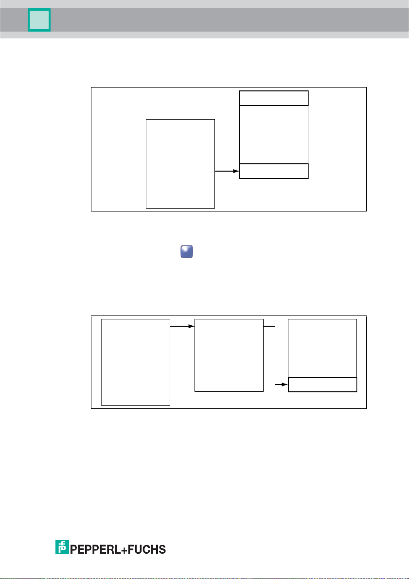
4.2 Displays and Controls
The device is equipped with the following displays and controls:
259778 2013-02
11
Page 12
IC-H H20-V1
1
2
3
Product Description
1 Status LED
2 LC display
3 Softkeys
4 Navigation keys
5 Trigger keys
6 Keypad
7 Interface
8 Battery compartment
9 M12 connection for read/write head
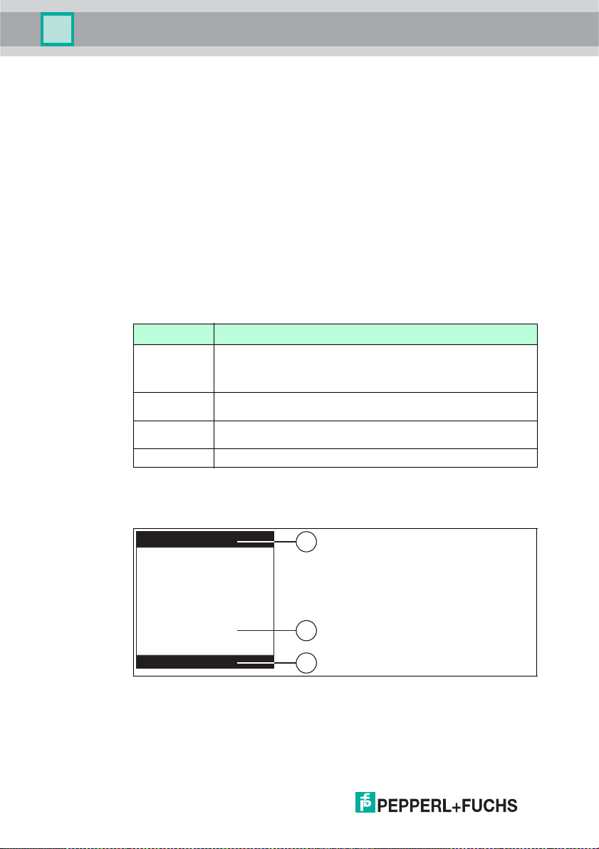
4.2.1 Status LED
The status LED indicates the following states:
Meaning of status LED
St at u s Descriptio n
Green ■ The handheld device is switched on.
Ye l lo w f la sh i n g The handheld device has executed a read or w rite command
Red flashing The handheld device has executed a read or w rite command
Off Read/write head is inactive
■ The interface has been changed.
■ Data has been read or written.
successfully.
unsuc cessfull y and in dicates an e rror.
4.2.2 Display
The display on the device consists of different areas:
1 Toolbar
2 Display
3 Softkey b ar
12
259778 2013-02
Page 13
IC-H H20-V1
Product Description
The following table lists all the symbols in the status bar and explains what they
mean:
Symbols in the status bar
Symbol Descr iption
Char ge state
Connection status
The battery capacity is between 50 % and 100 % .
The battery capacity is between 20 % and 50 % .
The battery capacity is between 0 % and 20 %. Charge the battery.
Battery is charging.
The handheld device is c onnected to an interface.
RS 232 is the preset interface.
PS/2 is the preset interface.
USB is the preset interface.
Bluetooth is the preset interface.
Data transfer
Data transfer in one direction: Data is sent from the handheld device to
the computer. A response from t he computer is not required.
Data transfer in two directions: Data is sent from the handheld device to
the computer. The handheld device then waits for a response from the
computer.
Keyboard mode: The handheld device is connected to the computer
via a USB or PS/2 interface.
Virtual COM port mode: The handheld device emulates an RS 232
interface via th e USB inter face to allow communication from the
computer to the handheld device as well. A response from the
computer is not required.
Secure mode
Memory status
0 % to 25 % of the internal memory is occupied.
25 % to 50 % of the internal memory is occupied.
50 % to 75 % of the internal memory is occupied.
75 % to 100 % of the internal memory is occupied.
259778 2013-02
13
Page 14
IC-H H20-V1
Product Description
Symb ol Descriptio n
Input mode
4.2.3 Button overview
The following table lists all the b uttons on the device and their names:
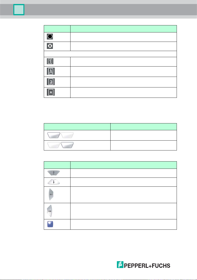
Selection buttons
Button Description
The internal memory is full. There internal memory has no more space
to store data.
Batch mo de inactive. Data is not cached in the internal memor y.
Nume rical input mode - data entered usin g the input keys appears in
the num erical form.
Alphabetical input mode - data entered using the inp ut keys appears in
alphabetical form.
Alphabetical input mode - data entered using the inp ut keys appears in
the form of lowercase letters.
Symbol input mode - data entered using the input keys appears in the
form of symbols.
Left selection button
Right se lection button
14
Navigation keys
Keys Des ignation
Up navigation key
Down na vig ation key
Left navigation key
Right navigation key
Enter navigation key
259778 2013-02
Page 15
IC-H H20-V1
Product Description
Function buttons
Button Description
Input keys
Keys "Numerical" m ode
Left function button
(= left trigger button)
Right function button
(= right trigger button)
"Alphanumerical
upper case" mode
Switc hes between "N umerical", "Alphanumerical upper case",
"Alphanumerical lower case" and "Symbols" mode.
1 Space, 1 Space, 1 Space
2 A, B, C, 2 a, b, c, 2 ! * = `
3 D, E , F, 3 d, e, f, 3 " + > {
4 G, H, I, 4 g, h, i, 4 # , ? |
"Alphanumerical
lower case"
mode
"Symbols "
mode
) < _
5 J, K, L, 5 j, k, l, 5 $ - @ }
6 M, N, O, 6 m, n , o, 6 % . [ ~
7 P, Q , R, S, 7 p, q, r, s, 7 & / \
8 T, U, V, 8 t, u, v, 8 ' : ]
9 W, X , Y, Z w, x, y, z ( ; ^
0 0 0 Scrolls
For data input fields : delete the last character. Otherwise: ESC function (exits
the menu without adopting the current settings.)
259778 2013-02
Spa ce
Spa ce
Spa ce
through the
different
symbol pages
15
Page 16
IC-H H20-V1
1
1
Product Description
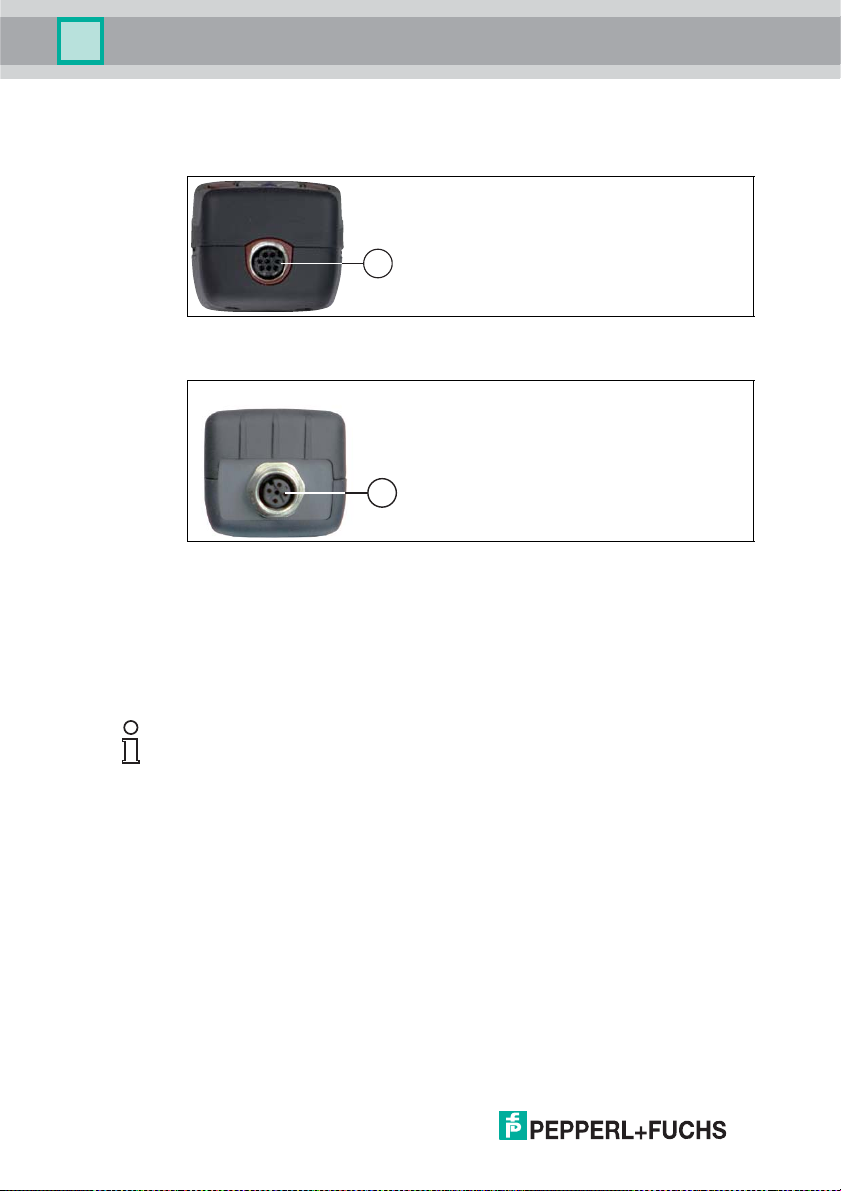
4.3 Connections
The handheld features the following connections:
1 8-pin connecting socket
1 4-pin M12 s ocket
4.4 Scope of Delivery
The following elements are included in the scope of delivery:
■ Handheld device without battery or battery compartment cover
■ CD with documentation (manual)
Note!
To com plete the devic e, s om e other compone nts are re quired in additi on to t he
handheld included in the scope of delivery. The basic equipment includes:
handheld, battery, double-ended cordset for handheld/read/write head, and
charger. All components can be obtained from Pepperl+Fuch s.
16
259778 2013-02
Page 17
IC-H H20-V1
Installation
5Installation
5.1 Preparation
Unpacking the unit
1. Check that all package contents are present and undamaged.
If anything is damaged, inform the shipper and contact the supplier.
2. Check that all items are present and correct based on your order and the
shipping documents.
If you have any questions, please contact Pepperl+Fuchs.
3. Keep the original packing material in case you need to store or ship the unit at
a later time.
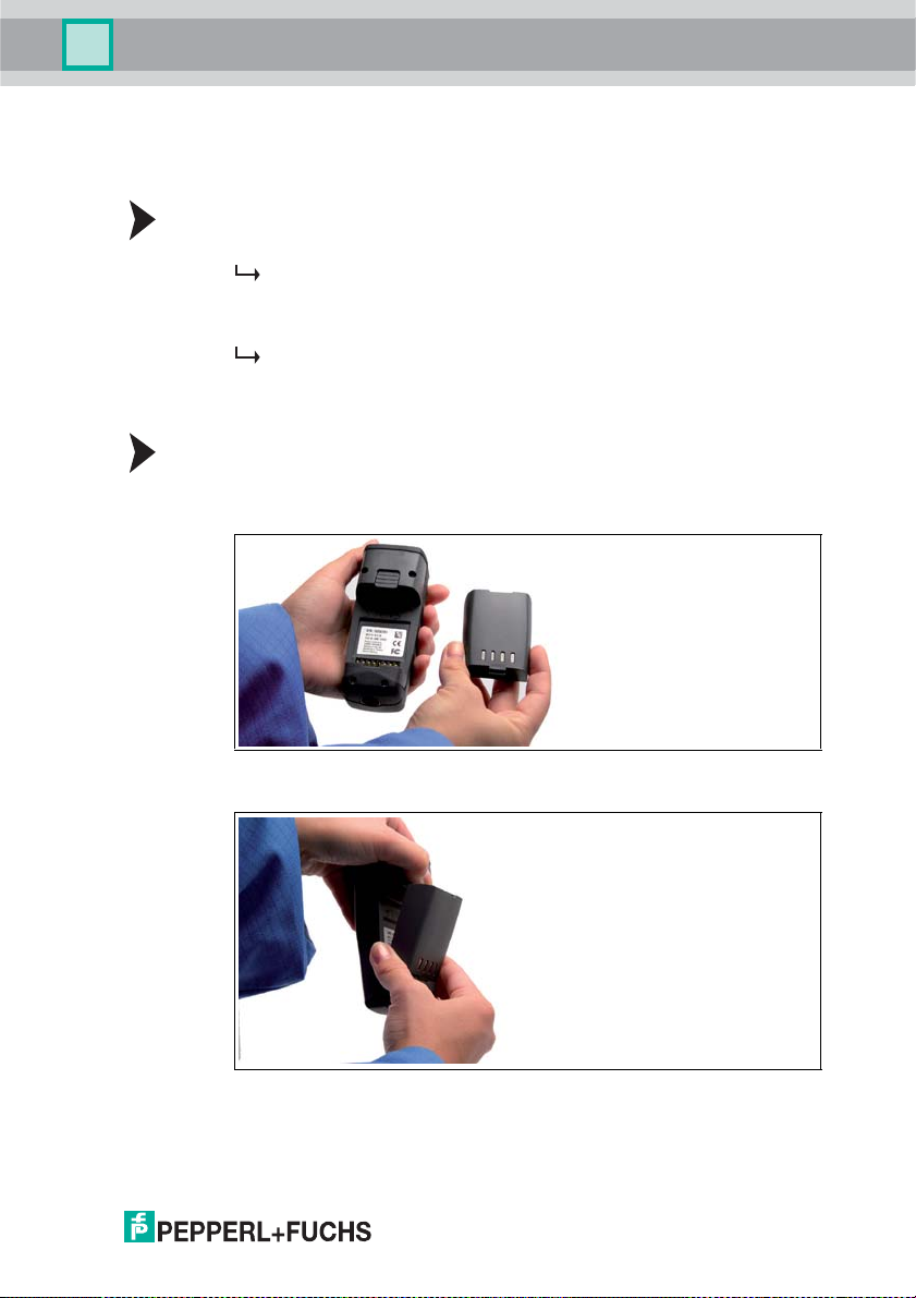
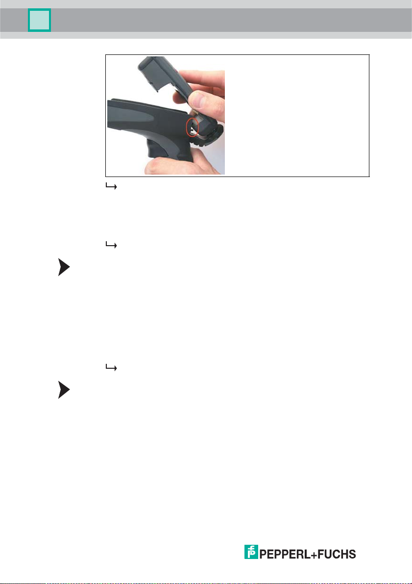
Fitting the battery
Fit the battery as follows:
1. Turn the battery so that you can remove it as s hown in the illustration.
2. Slide the p lastic tab on the battery into the corresponding recess on the
Handheld.
3. Push the locking device upwards and pu sh in the battery.
259778 2013-02
17
Page 18
IC-H H20-V1
Installation
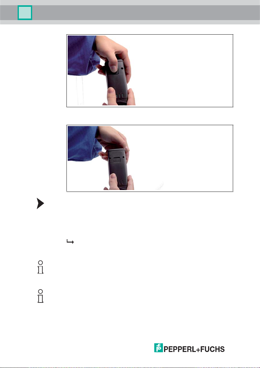
4. Push the battery in the Handheld, hold in position and release the locking
device so that the battery engages.
18
Chargin g the battery
Charge the battery as follows:
1. Connect the handheld device with battery to an interface cable.
2. Make sure the computer is switched on and then connect the interface cable
to computer.
When the handheld device is switched on, the symbols displayed in the
status bar on the handheld device indicate the charge state. See table
"Symbols in the status bar" on page 13
Note!
If you are operating the handheld via an RS 232 interface, connect the RS 232
interface power supply unit to the socket to charge the battery.
Note!
Completely discharged storage batteries
If the storage battery is completely discharged , you will have to wait at least 10
minutes before the Han dheld is ready for operation again.
259778 2013-02
Page 19
IC-H H20-V1
Installation
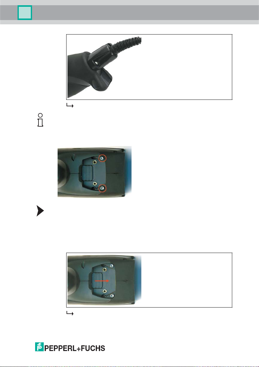
5.2 Handle attachment
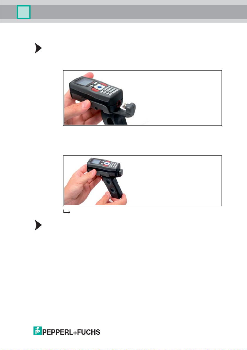
Attaching the standard handle
Proceed as foll ows to at tac h th e grip to th e hand held device :
1. Insert the handheld device with battery into the bracket on the handle.
2. Slide back the handheld device until the conne ctor on the ha ndle engages in
the cable connector socket on the handheld device.
3. P ush the handheld d evice firmly onto the con necto r unti l it is flush wi th t he
handle.
The handh eld device is attached to the handle.
Fitting a han dle with cable connection
Fit the handle to the Handheld as follows:
1. Remove the battery from the battery compartment of the Handhe ld if necessary.
2. Carefully pull the rear, flexible part of the handle attached to the plug
downwards.
3. Attach the cable connection socket on the Handheld to the plug on the
handle.
4. Slide the p lastic tab on the battery into the corresponding recess on the
Handheld.
259778 2013-02
19
Page 20
IC-H H20-V1
Installation
5. Push down the Handheld carefully until the locking device on the Handheld
6. Connect the interface cable to the cable connection socket underneath the
Fitting a handle with integrated storage battery
A handle with integrated battery is also available for this Handheld as an optional
accessory. Fit the handle to the Handheld as follows:
1. Remove the battery from the battery compartment of the Handhe ld if neces-
2. Slide the p lastic tab on the battery into the corresponding recess on the
3. Push down the Handheld carefully until the locking device on the Handheld
Securing the interfa ce cable to prevent inadvertent removal
Yo u have the op tion of attaching a cord grip to prevent the interface cable from
being pulled out inadvertently. Proceed as follows:
1. Sec ur e th e inte rf ace cable to th e ca ble connecti on socket on the handle.
2. Guide the cable through the slot on the cord grip and slide the cord grip
3. Make sure that you s lid e the co rd grip over the interface cable and in to the
4. Screw the cord grip to the handle using the screw s pr ovided.
The Handheld is now fi tted to the handle.
engage s in the handle.
handle.
The Handh eld is now ready for operation.
sary.
Handheld.
engage s in the handle.
The Handheld is now fi tted to the handle.
towards the cable connection socket.
correct position.
20
259778 2013-02
Page 21
IC-H H20-V1
Installation
Note!
We recommend mounting the handheld device using the screws provided for
extra security. There are two screw holes in the lower sec tion of the handle (see
illustration).
The interface cable is secured against inadvertent removal.
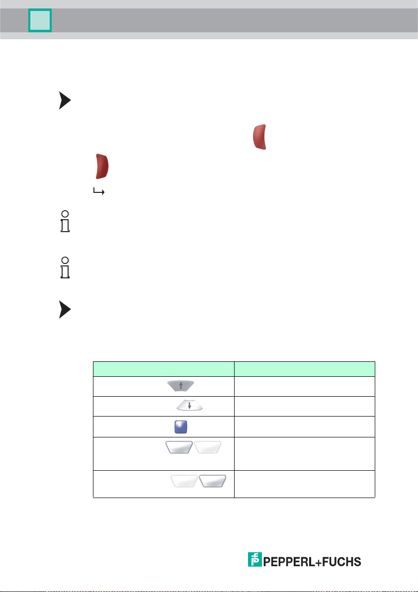
Removing the handle
Remove the handle as follows:
1. If you have secured the handheld with screws on the handle, remove the
screws.
2. Push the locking device in the direction of the arrow and press the handheld
ou t of the r etainer.
The handle is removed.
259778 2013-02
21
Page 22
IC-H H20-V1
Commission ing
6 Commissioning
6.1 Switching on/off
Switching on the handheld device
Switch on the ha ndheld device as follows:
Press and hold either the left function button ( ) or the right function button
( ) for approx.1 second.
The handheld device switches on.
Note!
The Handheld switches into standby automatically 2 minutes after the last
keystroke.
Note!
If you connect the device to the USB or PS/2 interface of your PC, the device
switches on automatically.
Switching off the Handheld
The Handheld switches off automatically if it remains idle for more than 2 hours.
6.2 Basic operation
6.2.1 Navigating through menus
Button Func tion
Up navigation button ( )
Down navigatio n button ( )
Enter navigation button ( )
Left selection button ( )
Right selection button ( )
22
Scroll up through different menus and
subm enus
Scroll down through different menus and
subm enus
Select menus, submenus and individual
menu entries
Function depends on the menu.
This button is usuall y used to confir m a
command (e.g., OK) or execute a
command (e.g., read).
Function depends on the menu.
This button is usuall y used to stop or
cancel a command (e.g., ESC).
259778 2013-02
Page 23
IC-H H20-V1
Commission ing
Activating/Deactivating a menu entry
Activate/deactivate a menu entry as follows:
1. Scroll to th e m enu e ntr y o f your choice using the up navigat io n button
( ) or the down navigation button ( ).
The menu entry currently selected is highlighted black.
2. P res s the E nte r navigat ion bu tton t o act ivate the menu entry ( ).
A star appears in front of the activated menu entry.
3. Press the Enter navigation button again to deactivate the menu entry ( ).
The star no l onger a ppe ars in fro nt of the deactivate d menu entry.
4. Press the left selection button to confirm your selection ( ).
6.2.2 Data input
Button Function
Input keys 0...9
( ... )
SHIFT input button
()
CLEAR i nput button
()
Enter numerical or alphanumerical values (depending on the
mode selected).
Switch between the different input modes.
(The selected mode is indicated in t he sym bol bar o f the
handheld device on the right.)
For data input fields: delete the character last entered.
Within menus: Exit the menu.
6.3 Connecting a Read/Write Head
Yo u can connect various read /write heads for IDENTControl to the handheld.
Connect the read/write heads to the 4-pin M12 socket on the front of the handheld
usi ng the V1 -G-0.5/2.5M -PUR -V1- G doubl e- ende d cord set.
The double-ended cordset can b e obtained from Pepperl+Fuchs.
Tip
Connect the read/write head before switching on the handheld. When switched
on, the handheld automatically detects the read/write head.
If you connect a new read/write head while the handheld is switched on, you must
Teach-in the new read/write head. See chapter 7.1.
259778 2013-02
23
Page 24

IC-H H20-V1
Commission ing
6.4 Operating modes
Caution!
Data loss
An i ncorrectly preset interface may lead to data l oss.
Make sure that the Handheld is connected to the interface (USB, RS 232,
Bluetooth) preset in the Ha ndheld. If necessary, use another interface cable or
modify the settings in the Handheld.
6.4.1 Wireless operation ( batch mode)
Wireless operation of the handheld device is recommended for certain
applications. As soon as you remove the interface cable (USB, RS 232 cable) or
move outside the range of a Bluetooth connection, the handheld device switches
automatically to "Batch mode": In this mode, the read data is stored in the internal
memory of the handheld device. You then have the option of transferring the data
stored in the handheld device to the computer at a later tim e.
Note!
Using batteries
Yo u will require a battery or a handle with integral battery to operate the handheld
device using a wireless connection or a cable via an RS 232 interface.
A battery is n ot normally required for cable operation via USB. However, this
depends on the current strength that the computer supplies via the USB
con necti on. If th e comp uter does no t supply suffi cient pow er to the USB por t, you
will require a USB hub with a separate power supply or will have to fit a battery to
the handheld device.
If you wish to operate the handheld device without a handle using a cable via the
USB port, you must fit a battery compartment cover ODZ-MAH-BLANK to the
device.
This optional accessory is available from Pepperl+Fuchs.
6.4.2 Cable operation: RS 232
Configuring the RS 232 interface on the handheld device
Configure the RS 232 command interface on the handheld device as follows:
1. Select Settings > Interface
2. Activate the RS 232 interface.
The RS 232 submenu opens.
3. Edit the relevant parameters.
4. Press the left selection button to confirm your entries ( ).
The interface is now active.
5. Press the right selection button to exit the menu ( ).
24
259778 2013-02
Page 25
IC-H H20-V1
Commission ing
Tip
Further information on interface settings see chapter 9.3.7
Connecting the interface cable to the Handheld
To connect the interface cable to the H andheld, proceed as follows:
1. Turn t he 8 -pi n D IN p lu g so t hat th e ar rows on th e plu g a re p oi nt ing d ow nwa rd s.
2. Hold the Handheld in your hand w ith the controls facing upwards.
3. Insert the plug into the corresponding ca ble connection socket on the
Handheld.
4. Press the plug firmly into the cable connection socket until the locking device
audibly engages.
The interface cable is now connected to the Handheld.
Connecting the Handhe ld to the computer via the RS 232 interface cable
Conne ct the Hand held to the comp uter as follows :
1. Switch off the computer.
2. Connect the RS 232 plug on the interface cable to the RS 232 interface on the
computer.
3. Connect the low-voltage plug on the power supply unit to the low-voltage
socket on the RS 232 interface cable.
4. Connect the power supply unit to the mains power supply.
5. Switch on the computer.
The Handheld switches on automatically once you have connected it to
the computer. The symbols and are displayed in the toolbar.
6.4.3 Cable operation: PS/2
Configuring the PS/ 2 interface on the handheld device
Configure the PS/2 command interface on the handheld device as follows:
1. Select Settings > Interface
2. Activate the PS2 interface.
You are prompted to select whether you wish to operate the handheld
device in PS2 mode.
3. Press the left selection button to confirm your selection ( ).
The interface is now active.
4. Press the right selection button to exit the menu ( ).
259778 2013-02
25
Page 26
IC-H H20-V1
Commission ing
Note!
Required PS/2 interface cable
Yo u will require a PS/2 interface cable with the following connectors to connect
the Handheld to the computer:
Connecting the interface cable to the Handheld
To connect the interface cable to the H andheld, proceed as follows:
1. Turn t he 8 -pi n D IN p lu g so t hat th e ar rows on th e plu g a re p oi nt ing d ow nwa rd s.
2. Hold the Handheld in your hand w ith the controls facing upwards.
3. Insert the plug into the corresponding ca ble connection socket on the
4. Press the plug firmly into the cable connection socket until the locking device
Note!
Connection cable with fitted grip
If y ou have mo unte d the Han dhel d to th e op tion al grip, con nect the inter face cab le
to the cab le co nnec tion soc ket on the g rip.
■ 8-pin DIN connector for connection to the Handheld.
■ PS/2 socket for connecting an external keyboard.
■ PS/2 connector for connection to the computer.
Handheld.
audibly engages.
The interface cable is now connected to the Handheld.
26
Connecting the handhe ld device to the computer usi ng a PS/2 interface
cable
Connect the handheld device to the computer as follows:
1. Switch off the computer.
2. If an external keyboard is connected to the computer, disconnect from the
computer.
3. If you are using a USB keyboard, connect the keyboard to the PS/2 socket on
the in terface cab le using a correspon ding adapter. If you are u sing a keyboard
with PS/2 plug, connect the p lug directly to the PS/2 socket on the interface
cable.
4. Connect the PS/2 plug on the interface cable to the keyboard port on the
computer.
5. Switch on the computer.
After you have connected the handheld device to the computer, it
switches on a utomatically. The symbols and appear in the status
bar.
Power is supplied to the hand held device via the PS/2 inter face. This is why you
do not require an additional power supply.
259778 2013-02
Page 27
IC-H H20-V1
Commission ing
6.4.4 Cable operation: USB
Configuring the US B interface on the handheld device
Configure the USB comman d interface on the handheld device as follows:
1. Select Settings > Interface
2. Activate the US B interface.
The USB submenu opens.
3. Press the Enter navigation button to activate the required mode ( ).
4. Press the left selection button to confirm your entries ( ).
The interface is now active.
5. Press the right selection button to exit the menu ( ).
Tip
Further information on interface settings see chapter 9.3.7
Connecting the interface cable to the Handheld
To connect the interface cable to the H andheld, proceed as follows:
1. Turn t he 8 -pi n D IN p lu g so t hat th e ar rows on th e plu g a re p oi nt ing d ow nwa rd s.
2. Hold the Handheld in your hand w ith the controls facing upwards.
3. Insert the plug into the corresponding ca ble connection socket on the
Handheld.
4. Press the plug firmly into the cable connection socket until the locking device
audibly engages.
The interface cable is now connected to the Handheld.
Note!
Connection cable with fitted grip
If y ou have mo unte d the Han dhel d to th e op tion al grip, con nect the inter face cab le
to the cab le co nnec tion soc ket on the g rip.
Connecting the Handheld to the computer via the USB interface cable
Conne ct the Hand held to the comp uter as follows :
Insert the USB plug on the interface cable into a free USB port on the computer. It
does not matter whether the computer is switched on or off.
The Handheld switches on automatically once you have connected it to the
computer. The symbols and are displayed in the toolbar.
259778 2013-02
27
Page 28
IC-H H20-V1
Commission ing
6.4.5 Operating with Bluetooth
This handheld device is equipped with a class 1 wireless Bluetooth interface
incorpo rating a radio system that enables wireless point-to-point communication
with other Bluetooth-compatible devices. If the other Bluetooth-compatible device
also has a class 1 radio system, a sensing range of ap prox. 100 m is achieved in a
free field. If the handheld device is connected to a class 2 or 3 Bluetoothcompatible device, the sensing range decrease s accordingly.
If the handheld device is located outside the sensing range, it stores the read data
in the internal me mo r y. The hand held device at tem p ts to se nd the read data un til
the connection with the B luetooth-compatible device is established again. As
soon as the handheld device sends data to the Bluetooth-compatible device, it is
deleted from the internal memory automatically.
Note!
Yo u will require a M AC address to connect the ha ndheld device to a Bluetoothcompatible device. The MAC address is usually printed on the Bluetooth device
next to the serial number or appears in the manual accompanying your Bluetooth
device.
Connecting the handheld device via Bluetooth
Connect the handheld device to a Bluetooth-compatible device (e.g., laptop with
corresponding Bluetooth USB dongle) as follows:
1. Select Settings > Interface.
2. Activate the Bluetooth interface.
The Bluetooth submenu opens.
3. Press the Enter navigation button to activate the required mode ( ).
4. Enter the M AC address in the file input field of the BD_MAC menu en try. The
address consists of 12 digits, e.g., 00 0A3A72C2D0.
28
5. Press the left selection button to confirm your entries ( ).
A connection is established between the two devices. The connection
may take a few moments to establish under certain circumstan ces. The
symbols and appear in the status bar.
Tip
Further information on interface settings see chapter 9.3.7
259778 2013-02
Page 29
IC-H H20-V1
0 (C) P+F
IDENT-I
IPH-18GM-V1
#121115
OK
Versi on
Read/Write
Storage
Settings
Te a ch i n
Applications
About
Data read
Data write
Data copy
Read fixcode
Format tag
Address: 0000
No. bocks: 01
Options
read ESC
Read/Write
Storage
Settings
Te a ch i n
Applications
About
Operation
7Operation
7.1 Teaching In
Once you have connected a read/wr ite he ad to the h andheld, th e type of data fo r
the read/write head mus t be taught in on the h andheld. To do so, select the
Te a ch - i n menu item in the main menu. To start the Teach-in process, press the
"Enter" navigation button ( ).
Once the Teach-in proc ess has c omp let ed s uccessfully, the data for the
connected read/write head appears on the display. If the Teach-in process fails,
an error messag e is displayed. See see chapter 8
7.2 Read Data
259778 2013-02
Before the handheld can read the d ata stored on a tag, you must configure the
correct Ta g t yp e . Overview of available settin gs .
The data that is read is saved on the handheld and/or sent to the PC, depending
on the setting configured under Settings > Send/save (see chapter 6.4).
If you w ant to add a time stamp to the data r ead, go to the Settin gs > Ti me
stamp menu and check the ON option.
Address
In th e data i nput field of the Address menu entry, you have the option of changing
the start address.
29
Page 30
IC-H H20-V1
Data read
Data write
Data copy
Read fixcode
Format tag
Address: 0000
No. bocks: 01
Data:
Options
write ESC
Read/Write
Storage
Settings
Te a ch i n
Applications
About
Operation
Start addresse s specify the location of the individual data blocks on data carriers.
You can read out specific data blocks and transfer data by changing the start
address.
Defining the start address
Define the start address as follows:
1. Select Addre ss .
2. Enter the start address using the input buttons.
3. Press the left selection button to confirm your entry ( ).
If the read op eration is su ccessful, t he status LED in it ia lly flashes yel low befo re
lighting up green. If you selected the buzzer and the vibration alarm in the
"Settings" menu, you will hear an audible signal and the handheld will vibrate. The
read-in data will then be displayed in the selected data format. If the transmission
fails, the status LED flashes briefly red and an er ror message is output. See see
chapter 8
Tip
Additional options see chapter 9.1.1
Note!
All data is displayed in the format chosen in the "Data format" submenu (ASCII,
HEX, DEC).
7.3 Write Data
30
The table below shows you how to input data into the handheld.
Data formats
Data
fo rma t
ASCI I In ASCII format,
Notes
numbers 0 to 9, letters
A to Z and special
characters stored in
the Handheld are
available.
Block quantity
(maximum 32)
01 xxxx HAND
02 xxxx
03 ...
Form at Example
xxxx
HAND
HELD
259778 2013-02
Page 31

IC-H H20-V1
Operation
Data
fo rma t
HEX
(hexadecimal)
DEC
(decimal)
Notes
In hexadecimal data
format, numb ers 0 to 9
and letters A to F are
available.
In de cimal data format,
numbers 0 to 255 are
available.
Block quantity
(maximum 32)
01 xx xx xx xx
02 xx xx xx xx
03 ...
01 xxx x xx xxx xx x
02 xxx x xx xxx xx x
03 ...
Form at Example
(spaces are not
required)
xx xx xx xx
(spaces are not
required)
xxx x xx xxx xx x
11 22 11 22
11 22 11 22
1A 2B 3C 4D
111 222 111
222
111 222 111
222
010 020 030
040
Setting the data format
1. Select Read /Wri te > Write data > Op tions > Da ta format.
2. Press the Enter navigation button to select the required data format ( ).
3. Press the left selection button to confirm your selection ( )
4. Press the right selection button to exit the op tions ( ).
Transferring data to data carriers
To transfer data to data carriers, proceed as follows:
1. Select Read /Wri te > Write data > Data.
One or more data input fields are displayed (the number of data input
fields displayed is based on the number of blocks.)
2. Navigate to the individual data input fields using the up navigation button
( ) and the down navigation button ( ).
3. Enter the required data with the correct syntax for the selected data format
using the input bu ttons.
4. P res s the C LE AR input b utt on to delete in dividua l characters ( ). In
principl e, you can only delete the ch aracter last ente red , not individual
characters within the string.
5. Press the left selection button to confirm your entry ( ).
If th e form at o f the e ntered c haracters differs fr om th e specifie d d ata
format, a fault message is issued and the value is not adopted.
6. Position the read/write he ad on the handheld device directly in front of the
data carrier.
259778 2013-02
31
Page 32

IC-H H20-V1
Send
Edit
Delete
Send all
Delete all
Enter Data
Option ESC
Read/Write
Storage
Settings
Te a ch i n
Applications
About
Operation
7. Press the left selection button to write the data to the data carrier
().
If the write ope ration is successful, OK appears on the display and the
status LED flashes green. If you selected the buzzer and the vibration alarm in
the Settings menu, you will also hear an acoustic signal and the handheld will
vibra te. If the transmissi on fails, the st atus LED flash es briefl y r ed and a fault
messa ge is output.
Note!
Observe the input format
Data bytes in hexadecimal data format must always contain 2 characters and data
bytes in decimal data format must contain 3 characters.
7.4 Editing or Entering Data Man ually
32
Editing data manually
To edit data that has already been read in, proceed as follows:
1. Select Memory.
2. Scroll to the required data set using the left navigati on b utton ( ) or the right
navigation button ( ).
3. Press the left selection button ( ) to access the options.
4. Select Modify.
5. Press the bu tton to delete individual characters. In principle, you can
on ly delete th e charac ter last entered , n ot ind ividual characters wi thin the
string .
6. Enter the required changes using the input buttons.
7. Press the left selection button to confirm your changes ( ).
The value in the memory is modified.
259778 2013-02
Page 33

IC-H H20-V1
Send
Edit
Delete
Send all
Delete all
Enter Data
Option ESC
Read/Write
Storage
Settings
Te a ch i n
Applications
About
Operation
Note!
Observe the input format
Data bytes in hexadecimal data format must always contain 2 characters and data
bytes in decimal data format must contain 3 characters.
Entering data manually
Enter a new value as follows:
1. Select Memory .
2. Press the left selection button ( ) to access the options.
3. Select Enter data .
4. Enter the data set using the input buttons.
5. Press the Enter navigation button to confirm your entry ( ) .
259778 2013-02
The value is stored as a new data set.
Note!
Observe the input format
Data bytes in hexadecimal data format must always contain 2 characters and data
bytes in decimal data format must contain 3 characters.
33
Page 34

IC-H H20-V1
Troubleshooting
8 Troubleshooting
8.1 Error Message "Unknown System"
Possible C ause Error Repair
Unknow n system Connect and Teach-in the read/write head for the
8.2 "No transponder" fault message
IDENTControl system.
Possible c ause Solution
No transponder in the detection
ran ge
Incorrect transponder type setting Select the correct transponder type.
8.3 "No connection!" fault message
34
Position the handheld device correctly or move
transponder into the detection range.
259778 2013-02
Page 35

IC-H H20-V1
Troubleshooting
Possible c ause Solution
Incorrect interface setting Select the correct in terface and configure corr ectly.
No interface available Connect the correct interface cable.
8.4 "No saved data" fault message
Possible c ause Solution
All data sent and "Autom. del."
mode selec ted.
No data in memory Rea d or en ter d a ta m a nua lly.
-
8.5 "No data to copy" fault message
Possible c ause Solution
No data was read in beforehand. In the "Co py data" me nu, you can o nly copy data that
259778 2013-02
you have ju st read in. D ata in the me mory c annot be
copied.
Read in data in the "Copy data" menu and copy this
data directly from the menu.
35
Page 36

IC-H H20-V1
Software description PF_Ident
9 Software description PF_Ident
9.1 Menu Read/Write
The Read/Write menu offers the following opti ons:
■ Read in data from a data carrier. (Read data)
■ Write d ata to a data car rier. (Write data)
■ Read the data from a data carrier and write to other data carriers.
(Copy data)
■ Read the read only code from a data carrier. (Read fixcode)
■ Overwrite the data from a data carrier. (Form at data carr.)
■ Write a new command file or modify/delete an existing command file.
(Command files)
Note!
Save power
The read/write head consumes more power when switche d on.
The read/write head on the handheld device switches on when you execute a
command in the Read/Write menu. The green LED indicates that the head is
switched on. The read/wr ite head only switches off again when you exit the
releva nt submenu.
36
259778 2013-02
Page 37

IC-H H20-V1
Software description PF_Ident
9.1.1 Read/Write > Read data
In this menu, you have the option of reading data stored on a data or code carrier.
Read data menu
Sub menu Options
Menu entry Add ress
Description of menu entries
Address
In th e data i nput field of the Address menu entry, you have the option of changing
the start address.
Start addresse s specify the location of the individual data blocks on data carriers.
You can read out specific data blocks and transfer data by changing the start
address.
Defining the start address
Define the start address as follows:
1. Select Addre ss .
2. Enter the start address using the input buttons.
Number of blocks
3. Press the left selection button to confirm your entry ( ).
Number of blocks
In the data input field of the No. blocks menu entry, you have the option of
changing the number of blocks.
The num ber of blocks determines how many data bloc ks the Hand held reads from
the data carrier a nd how m any data blocks are written t o t he data c arr ie r. Each
address block contains 4 bytes, i.e. in ASCII format, you can enter 4 characters for
each block in the data input field of the Data menu entry, in hexadecimal data
format 8 characters (2 characters each) and in decimal data format 12 characters
(3 characters each).
259778 2013-02
37
Page 38

IC-H H20-V1
Software description PF_Ident
Changing the number of blocks
Change the number of blocks as follows:
1. Select Number of blocks.
2. P res s the C LE AR input b utt on to delete th e current e ntr y ( ).
3. Enter the n umber of blocks using the input bu ttons.
Options submenu
38
Sub menu Data format
Menu entry Copy
Assign button
Description of menu entries
Copy
You can use the Copy menu entry to transfer the data currently being read to the
Data write menu.
Copy data
Use this option to copy data a s fo llows:
1. R ead t he data from a data carrier.
2. P res s the righ t sele ction bu tton a fter th e l ast read data carri er to exit read
mode ( ).
3. Select Options > Copy.
If the copy operation is successful, "Data transferred" appears on the
display and the status LED lights up green. If the copy operation fails, a fault
messa ge is output. See see chapter 8
259778 2013-02
Page 39

IC-H H20-V1
Software description PF_Ident
Data format submenu
Sub menu --
Menu entry ASC II
Description of the submenu
Data format
In the Data format submenu, you can define the data format in which the data is
read or written.
Description of menu entries
Data formats
HEX
DEC
Data format Notes Form at
ASCI I In ASCII format, numbers 0 to 9,
HEX In hexadec imal data format,
DEC In decimal data format, numbers 0
letters A to Z and spec ial
characters stored in the Handheld
are available.
numbers 0 to 9 and letters A to F
are available.
to 255 are available.
xxxx (per block)
xx xx xx xx
(spaces are not required)
(per block)
xxx x xx xxx xx x
(spaces are not required)
(per block)
Note!
Chan gin g the da ta format
Changes to the data format in this menu modify the basic settings
Settings > D ata form at of the handheld device. Read and written data adopts
the data format selected in this menu.
259778 2013-02
39
Page 40

IC-H H20-V1
Software description PF_Ident
Assign button submenu
Sub menu --
Menu entry Left
Description of the submenu
Assign button
In the Assign button submenu, you can a ssign the command from the higher
level menu to the function buttons on the handheld device and the buttons on the
handle.
Caution! T he function buttons remain disabled until you exit the Assign button
subme nu.
Description of menu entries
Right
Handle
40
Button Description
Left The command from the higher level menu is assigned to the left function
button ( ).
Right The command from the highe r level m enu is assigned to the right
function butt on ( ).
Hand le The command from the higher level menu is assigned to the function
button on the hand le.
Information on the Read data fun ction
Read data
When the Read option is selected in the selection button function bar, the
handheld device executes the Read data function via the read/write head. The
data stored on a d ata carrier or code carrier is read and either transferred to the
handheld device memory or sent directly to a computer, depending on the setting.
Detailed instructions, see chapter 7.2.
259778 2013-02
Page 41

IC-H H20-V1
Software description PF_Ident
9.1.2 Read/Write > Write data
In this menu, you have th e opti on of w riting d ata to a d ata carrier.
Write d ata m enu
Sub menu Options
Menu entry Add ress
Description of menu entries
Address
In th e data i nput field of the Address menu entry, you have the option of changing
the start address.
Start addresse s specify the location of the individual data blocks on data carriers.
You can read out specific data blocks and transfer data by changing the start
address.
Defining the start address
Define the start address as follows:
1. Select Addre ss .
2. Enter the start address using the input buttons.
Number of blocks
Data
3. Press the left selection button to confirm your entry ( ).
Number of blocks
In the data input field of the No. blocks menu entry, you have the option of
changing the number of blocks.
The num ber of blocks determines how many data bloc ks the Hand held reads from
the data carrier a nd how m any data blocks are written t o t he data c arr ie r. Each
address block contains 4 bytes, i.e. in ASCII format, you can enter 4 characters for
each block in the data input field of the Data menu entry, in hexadecimal data
format 8 characters (2 characters each) and in decimal data format 12 characters
(3 characters each).
259778 2013-02
41
Page 42

IC-H H20-V1
Software description PF_Ident
Changing the number of blocks
Change the number of blocks as follows:
1. Select Number of blocks.
2. P res s the C LE AR input b utt on to delete th e current e ntr y ( ).
3. Enter the n umber of blocks using the input bu ttons.
Data
In the data inp ut field of the Data menu entry, you have the op tion of entering data
that you wish to wri te t o the data carr ie r.
Options submenu
42
Sub menu Data format
Menu entry --
Assign button
Data format submenu
Sub menu --
Menu entry ASC II
HEX
DEC
259778 2013-02
Page 43

IC-H H20-V1
Software description PF_Ident
Description of the submenu
Data format
In the Data format submenu, you can define the data format in which the data is
read or written.
Description of menu entries
Data formats
Data format Notes Form at
ASCI I In ASCII format, numbers 0 to 9,
HEX In hexadec imal data format,
DEC In decimal data format, numbers 0
Note!
Chan gin g the da ta format
Changes to the data format in this menu modify the basic settings
Settings > D ata form at of the handheld device. Read and written data adopts
the data format selected in this menu.
letters A to Z and spec ial
characters stored in the Handheld
are available.
numbers 0 to 9 and letters A to F
are available.
to 255 are available.
xxxx (per block)
xx xx xx xx
(spaces are not required)
(per block)
xxx x xx xxx xx x
(spaces are not required)
(per block)
Assign button submenu
Sub menu --
Menu entry Left
259778 2013-02
Right
Handle
43
Page 44

IC-H H20-V1
Software description PF_Ident
Description of the submenu
Assign button
In the Assign button submenu, you can a ssign the command from the higher
level menu to the function buttons on the handheld device and the buttons on the
handle.
Caution! T he function buttons remain disabled until you exit the Assign button
subme nu.
Description of menu entries
Button Description
Left The command from the higher level menu is assigned to the left function
button ( ).
Right The command from the highe r level m enu is assigned to the right
function butt on ( ).
44
Hand le The command from the higher level menu is assigned to the function
button on the hand le.
Information on the Write data function
Writing data
When the Write option is selected in the selection button function bar, the left
selection button ( ) is assigned the function Write data via the
read/write head. You can use the left selection butt on to w rite data to a data carrier
that you e ntered in the h andh eld devic e b eforehand.
Detailed instructions, see chapter 7.3.
259778 2013-02
Page 45

IC-H H20-V1
Software description PF_Ident
9.1.3 Read/Write > Copy data
In this m enu, you have the opt ion of copying a data set you have just read in to one
or more different data carriers.
Copy data menu
Sub menu Options
Menu entry Add ress
Description of menu entries
Address
In th e data i nput field of the Address menu entry, you have the option of changing
the start address.
Start addresse s specify the location of the individual data blocks on data carriers.
You can read out specific data blocks and transfer data by changing the start
address.
Defining the start address
Define the start address as follows:
1. Select Addre ss .
2. Enter the start address using the input buttons.
Number of blocks
3. Press the left selection button to confirm your entry ( ).
Number of blocks
In the data input field of the No. blocks menu entry, you have the option of
changing the number of blocks.
The num ber of blocks determines how many data bloc ks the Hand held reads from
the data carrier a nd how m any data blocks are written t o t he data c arr ie r. Each
address block contains 4 bytes, i.e. in ASCII format, you can enter 4 characters for
each block in the data input field of the Data menu entry, in hexadecimal data
format 8 characters (2 characters each) and in decimal data format 12 characters
(3 characters each).
259778 2013-02
45
Page 46

IC-H H20-V1
Software description PF_Ident
Changing the number of blocks
Change the number of blocks as follows:
1. Select Number of blocks.
2. P res s the C LE AR input b utt on to delete th e current e ntr y ( ).
3. Enter the n umber of blocks using the input bu ttons.
Options submenu
Sub menu Data format
Menu entry Copy
Description of menu entries
Copy
You can use the Copy menu entry to transfer the data currently being read to the
Data write menu.
Copy data
Use this option to copy data a s fo llows:
1. R ead t he data from a data carrier.
2. P res s the righ t sele ction bu tton a fter th e l ast read data carri er to exit read
mode ( ).
3. Select Options > Copy.
If the copy operation is successful, "Data transferred" appears on the
display and the status LED lights up green. If the copy operation fails, a fault
messa ge is output. See see chapter 8
46
259778 2013-02
Page 47

IC-H H20-V1
Software description PF_Ident
Data format submenu
Sub menu --
Menu entry ASC II
Description of the submenu
Data format
In the Data format submenu, you can define the data format in which the data is
read or written.
Description of menu entries
Data formats
HEX
DEC
Data format Notes Form at
ASCI I In ASCII format, numbers 0 to 9,
HEX In hexadec imal data format,
DEC In decimal data format, numbers 0
letters A to Z and spec ial
characters stored in the Handheld
are available.
numbers 0 to 9 and letters A to F
are available.
to 255 are available.
xxxx (per block)
xx xx xx xx
(spaces are not required)
(per block)
xxx x xx xxx xx x
(spaces are not required)
(per block)
Note!
Chan gin g the da ta format
Changes to the data format in this menu modify the basic settings
Settings > D ata form at of the handheld device. Read and written data adopts
the data format selected in this menu.
259778 2013-02
47
Page 48

IC-H H20-V1
Software description PF_Ident
Inform ation on the Copy data function
Copying data
To copy a data set from one data carrier to anothe r data carrier, proceed as
follows:
1. Select Read /Wri te > Copy data .
2. Position the read/write he ad on the handheld device directly in front of the
data carrier that you wish to copy the data set from.
3. Press the left selection button ( ).
The data set appea rs on the display.
4. Then po sition the read/write head on the handheld device directly in front of
the data carrier to w hich you wi sh to c opy the data set.
5. Press the right selection button ( ).
"OK" appears on the display.
6. P res s the C LE AR input b utt on to exit t he function ( ).
9.1.4 Read/Write > Read fixcode
In this menu, you have the option of reading the read on ly code o n a data carrier.
Read fixco de menu
48
Sub menu Options
Menu entry --
259778 2013-02
Page 49

IC-H H20-V1
Software description PF_Ident
Options submenu
Sub menu Data format
Menu entry --
Assign button
Data format submenu
Sub menu --
Menu entry ASC II
HEX
DEC
Description of the submenu
Data format
In the Data format submenu, you can define the data format in which the data is
read or written.
259778 2013-02
49
Page 50

IC-H H20-V1
Software description PF_Ident
Description of menu entries
Data formats
Data format Notes Form at
ASCI I In ASCII format, numbers 0 to 9,
HEX In hexadec imal data format,
DEC In decimal data format, numbers 0
Note!
Chan gin g the da ta format
Changes to the data format in this menu modify the basic settings
Settings > D ata form at of the handheld device. Read and written data adopts
the data format selected in this menu.
Assign button submenu
letters A to Z and spec ial
characters stored in the Handheld
are available.
numbers 0 to 9 and letters A to F
are available.
to 255 are available.
xxxx (per block)
xx xx xx xx
(spaces are not required)
(per block)
xxx x xx xxx xx x
(spaces are not required)
(per block)
50
Sub menu --
Menu entry Left
Right
Handle
Description of the submenu
Assign button
In the Assign button submenu, you can a ssign the command from the higher
level menu to the function buttons on the handheld device and the buttons on the
handle.
Caution! T he function buttons remain disabled until you exit the Assign button
subme nu.
259778 2013-02
Page 51

IC-H H20-V1
Software description PF_Ident
Description of menu entries
Button Description
Left The command from the higher level menu is assigned to the left function
button ( ).
Right The command from the highe r level m enu is assigned to the right
function butt on ( ).
Hand le The command from the higher level menu is assigned to the function
button on the hand le.
Information on the Re ad fixcode fu nction
Reading a read only code
To read the r ead only code from a data carrier, proceed as follows:
1. Select Read /Wri te > Read f ixcode.
2. Position the read/write he ad on the handheld device directly in front of the
data carrier.
3. Press the left selection button ( ).
If the read operation is successful, the status LED will initially flash yellow
before switching to a steady green. If you selected the buzzer and the
vibration alarm in the Settings menu, you will also hear an acoustic signal and
the handheld will vibrate. The read-in data will then be displayed in the
selected format. If the transmission fails, the status LED flashes briefly red
and a fault message is output. See see chapter 8
4. Press the right selection button to exit the function ( ).
259778 2013-02
51
Page 52

IC-H H20-V1
Software description PF_Ident
9.1.5 Read/Write > Format data car.
In this menu, you have th e opti on of f orm atting or d eleti ng the compl ete data
carrier by overwriting it with a self-defined character string.
Form at data carr. me nu
Sub menu Options
Menu entry Data
Description of menu entries
Data
In the Data field, you can enter the byte (length = 1 byte) that you wish to write to
the data carrier.
Options submenu
52
Sub menu Data format
Menu entry --
Assign button
259778 2013-02
Page 53

IC-H H20-V1
Software description PF_Ident
Data format submenu
Sub menu --
Menu entry ASC II
Description of the submenu
Data format
In the Data format submenu, you can define the data format in which the data is
read or written.
Description of menu entries
Data formats for the "Overwrite data carrier" function
HEX
DEC
Data format Notes Form at
ASCI I Numb ers 0 to 9, l etters A to Z and
HEX Numbers 0 to 9 and letters A to F
DEC Numbers 0 to 255 are available in
special characters stored in the
handheld device are available in
ASCII format.
are available in hexadecimal data
format.
decimal data format.
x
ASCII characters that cannot be
displayed: /DEC (e.g., "/013" for
CR)
xx
(Spaces are not essential)
xxx
(Spaces are not essential)
Note!
Chan gin g the da ta format
Changes to the data format in this menu modify the basic settings
Settings > D ata form at of the handheld device. Read and written data adopts
the data format selected in this menu.
259778 2013-02
53
Page 54

IC-H H20-V1
Software description PF_Ident
Assign button submenu
Sub menu --
Menu entry Left
Description of the submenu
Assign button
In the Assign button submenu, you can a ssign the command from the higher
level menu to the function buttons on the handheld device and the buttons on the
handle.
Caution! T he function buttons remain disabled until you exit the Assign button
subme nu.
Description of menu entries
Right
Handle
54
Button Description
Left The command from the higher level menu is assigned to the left function
button ( ).
Right The command from the highe r level m enu is assigned to the right
function butt on ( ).
Hand le The command from the higher level menu is assigned to the function
button on the hand le.
Information on the Overwrite data carrier function
Overwriting data carriers
1. Select Read /Wri te > Overw rite d ata carri er > Data.
2. P res s the C LE AR input b utt on to delete in dividua l characters ( ). In
principl e, you can only delete the ch aracter last ente red , not individual
characters within the string.
259778 2013-02
Page 55

IC-H H20-V1
Software description PF_Ident
3. Enter the value with which you wish to overwrite the data carrier using the
input button s. Make su re th e co rrect data format is se lec te d.
4. Press the left selection button to confirm the entry ( ).
If th e form at o f the e ntered c haracters differs fr om th e specifie d d ata
format, a fault message is issued. The value is not adopted.
5. Position the read/write he ad on the handheld device directly in front of the
data carrier.
6. Press the left selection button ( ).
If the read operation is successful, "OK" ap pears on the display and the status
LED flashes green. If you selected the buzzer and the vibration alarm in the
Settings menu, you will also hear an acoustic signal and the hand held will vibrate.
The re ad- in data will the n be displayed in the selec ted form at. If the transmission
fails, the status LED flashes briefly red and a fault message is output. See see
chapter 8
9.1.6 IP* Read/Write Heads
Operating frequency: 125 kHz.
Read/Write > Wr ite fixcode
In this menu, you have the option o f writing a fix code to the wr itable area of data
carrier types 11 and 14.
Write fixcode menu
Sub menu Options
Menu entry Fix type
Data
Description of menu entries
Fix type
In the data input field of the Fix type menu entry, you have the option of
determining whether the fix code written to the data carrier can be modified or
overwritten.
Permanent fix code "02"
259778 2013-02
Rewritable fix co de Data carrier type, e.g. "11" for IPC11
55
Page 56

IC-H H20-V1
Software description PF_Ident
Data
In the Data field, you have the option of entering data that you wish to write to the
data carrier.
Options submenu
Sub menu Data format
Menu entry --
Assign button
Data format submenu
Sub menu --
Menu entry ASC II
HEX
DEC
Description of the submenu
Data format
In the Data format submenu, you can define the data format in which the data is
read or written.
56
259778 2013-02
Page 57

IC-H H20-V1
Software description PF_Ident
Description of menu entries
Data formats for the fixco de
Data format Notes Form at
ASCI I In ASCII format, numbers 0 to 9,
HEX In hexadec imal data format,
DEC In decimal data format, numbers 0
Note!
Chan gin g the da ta format
Changes to the data format in this menu modify the basic settings
Settings > D ata form at of the handheld device. Read and written data adopts
the data format selected in this menu.
Assign button submenu
letters A to Z and spec ial
characters stored in the handheld
are available.
numbers 0 to 9 and letters A to F
are available.
to 255 are available.
xxxxx
xx xx xx xx x x
(spaces are not required)
xxx x xx xxx xx x xxx
(spaces are not required)
Sub menu --
Menu entry Left
Right
Handle
Description of the submenu
Assign button
In the Assign button submenu, you can a ssign the command from the higher
level menu to the function buttons on the handheld device and the buttons on the
handle.
Caution! T he function buttons remain disabled until you exit the Assign button
subme nu.
259778 2013-02
57
Page 58

IC-H H20-V1
Software description PF_Ident
Description of menu entries
Button Description
Left The command from the higher level menu is assigned to the left function
button ( ).
Right The command from the highe r level m enu is assigned to the right
function butt on ( ).
Hand le The command from the higher level menu is assigned to the function
button on the hand le.
Instructions on Write fixcode function
Write fixcode
Write a fixcode to a data carrier as follows:
1. Select Read/Write > Write fixcode > Fix type.
2. Press the CLEAR input key ( ) to delete the default value.
3. Depending on whether you wish to set a variable or rewritable fixcode, enter
the relevant value using the input keys. See see "Fix type" on pag e 55
4. Press the left softkey ( ) to confirm your entry.
5. Select Data.
6. E nt er t he relevant data in the co rrec t syntax for the data form at selected usi ng
the input keys. The length of th e fixcode is 5 by tes.
7. Press the left softkey ( ) to confirm the entry.
If the character entered does not correspond with the syntax of the data
format, a fault indication is issued and the value is not accepted.
8. Po sition th e read/w rite he ad o n the Handhel d directly b eside th e data carri er.
9. Press the left softkey ( ) to confirm the entry.
If the write process is successful, "OK" appears on the display and the status LED
flashes green. If you have activated the buzzer and the vibration alarm in the
Settings menu, an acoustic signal sounds and the Handheld vibrates. If the
transfer was unsuccessful, the status LED briefly flashes red and a fault indication
is issued. S e e see chapte r 8
58
Note!
Observe the input format
Data bytes in hexadecimal data format must always contain 2 characters and data
bytes in decimal data format must contain 3 characters.
259778 2013-02
Page 59

IC-H H20-V1
Software description PF_Ident
Read/Writ e > Read Register
In the Read register menu, you have the option of reading specific configuration
areas on the read/write tag.
For further information on configuring IPC03 read/write tags, see chapter 10.5.
Read register menu
Sub menu Protection
Menu entry --
Control
Protection submenu
Sub menu Options
Menu entry Read protect (start/end)
Write protect (start/end)
Description of Menu Entries
Read Protection
The start an d end ad dr ess configure d fo r t he read- prote cte d d ata po in t is
displayed in the Read protection menu entry.
Write p rotect
In the Write protection menu e ntry, you can view the start and end address for
the write-protected data area.
259778 2013-02
59
Page 60

IC-H H20-V1
Software description PF_Ident
Note!
The data points can be read out or written only when passwo rd mode is activated
and the correct password is s ent.
Options submenu
Sub menu apply to key
Menu entry --
Assign button submenu
60
Sub menu --
Menu entry Left
Right
Handle
Description of the Submenu
Assign button
In the Assign button submenu, you can a ssign the command from the higher
level menu to the function buttons on the handheld device and the buttons on the
handle.
Caution! T he function buttons remain disabled until you exit the Assign button
subme nu.
259778 2013-02
Page 61

IC-H H20-V1
Software description PF_Ident
Description of Menu Entries
Button Description
Left The command from the higher level menu is assigned to the left function
button ( ).
Right The command from the highe r level m enu is assigned to the right
function butt on ( ).
Hand le The command from the higher level menu is assigned to the function
button on the hand le.
Control submenu
Sub menu Options
Menu entry Standard read (start/end)
PSW protect
User bits
Description of Menu Entries
Standard read
In the Standard read menu entry, you can view the start and end address settings
for the reading ar ea.
Passwo rd pr otect
In the data input field of the Password protect menu entry, you can see whether
password mode ha s be en activated or deactivate d.
User bits
In the data input field of the User bits menu entry, you can view the entered user
infor matio n.
259778 2013-02
61
Page 62

IC-H H20-V1
Software description PF_Ident
Options submenu
Sub menu apply to key
Menu entry --
Assign button submenu
62
Sub menu --
Menu entry Left
Right
Handle
Description of the Submenu
Assign button
In the Assign button submenu, you can a ssign the command from the higher
level menu to the function buttons on the handheld device and the buttons on the
handle.
Caution! T he function buttons remain disabled until you exit the Assign button
subme nu.
259778 2013-02
Page 63

IC-H H20-V1
Software description PF_Ident
Description of Menu Entries
Button Description
Left The command from the higher level menu is assigned to the left function
button ( ).
Right The command from the highe r level m enu is assigned to the right
function butt on ( ).
Hand le The command from the higher level menu is assigned to the function
button on the hand le.
Read/Write > Wr ite Register
In the Write register menu, you have the option of writing specific configuration
areas on the read/write tag.
For further information on configuring IPC03 read/write tags, see see chapter
10.5.
Write r egister menu
Sub menu Protection
Menu entry Password
Control
Description of the Submenu
Passwo rd
In the data input fields of the Password menu entry, you have the option of
changing an existing password.
259778 2013-02
63
Page 64

IC-H H20-V1
Software description PF_Ident
Protection submenu
Sub menu Options
Menu entry Read protect (start/end)
Description of Menu Entries
Read protect
In the Read protect menu entry, you have the option of setting the start and end
areas (in bits) for read protection in the file entry fields.
Write p rotect
In the data input fields in the Write protect menu entry, you have the option of
defining the start and end address of the write-protected data area.
Options submenu
Write protect (start/end)
64
Sub menu apply to key
Menu entry --
259778 2013-02
Page 65

IC-H H20-V1
Software description PF_Ident
Assign button submenu
Sub menu --
Menu entry Left
Description of the Submenu
Assign button
In the Assign button submenu, you can a ssign the command from the higher
level menu to the function buttons on the handheld device and the buttons on the
handle.
Caution! T he function buttons remain disabled until you exit the Assign button
subme nu.
Description of Menu Entries
Right
Handle
Button Description
Left The command from the higher level menu is assigned to the left function
button ( ).
Right The command from the highe r level m enu is assigned to the right
function butt on ( ).
Hand le The command from the higher level menu is assigned to the function
259778 2013-02
button on the hand le.
65
Page 66

IC-H H20-V1
Software description PF_Ident
Control submenu
Sub menu Options
Menu entry Standard read (starts/end)
Description of Menu Entries
Standard read
In the data input fields in the Standard read menu entry, you have the option of
defining the start and end address of the data area you wish to read.
Passwo rd pr otect
If password protection is dea ct ivated, data ca n be writ ten to a ll data words loc ated
outside of the write-protected area. If you wish to write to a word in this area, the
"word protection" setting must be modified accordingly. If password protection is
activated, data can be written to all data words located outside of the writeprotected area on the condition that the correct password is set and password
mode is activated.
If password protection is deactivated, all data words c an be read. If password
protection is activated, the read-protected area is active, i.e. this area can only be
read if the correct password was set using the "Password set" command a nd
password mode was activated using the "Password mode" command. If the readprotected area is read when p assword mode is deactivated, the d ata is set to "0 x
000".
PSW protect
User bits
66
259778 2013-02
Page 67

IC-H H20-V1
Software description PF_Ident
Options submenu
Sub menu apply to key
Menu entry --
Assign button submenu
Sub menu --
Menu entry Left
Right
Handle
Description of the Submenu
Assign button
In the Assign button submenu, you can a ssign the command from the higher
level menu to the function buttons on the handheld device and the buttons on the
handle.
Caution! T he function buttons remain disabled until you exit the Assign button
subme nu.
259778 2013-02
67
Page 68

IC-H H20-V1
Software description PF_Ident
Description of Menu Entries
Button Description
Left The command from the higher level menu is assigned to the left function
button ( ).
Right The command from the highe r level m enu is assigned to the right
function butt on ( ).
Hand le The command from the higher level menu is assigned to the function
button on the hand le.
9.1.7 IS* Read/Write Heads
Operating frequency: 250 kHz.
Read/Writ e > Make ICC
In this menu, you have the option o f programming IDC-...-1K read/write tags to
behave like ICC read-only tags.
Make ICC
The read-only tags used with the inductive read-only system are assigned a
unique code during the manufacturing process. The manufacturer guarantees
that each code number is assigned only on ce. This ap proach is necessary in
security-related applications that require protection against forgery. Protecting
against forgery is not an issue in other applications. However, read-only tags with
the same code are required to replace defective read-only tags without having to
change the control software. In some applications, the control process is
simplified when several identical codes are used. In such applications, it must be
possible for the read-only tags and the read/write tags to be interchanged. This
means that a read command is used that reads both the read-only tags and the
read/write tags. In the read/write system, separate commands exist for reading
read-only tags and read/write tags. When a read command for read/write tags is
executed, read-only tags are not read, and vice versa.
Make ICC menu
68
Sub menu Options
Menu entry Data
259778 2013-02
Page 69

IC-H H20-V1
Software description PF_Ident
Description of Menu Entries
Data
In the data inp ut field of the Data menu entry, you have the op tion of entering data
that you wish to wri te t o the data carr ie r.
Options submenu
Sub menu Data format
Menu entry --
Assign button
Assign button submenu
Sub menu --
Menu entry Left
Right
Handle
Description of the Submenu
Assign button
In the Assign button submenu, you can a ssign the command from the higher
level menu to the function buttons on the handheld device and the buttons on the
handle.
Caution! T he function buttons remain disabled until you exit the Assign button
subme nu.
259778 2013-02
69
Page 70

IC-H H20-V1
Software description PF_Ident
Description of Menu Entries
Button Description
Left The command from the higher level menu is assigned to the left function
button ( ).
Right The command from the highe r level m enu is assigned to the right
function butt on ( ).
Hand le The command from the higher level menu is assigned to the function
button on the hand le.
Information on the "Make ICC" Function
Programming Read/Write Tags
To program the read/write tag to behave like a read-only tag, proceed as follows:
1. Select Read /Wri te > Make ICC > Data .
2. The length of the data to be entered is 7 bytes. Use the input buttons to enter
the first three characters in hexadecimal format. Enter the last four digits in
decimal format. Also use this data format when a different format is selected in
the Data format submenu.
3. Position the read/write he ad on the handheld device directly in front of the
read/write tag.
4. To program the read/wr ite tag , p ress the left soft key ( ).
If th e form at o f the c haracters entered differs fr om th e specifie d d ata
format, an error message is iss ued and the value is not adopted.
If the write operation is successful, "OK" appears on the display and the status
LED flashes green. If you selected the buzzer and the vibration alarm in the
"Settings" menu, you will hear an audible signal and the handheld will vibrate. The
read-in data will then be displayed in the selected data format. If the transmission
fails, the status LED flashes briefly red and an er ror message is output. See see
chapter 8
Read/Writ e > Re ad spec. fix
In this menu, you have th e opti on of r eading th e sp ecial fixcode for a d ata car rier.
Special fixcode
Type IDC ... 1K data carriers can be p rog rammed to r ead 24- bit information (the
so-called "special fixcode") extremely q uickly. This feature is useful for identifying
containers in fully automatic storage facilities, for example.
70
259778 2013-02
Page 71

IC-H H20-V1
Software description PF_Ident
Read spec. fix menu
Sub menu Options
Menu entry --
Options submenu
Sub menu Data format
Menu entry --
Assign button
Data format submenu
Sub menu --
Menu entry ASC II
259778 2013-02
HEX
DEC
71
Page 72

IC-H H20-V1
Software description PF_Ident
Description of the submenu
Data format
In the Data format submenu, you can define the data format in which the data is
read or written.
Description of menu entries
Data formats for the specia l fixcode
Data format Notes Form at
ASCI I In ASCII format, numbers 0 to 9,
HEX In hexadec imal data format,
DEC In decimal data format, numbers 0
Note!
Chan gin g the da ta format
Changes to the data format in this menu modify the basic settings
Settings > D ata form at of the handheld device. Read and written data adopts
the data format selected in this menu.
letters A to Z and spec ial
characters stored in the Handheld
are available.
numbers 0 to 9 and letters A to F
are available.
to 255 are available.
xxxxxx
(per block)
xx xx xx xx x x xx
(spaces are not required)
(per block)
xxx xxx xxx xxx xxx xxx
(spaces are not required)
(per block)
72
Assign button submenu
Sub menu --
Menu entry Left
Right
Handle
259778 2013-02
Page 73

IC-H H20-V1
Software description PF_Ident
Description of the submenu
Assign button
In the Assign button submenu, you can a ssign the command from the higher
level menu to the function buttons on the handheld device and the buttons on the
handle.
Caution! T he function buttons remain disabled until you exit the Assign button
subme nu.
Description of menu entries
Button Description
Left The command from the higher level menu is assigned to the left function
button ( ).
Right The command from the highe r level m enu is assigned to the right
function butt on ( ).
Hand le The command from the higher level menu is assigned to the function
button on the hand le.
Instruc tions on Read spec. fix fun ction
Read special fixcode
Read the special fixcode of a data carrier as follows:
1. Select Read /Wri te > Read spec. fi x.
2. Po sition th e read/w rite he ad o n the Handhel d directly b eside th e data carri er.
3. Press the left softkey ( ) to read the special fixcode.
If the read process is successful, the status LED lights up yellow and then
green. If you have activated the buzzer and the vibration alarm in the Settings
menu, an acoustic signal sounds and the Handheld vibrates. The read data is
then d isplayed in li ne with the selec ted data form at. If the tr ansfe r was
unsuccessful, the status LED briefly flashes red and a fault indication is
issued. See see chapter 8
Read/Write > Single Program Special Fix Code
In this menu, you have the option of writing a special read-only code to a
read/write ta g.
Special fixcode
Type IDC ... 1K data carriers can be p rog rammed to r ead 24- bit information (the
so-called "special fixcode") extremely q uickly. This feature is useful for identifying
containers in fully automatic storage facilities, for example.
259778 2013-02
73
Page 74

IC-H H20-V1
Software description PF_Ident
Write spec. fix menu
Sub menu Options
Menu entry Data
Description of Menu Entries
Data
In the Data field, you have the option of entering the data that you wish to write to
the read/write tag.
Options submenu
74
Sub menu Data format
Menu entry --
Assign button
259778 2013-02
Page 75

IC-H H20-V1
Software description PF_Ident
Data format submenu
Sub menu --
Menu entry ASC II
Description of the Submenu
Data format
In the Data format submenu, you can define the data format in which the data is
read or written.
Description of Menu Entries
Data formats for the specia l fixcode
HEX
DEC
Data format Notes Form at
ASCI I In ASCII format, numbers 0 to 9,
HEX In hexadec imal data format,
DEC In decimal data format, numbers 0
letters A to Z and spec ial
characters stored in the Handheld
are available.
numbers 0 to 9 and letters A to F
are available.
to 255 are available.
xxxxxx
(per block)
xx xx xx xx x x xx
(spaces are not required)
(per block)
xxx xxx xxx xxx xxx xxx
(spaces are not required)
(per block)
Note!
Chan gin g the da ta format
Changes to the data format in this menu modify the basic settings
Settings > D ata form at of the handheld device. Read and written data adopts
the data format selected in this menu.
259778 2013-02
75
Page 76

IC-H H20-V1
Software description PF_Ident
Assign button submenu
Sub menu --
Menu entry Left
Description of the Submenu
Assign button
In the Assign button submenu, you can a ssign the command from the higher
level menu to the function buttons on the handheld device and the buttons on the
handle.
Caution! T he function buttons remain disabled until you exit the Assign button
subme nu.
Description of Menu Entries
Right
Handle
76
Button Description
Left The command from the higher level menu is assigned to the left function
button ( ).
Right The command from the highe r level m enu is assigned to the right
function butt on ( ).
Hand le The command from the higher level menu is assigned to the function
button on the hand le.
Informati on on the "S ingle Program S pecia l Fix Code" Fu nctio n
Single Program Special Fix Code
To write a special read-only code to a read/write tag, proceed as follows:
1. Select Read /Write > Single prog ram sp ecial fix code > Data .
2. Use the input buttons to enter the required data in the correct syntax for the
se lec ted data format. The l en gth of th e da ta to be e ntered is 6 bytes.
259778 2013-02
Page 77

IC-H H20-V1
Software description PF_Ident
3. To confirm the entry, press the left soft key ( ).
If th e form at o f the c haracters entered differs fr om th e specifie d d ata
format, an error message is iss ued and the value is not adopted.
4. Position the read/write he ad on the handheld device directly in front of the
read/write tag.
5. To wr ite the special read- only code to the read/wr ite tag, press the left soft key
().
If the write operation is successful, "OK" appears on the display and the status
LED flashes green. If you selected the buzzer and the vibration alarm in the
"Settings" menu, you will hear an audible signal and the handheld will vibrate. The
read-in data will then be displayed in the selected data format. If the transmission
fails, the status LED flashes briefly red and an er ror message is output. See see
chapter 8
Note!
Once an IDC-...-1K read/write tag is assigned with a special read-only code, the
read/write ta g is locked. If you wi sh to write to the read /writ e tag again using
standard comma nds, the Init ia lize data carr ier command must be used to
unl ock the tag.
Note!
Observe the input format
Data bytes in hexadecimal data format must always contain 2 characters and data
bytes in decimal data format must contain 3 characters.
Read/Write > Initialise tag
In this menu, you have th e opti on of r esetting the attribute b it of th e data car rier.
This function also lifts the block for conventional writing and reading of type IDC...-1K data carriers that were s et w ith a specia l fixcode.
Initialise tag menu
Sub menu Options
Menu entry --
259778 2013-02
77
Page 78

IC-H H20-V1
Software description PF_Ident
Description of menu entries
Options submenu
Sub menu Data format
Menu entry --
Assign button
Data format submenu
Sub menu --
Menu entry ASC II
HEX
DEC
Description of the submenu
Data format
In the Data format submenu, you can define the data format in which the data is
read or written.
78
259778 2013-02
Page 79

IC-H H20-V1
Software description PF_Ident
Assign button submenu
Sub menu --
Menu entry Left
Description of the submenu
Assign button
In the Assign button submenu, you can a ssign the command from the higher
level menu to the function buttons on the handheld device and the buttons on the
handle.
Caution! T he function buttons remain disabled until you exit the Assign button
subme nu.
Description of menu entries
Right
Handle
Button Description
Left The command from the higher level menu is assigned to the left function
button ( ).
Right The command from the highe r level m enu is assigned to the right
function butt on ( ).
Hand le The command from the higher level menu is assigned to the function
button on the hand le.
Instructions on Init. tag function
Resetting the attribute bit of a data carrier
Reset the att ribut e bit of a data carrier as fo llows:
1. Select Read/Write > Initialise tag.
2. Po sition th e read/w rite he ad o n the Handhel d directly b eside th e data carri er.
259778 2013-02
79
Page 80

IC-H H20-V1
Software description PF_Ident
3. Press the left softkey ( ) to reset the attribute bit of the data
carrier.
9.2 Menu Memory
All data sets that you h ave read in are stored in the Memory menu. The Memory
menu offers the following options:
■ Browsing throug h stored data sets.
■ Sending individual/all data sets.
■ Editing data sets.
■ Deleting individual/all data sets.
■ Entering new d ata se ts.
Sel ect ing data s ets
The number of stored data sets appears in the symbol bar on the display (current
data set/t otal data sets).
80
1. Press the left navigation button ( ) or the right navigation button ( ) to
scroll through the list of stored data sets.
2. P res s the l eft selection b utton to access the options ( ).
259778 2013-02
Page 81

IC-H H20-V1
Software description PF_Ident
9.2.1 Memory > Options
In this menu, you have the option of sending, modifying, deleting or entering data
manual ly.
Options
Sub menu --
Menu entry Send
Description of menu entries
Send
This command gives you the option of sending the data record currently selected
to the computer via the preset interface.
Sending data sets
In order to sen d a data set to the computer via a preset interface, you must select
an interface beforehand in the Settings > Interface menu . Connect the handheld
devi ce to th e co mpute r using the inter fac e cable.
Modify
Delete
Send all
Dele te a ll
Input data
1. Press the left navigation button ( ) or the right navigation button ( ) to ac-
cess the requ ired data s et.
2. Press the left selection button ( ) to access the options.
3. Select the option Send.
If the transfer process is succe ssful, "#[Data set number ] sent" appe ars in
the status bar on the display.
4. Press the left navigation button ( ) or the right navigation button ( to
access another data set.
259778 2013-02
81
Page 82

IC-H H20-V1
Software description PF_Ident
5. Press the right selection button to exit the Memory menu ( ).
Edit
This command gives you the option of modifying the data record currently
selected.
Note!
Observe the input format
Data bytes in hexadecimal data format must always contain 2 characters and data
bytes in decimal data format must contain 3 characters.
Modifyin g data sets
Modify a data set as follows:
1. Press the left navigation button ( ) or the right navigation button ( ) to ac-
cess the requ ired data s et.
2. Press the left selection button ( ) to access the options.
3. Select Modify.
4. P res s the C LE AR input b utt on to delete in dividua l characters ( ). In
principl e, you can only delete the ch aracter last ente red , not individual
characters within the string.
5. Enter the required data with the correct syntax for the selected data format
using the input bu ttons.
82
6. Press the left selection button to confirm your selection ( ).
7. Press the right selection button to exit the Memory menu ( ).
Delete
This command gives you the option of deleting the data record curren tly selected.
Deleting data sets
Delete a d ata se t as fol lows:
1. Press the left navigation button ( ) or the right navigation button ( ) to ac-
cess the requ ired data s et.
2. Press the left selection button ( ) to access the options.
3. Select Delete.
If the de lete operation is successful, a confirmation message does not
ap pea r on the display. Th e to tal nu mber of data sets in the status li ne on the
display decreases by one.
259778 2013-02
Page 83

IC-H H20-V1
Software description PF_Ident
4. Press the left navigation button ( ) or the right navigation button ( to
access another data set.
5. Press the right selection button to exit the Memory menu ( ).
Send all
Thi s c om mand gives you the o pt ion of sending a ll data sets to the computer vi a
the preset interface.
Sending all data
To send all data, proceed as follows:
1. Press the left selection button ( ) to access the options.
2. Select Send all.
The data sets are displayed and sent in extremely quick succession .
3. Press the right selection button to exit the Memory menu ( ).
Delete all
This command gives you the option of deleting all data sets.
Deleting all data
To dele te all data sets, pro ceed a s follow s:
1. Press the left selection button ( ) to access the options.
2. Select Delete all.
"Delete all data?" appears on the display.
3. Press the left selection button to confirm the prompt ( ).
"No saved data" appears on the display.
4. Press the right selection button to exit the Memory menu ( ).
Input data
This command gives you the option of entering additional data manually.
Detailed instructions, see chapter 7.4
259778 2013-02
83
Page 84

IC-H H20-V1
Software description PF_Ident
9.3 Menu Settings
You can configure the following basic settings in the Settings menu.
■ Change the transponder type.
■ Change the data format.
■ Activate or deactivate password mode (IP* read/write heads only, operating
frequency 125 kHz)
■ Assign functions to the function buttons on the handheld device and handle
(= trigg er buttons).
■ Switch the time stamp on and off.
■ Select the interface.
■ Define the send/memory options.
■ Select the menu language.
■ Set th e date /time.
■ Confi gure the disp lay settings.
■ Set the vibration alarm.
■ Adjust the b uzzer volume.
■ Restore the default settings.
Tip
Press the left soft key to permanently adopt the settings when exiting a submenu
84
().
Press the right soft key to discard the settings when exiting a submenu
().
259778 2013-02
Page 85

IC-H H20-V1
Software description PF_Ident
9.3.1 Settings > Tag Type
In the Ta g ty pe menu, you have the option of selecting the tag type in use. The
corresponding tag types beco me available for selection, dep ending on the
operating frequency of the read/write head connected. In the example menu
screens hots below, the process for sel ecting 13 .56 MHz is describe d. All other tag
types are shown in the tables that follow.
Tra n s po n d e r ty p e me n u
Sub menu --
Menu entry ISO 15693
I-Code SLI
Ta g - i t HF I
SRF55V02P
SRF55V10P
MB89R118
MB89R119
Other
Description of Menu Entries
Tag types 125 kHz
Ta g
type
02 EM4102 Unique, EM
03 EM4450 Titan, EM
11 Q5 S okymat IP C11 R/W 40 -
12 FRAM P+F IP C12 R/W
14 AT5557 Atmel IP C14 R/W 40 -
Other:
Chip type Details
Microelectronic
Microelectronic
Designation
P+F
IP C02 Fix code 40 5
IP C03 R/W
Acce ss Bit
fix code
fix code
928
32
64k
32
Fix
code
length
4
4
Selecting the entry Other gives you the option of entering a tag type manually. All
tag types from 00 to 99 can be entered.
259778 2013-02
85
Page 86

IC-H H20-V1
Software description PF_Ident
Tag types 250 kHz
1K324
Fix
code
length
Ta g
type
50 P+F IDC -...1K R/W fi x
52 P+F ICC ... Fix code 28 7
Other:
Chip type D esignation P+ F Acce ss Bit
code
Selecting the entry Other gives you the option of entering a tag type manually. All
tag types from 00 to 99 can be entered.
13.56 MHz transponder types
Ta g
type
20 Conforms
21 I-Code SLI P hilips IQC21 RW
22 Tag-it HF-I 'Plus' from Texas
23 SRF55V02Pmy-D from Infinion IQC23 R/W
24 SRF55V10Pmy-D from Infinion IQC24 R/W
33 MB89R118 LSI FerVID from Fujitsu IQC33 R/W
34 MB89R119 LSI FerVID from Fujitsu IQC34 R/W
Other:
Table 9.1 13.56 MHz transponder types
Chip type Details
with ISO
15693
All ISO co mplia nt data
carriers
Instruments
1)
This transponder type is used to read the UID (read only code) of all
Pepperl+Fuchs supported transponders compl iant with ISO 15693.
Designation
P+F
1)
IQ C22 R/ W
Acce ss Bit
RW
read on ly
code
read on ly
code
read on ly
code
read on ly
code
read on ly
code
read on ly
code
read on ly
code
Block
addre ss
[HEX]
64- -
896640...1B
-
2k640...3F
-
2k640...38
-
10k640...F7
-
2k480...F9
FA...FF
232 240...39
3A...3F
86
If you select the entry Other , you can enter a transponder type manually.
Transponder types 00 to 99 are available.
259778 2013-02
Page 87

IC-H H20-V1
Software description PF_Ident
Selecting the transponder type
1. Select Settings > Transponder type.
2. P res s the E nte r navigat ion bu tton t o act ivate the req uir ed tra nsponde r type
().
An asterisk appears in front of the activated menu entry.
3. Press the left selection button to confirm your selection ( ).
4. Press the right selection button to exit the menu without selecting a
transponder type ( ).
9.3.2 Settings > Data format
In the Data format submenu, you can specify whether to read and write the data
in ASCII, hexadecimal or decimal format.
Data format submenu
Sub menu --
Menu entry ASC II
HEX
DEC
Description of menu entries
Data formats
Data format Notes
ASCI I In ASCII format, numbers 0 to 9, letters A to Z and special characters
HEX In hexadecimal data format, numbers 0 to 9 and letters A to F are
DEC In decimal data format, numbers 0 to 255 are available.
stored in the Handheld are available.
ava ila ble .
Note!
Yo u can access this menu at any time by pressing the right and left function
buttons simultaneously.
259778 2013-02
87
Page 88

IC-H H20-V1
Software description PF_Ident
9.3.3 Settings > Trigger buttons
In the Trigger buttons submenu , you have the option o f assigning command s to
the fun ction bu ttons on the h andh el d d evice an d the b uttons on t he hand le.
Overview of available commands see chapter 10.4.1
Tri g g er b u tt on s men u
Submenu Command [ASCII]
Menu entry Left
Description of menu entries
Button Description
Left The command entered in the data input field is assigned to the left
function butt on ( ).
When the left function button is pressed, GER or ENG appears
depending on the preset menu language.
Right The command entered in the data inp ut field is assigned to the right
function butt on ( ).
When the right function button is pressed, GER or ENG appears
depending on the preset menu language.
Hand le The c ommand entered i n the data input field is assigned to the function
button on the hand le.
When the function button on the handle is pressed, GER or ENG
appears depending on the preset menu language.
Caution! The function buttons are disabled as soon as you open the Settings
menu.
9.3.4 Settings > Time stamp
In the Time stamp menu, you can switch the time stamp on and off. The current
date and time are allocated automatically to the read data sets in the format YYYYMM-DD HH:MM:SS either before the save process or before the data sets are
sent automatically to the computer.
Command [ASCII]
Command [ASCII]
Right
Handle
88
259778 2013-02
Page 89

IC-H H20-V1
Software description PF_Ident
Note!
Corr ec t time stam p
Set the current date and time under Settings > Date/time to gene rate a correc t
tim e st am p.
Time stamp menu
Sub menu --
Menu entry On
9.3.5 Settings > Check sum
In the Check sum you can specify a check su m for the data to be transferred.
This check sum is inserted in front of the suffix character. You can use the check
sum to verify whether the data was transferred without error.
Check sum menu
Off
Sub menu --
Menu entry On
259778 2013-02
Off
89
Page 90

IC-H H20-V1
Software description PF_Ident
9.3.6 Settings > Prefix/suffix
In the Prefix/suffix menu, you can atta ch a suffix to t he data (after the ti me stamp)
or place a prefix in front of the data prior to transfer. Single characters or character
strings can be ad ded (in ASCII format). You can enter special characters in ASCII
format via \ddd . d is replaced by the decimal number of the special character, ä
for example correspo nds to \228.
Note!
ASCII table see chapter 11
Prefix/suffix menu
Sub menu --
Menu entry Prefix
Suffix
9.3.7 Settings > Interface
In the Interface submenu, you can configure the interfaces and their parameters.
Interface menu
Sub menu RS 232
Menu entry --
90
PS2
USB
Bluetooth
Options
259778 2013-02
Page 91

IC-H H20-V1
Software description PF_Ident
Description of menu entries
Yo u can configure these parameters for the individual interfaces in different
operating modes:
Interface and operating
modes
Description
RS 232
Baud Specify the required baud rate here. Select from the following
Data bi ts Specify the required number of data bits here. Select from the
Sto p b its Specify the required number of stop bits here. Select from the
Par i ty Specify the required parity here. Select from the following
ACK Select the signal for confirming a data transfer here
values:
■ 1 200
■ 2 400
■ 4 800
■ 9 600
■ 1 9200
■ 3 8400
■ 5 7600
■ 1 15200
following values:
■ 7
■ 8
following values:
■ 1
■ 2
values:
■ none
■ odd
■ even
(ACKnowledgement). Select from the following values:
■ 1way
■ 2way
PS2
- -
USB
Keyboar d In Keyboard mode, data is sent from the reader to the control
Downloader Dow nloa der mode is used to transfer unformatted, unpacked
Native 2way Native 2way mode is used to establish two-way
259778 2013-02
interface, where it is evaluated. During the transfer process,
the handheld device behaves as if a USB keyboard were being
used to input data.
data via the USB interface. This mode is used to upgrade the
software on the handheld device.
communication between the handheld device and the
application via the USB interface. This mode uses a
handshake protocol. Software that understands this protocol
must be installed on the PC.
91
Page 92

IC-H H20-V1
Software description PF_Ident
Interface and operating
modes
VCOM 1way VCOM 1 way mode is used to ad dres s the h andheld d ev ice v ia
Bluetooth
1way range One-way communication from the handheld device to the
1way re liab. One-way commun ication from the handheld device to the
2way Two-way communication between the handheld device and
BD_ MAC BD_ADDR of the Bluetooth receiver
Description
the USB in the same way as a serial interface. A V-Com driver
must be installed on the PC.
computer. This operating mode enables a larger sensing range
but with a lower degree of re liability. On ly use thi s operatin g
mode if you intend to u se the ha ndheld d evi ce w ithin a specific
sensing range or connect the handheld device to a device
without an operating system (e.g., printer).
Even though the connection is stable, one-way communication
may result in a loss of data.
control interface. This operating mode offers a higher degree
of reliability but a smaller sensin g range. Only use this
opera ting mode if you intend to use the handh eld device within
a specific sensing range or connect the handheld device to a
device without an o perating system (e.g., printer).
Even though the connection is stable, one-way communication
may result in a loss of data.
the control interface. The data is transferred in packets using
the protocol, which guarantees the reliability of the transfer
because the handheld device always waits for a response from
the control interface before deleting data from the internal
memory. If necessary, the data is transferred again
automatically. In addition, the two devices continually check
whether the connection with the respective end device still
exists (end-to-end handshake).
Pepperl+Fuchs offers "XML Router - BE" software for XML
Bluetooth modems. T his software is suitable for Window s PCs
and Windows Pocket PCs. "X ML Router - BE" also offers
Bluetooth to keyboard wedge communication for applications
that require a keyboard port. You must use 2way mode when
operating the XML Bluetooth modem.
92
Options submenu
Sub menu --
Menu entry Autom. conn.
Autom . disc.
Timeout
259778 2013-02
Page 93

IC-H H20-V1
Software description PF_Ident
Description of the submenu
Options
In the Options submenu, you can specify whether to connect or disconnect the
interface automatically. You can also configure the timeout (in ms) for the V
commands.
Description of menu entries
Autom. conn.
If the menu entry Autom. conn. is enabled, the handheld device is connected to
the co mp ute r automatic al ly via the inter fac e w he n the interface c able is
connected.
Autom. disc.
If the menu entry Autom. disc. is enabled, the handheld device is disconnected
from th e comp uter aut om at ically after the d ata is transfe rred.
Enable th is me nu item if you intend to send d ata from several devi ces to the same
Bluetooth modem.
Timeout
In the data input field of the Timeout menu entry, you have the option of entering
the timeout time [in ms] for the V commands. V commands are used to send
commands from the PC directly to the read/write unit on the handheld device. Any
terminal program and interface can be used here. A timeout preset in the
communication menu of the HH20 detects the end of the command. The default
setting is 500 ms, i.e., if no further characters are received after the last character
dur in g this tim eout, th e com ma nd is eval uated and sen t to the h andh eld d evice.
9.3.8 Settings > Send/Save
In the Send/Save submenu, you can decide what to do with the read data.
Send/Save menu
Sub menu --
Menu entry Always send
259778 2013-02
Always save
Autom. del.
Autom. upl.
93
Page 94

IC-H H20-V1
Software description PF_Ident
Description of menu entries
Function Explanation
Always sen d Read or entered data is sent immediately from the handheld
Always save Read or entered data is saved in the memory o f the handhel d
Auto m. de l. Data from the memory of the handhel d device is del eted i f it
Auto m. upl. When a co nnection with the computer is established agai n,
9.3.9 Settings > Language
You can select the menu language in the Language submenu.
Language menu
device to the connected computer. The data is transferred
irrespective of the Always save setting.
device, regar dless of whether it was sent to a comp uter.
was sent to a computer.
If read or entered data is sent from the handhel d device to the
computer directly after reading and the Autom. del. option is
enabled, the data is transferred and del eted im mediately.
data from th e memory o f the handheld device is sent
immediately .
This option is only active when the han dheld device is
operating in b atch mo de.
94
Sub menu --
Menu entry English
Ge r m an
259778 2013-02
Page 95

IC-H H20-V1
Software description PF_Ident
9.3.10 Settings > Date/time
You can set the date and time in the Date/time submenu.
Date/time menu
Sub menu
Menu entry Yea r
Entering the date and time
1. Nav ig ate to th e i ndivi dua l data in put fi elds usi ng the up navi gatio n button
( ) and the down navigation button ( ).
2. Press the CLEAR input button to delete previously entered numbers
().
3. Enter numbers using the input buttons.
Month
Day
Hours
Minutes
4. Press the left selection button to confirm your entries ( ).
9.3.11 Settings > System
You can set the illumination time of the display and define the time that elapses
before the device switches to standby mode in the System submenu.
259778 2013-02
95
Page 96

IC-H H20-V1
Software description PF_Ident
System menu
Sub menu --
Menu entry Illumination /time in sec.
Setting the illumination and standby time
1. Nav ig ate to th e i ndivi dua l data in put fi elds usi ng the up navi gatio n button
( ) and the down navigation button ( ).
2. Press the CLEAR input button to delete previously entered numbers
().
3. Enter numbers using the input buttons.
Standby mo de/time in sec.
4. Press the left selection button to confirm your entries ( ).
9.3.12 Settings > Vibration
In the Vibration submenu, you can switch the vibration alar m for the device on
and off.
Vibration menu
Sub menu --
Menu entry On
96
Off
259778 2013-02
Page 97

IC-H H20-V1
Software description PF_Ident
9.3.13 Settings > Buzzer
In the Buzzer submenu, you can adjust the volume of the buzzer (in percent) and
the buzzer duration after a successful read or write command or after successfully
executing a command using the function buttons (in ms).
Buzze r menu
Sub menu --
Menu entry Vol ume [0...100%]
Adjusting the buzzer volume and buzzer times
1. Nav ig ate to th e i ndivi dua l data in put fi elds usi ng the up navi gatio n button
( ) and the down navigation button ( ).
2. Press the CLEAR input button to delete previously entered numbers
().
3. Enter numbers using the input buttons.
Read time [ms]
Write tim e [m s]
Trigger time [ms]
4. Press the left selection button to confirm your entries ( ).
9.3.14 Settings > Default settings
You can reset all the settings to default using the "Default settings" command.
259778 2013-02
97
Page 98

IC-H H20-V1
Software description PF_Ident
Default settings
Function Default value
Assignment of trigger buttons
right, left button and handle
Data format ASC II/HEX/D EC ASCII
Pas swo rd m ode off
Pas s wo rd 00000000
Time s tamp on/ off off
Check sum on/off off
Int erf ace USB -> VCOM 1way
Interface -> Connect autom. on
Interface -> Disconnect autom. off
Interface -> Timeout for V commands 500 ms
Interface -> MAC address ""
Send / save --> Always send on
Send / save --> Always save off
Send / save --> Autom. del. on
Send / save --> Autom. upl. on
Language English
Backgr ound illumin ation time 3 secon ds
Stan db y mo de 90 seconds
Vibration on
Buz ze r -> Vol um e 100 %
Buzzer -> Read time 200 ms
Buzzer -> Write time 400 ms
Buzzer -> Trigger time 200 ms
SF
Message EN G: "Read fixcode"
Message G ER: "Fixcode lesen"
98
Resetting settin gs to default
1. Select Settings > Default sett.
"Reset to default settings?" appears on the display.
2. Press the left selection button to confirm the prompt ( ).
Press the right selection button to exit the menu without resetting the settings to
default ( ).
259778 2013-02
Page 99

IC-H H20-V1
Software description PF_Ident
9.3.15 IP* Read/Write Heads
Operating frequency: 125 kHz.
Settings > Password
For further information on Password mode, see se e chapter 10.5
Password submenu
Sub menu --
Menu entry PSW mode
Description of Menu Entries
PSW mod e
In the PSW mode menu entry, you have the option of activating o r deactivating
password mode.
In password mode, the password is transferred to the data carrier every time a
command is issued. If a data carrier is activated with an incorrect password,
accessing data areas without write protection is no longer possible.
Activating/Deactivating Password Mode
1. Select Password .
2. To activate or deactivate password mode, press the "Enter" navigation button
Password [ASCII]
().
Passwo rd
In the data input field of the Password menu entry, you have the option of
assigning a pas sword.
The default password for the read heads and the d ata carriers is 00000000
(hexadecimal format) on delivery. The password in the read/write head is
temporary and the password in the data carrier is permanent, which means that
the password in the read/write head is deleted if the power supply is interrupted.
The value range for password entry is 00000000
259778 2013-02
...FFFFFFFFh.
h
99
Page 100

IC-H H20-V1
Software description PF_Ident
9.4 Menu Application s
All Java applications stored on the dev ice are displayed in the Application menu.
The programs IxTmode.js and PF_Ident.js are b oth required to operate the unit as
a handheld device.
Yo u can configure the Bluetooth modem using the application BTModemCfg.js.
After selecting a JavaScript application by pressing the Enter navigation button
(), you can
■ Start the script (Start)
■ Display information on the script version (Ve r si o n)
■ Delete the script (Löschen)
■ Set the script as the default application (As default)
The script is started automatically when the device is restarted
100
Caution!
Modified or independent JavaScript programs
The processes involved in the reading a nd writing of data are sus ceptible to
external influenc es and interfere nce.
■ Do not mo dify JavaScr ip t prog rams fro m t he ma nufacturer.
■ If you write your own JavaScript programs, check that the identification
function is no t a ffe cted.
Note!
Cre ating a separate user inter fa ce
If you wish to create your own user interface, please contact Pepperl+Fuchs.
259778 2013-02
 Loading...