

Page 1

FACTORY AUTOMATION
MANUAL
ICDM-RX/MOD
Modbus Router User
Page 2

ICDM-RX/MOD User Manual
With regard to the supply of products, the current issue of the following document is applicable: The General Terms of
Delivery for Products and Services of the Electrical Industry, published by the Central Association of the Electrical Industry
(Zentralverband Elektrotechnik und Elektroindustrie (ZVEI) e.V.) in its most recent version as well as the supplementary
clause: "Expanded reservation of proprietorship".
Page 3

ICDM-RX/MOD User Manual
Table of Contents
Table of Contents
1. Overview ......................................................................................................................... 5
1.1. Introduction ....................................................................................................................................... 5
1.2. Terms and Definitions ...................................................................................................................... 5
1.3. What is Modbus? .............................................................................................................................. 7
1.3.1. Modbus/RTU .............................................................................................................................. 7
1.3.2. Modbus/ASCII ............................................................................................................................ 7
1.3.3. Modbus/TCP .............................................................................................................................. 8
1.4. Modbus Router Functionality .......................................................................................................... 9
1.5. Multiple Gateway Modbus Networks ........................................................................................... 13
1.6. Modbus/RTU and Modbus/ASCII To-Slaves Interface................................................................. 16
1.6.1. Communication Methodology................................................................................................... 17
1.6.2. Local Public Modbus Slave Device Search Methodology......................................................... 18
1.7. Alias Device ID and Device ID Offset Functionality..................................................................... 18
1.7.1. Alias Modbus Device ID Functionality ...................................................................................... 20
1.7.2. Device ID Offset Functionality .................................................................................................. 20
1.8. Modus Master/Slaves Serial Port Mode (Private Serial Bus) ..................................................... 21
1.8.1. Master/Slaves Message Routing.............................................................................................. 22
1.8.1.1. Forward Broadcasts From Master Option....................................................................... 22
1.8.1.2. Private Device ID Range Setting .................................................................................... 23
1.9. Shared Memory Functionality........................................................................................................ 23
1.10. Remote Modbus Routing Capabilities ........................................................................................26
1.10.1. Serial Modbus Master(s) to Modbus/TCP Slave(s) ................................................................ 26
1.10.2. Modbus over Ethernet TCP/IP Master(s) to Modbus/TCP Slave(s) ........................................ 27
1.10.3. Modbus/TCP Master(s) to Modbus/TCP Slave(s) .................................................................. 28
1.10.4. Device ID Mapping to IP Address/Port/Slave Device IDs ....................................................... 29
2. Configuration Overview...............................................................................................33
2.1. Prerequisites ................................................................................................................................... 33
2.2. Configuration Overview.................................................................................................................. 33
2.3. Modbus Router Home .................................................................................................................... 34
3. Serial Menus.................................................................................................................35
3.1. Serial Port Overview Page ............................................................................................................. 35
3.2. Serial Port Configuration Page ...................................................................................................... 35
4. Modbus Menus .............................................................................................................38
4.1. TCP/IP Configuration Pages .......................................................................................................... 38
4.1.1. Modbus over TCP Overview (not Modbus/TCP) Page ............................................................. 38
4.1.2. Modbus over TCP (not Modbus/TCP) Socket Configuration Page ........................................... 38
4.2. Modbus/TCP Configuration Page .................................................................................................. 39
4.3. Remote Modbus/TCP Device Configuration Page ....................................................................... 40
4.4. Modbus Alias Device ID Configuration Page ............................................................................... 41
4.5. Shared Memory Configuration Page............................................................................................. 41
3
Page 4

ICDM-RX/MOD User Manual
Table of Contents
5. Network Menu...............................................................................................................44
5.1. Network Configuration Page.......................................................................................................... 44
5.2. Password Page................................................................................................................................ 45
5.3. Security Page .................................................................................................................................. 45
5.4. Keys/Certs Page.............................................................................................................................. 46
6. Diagnostics Menu ........................................................................................................48
6.1. Serial Communication Statistics Page ......................................................................................... 48
6.2. Modbus RTU/ASCII over Ethernet TCP Statistics Page .............................................................. 49
6.3. Serial Interface Logs Page ............................................................................................................. 50
6.4. Known Modbus Slave Device List Page ....................................................................................... 50
6.5. Modbus/TCP and Serial Modbus Master Statistics Page ........................................................... 52
6.6. Modbus/TCP Connections Page.................................................................................................... 54
6.7. Modbus Alias Device ID Statistics Page ....................................................................................... 55
6.8. Shared Memory Contents Page..................................................................................................... 55
6.9. Shared Memory Contents Page - Shared Coil Blocks................................................................. 56
6.10. System Log Page .......................................................................................................................... 57
7. System Menu ................................................................................................................58
7.1. Update Firmware Page ................................................................................................................... 58
7.2. Configuration File Page.................................................................................................................. 58
7.2.1. Saving a Configuration File....................................................................................................... 59
7.2.2. Loading a Configuration File..................................................................................................... 59
7.3. Device Snapshot Page ................................................................................................................... 59
7.4. Restore Defaults Page .................................................................................................................... 59
7.5. Reboot Page .................................................................................................................................... 59
8. Troubleshooting and Technical Support...................................................................60
8.1. Troubleshooting Checklist ............................................................................................................ 60
8.2. General Troubleshooting ............................................................................................................... 61
8.3. Daisy-Chaining ICDM-RX/MOD Units With Dual Ethernet Ports................................................. 61
8.4. Technical Support........................................................................................................................... 62
2019-06
4
Page 5

ICDM-RX/MOD User Manual
Overview
1. Overview
1.1. Introduction
This guide discusses ICDM--RX/MOD Industrial Gateway configuration for the ICDM--RX/MOD running the
Modbus Router application.
The Modbus Router application provides enhanced connectivity from a wide variety of Modbus masters to a
wide variety of Modbus slaves, advanced Master-to-Master connectivity, and connectivity from private Modbus
serial networks to public Modbus networks.
Supported Modbus masters include:
• Modbus/TCP
• Modbus/RTU serial
• Modbus/ASCII serial
• Modbus/ RTU
• Modbus/ASCII over Ethernet TCP/IP
Supported Modbus slaves include:
• Modbus/TCP
• Public and private Modbus/RTU serial
• Public and private Modbus/ASCII serial
Connectivity can be easily achieved between any master(s) and any public slave(s) anywhere on an Ethernet
network. Combined with a ICDM-RX/MOD running the Modbus/TCP application, both serial and Ethernet TCP/
IP Raw/ ASCII devices can be accessed anywhere on a network from any Modbus master.
Modbus Router was designed to greatly enhance system maintenance capabilities. Included are
comprehensive device and port specific diagnostic web pages that display status, message response timing,
time-outs, other error counts, and overall message statistics. A serial log is also included to provide message
level diagnosis for serial devices.
1.2. Terms and Definitions
This subsection defines terms and definitions used in this guide.
Te r m D ef i ni t io n
Alias Device ID
Device ID
Device ID Offset
6/3/19
The device ID that the original received ID is changed to when an Alias Device ID is
configured.
The Modbus device identification number. Device IDs include:
0 = Broadcast
1-247 = Standard device IDs
248-255 = Reserved device IDs (generally used for vendor specific gateway functions)
An offset applied at the slave serial port interface that changes the message device
ID range to match the serial device(s) device ID range.
5
Page 6

ICDM-RX/MOD User Manual
Overview
Term Definition
Ethernet TCP/IP
Local Slave Device A local slave device is one that is connected directly to a serial port on the gateway.
Master (or Client)
Mode
Modbus/ASCII
Modbus/RTU
Modbus/TCP
Polling
Public Slave
Device
Private Slave
Device
Received Device
ID
Remote Slave
Device
Slave (or Server)
Mode
Sockets
A form of Ethernet connectivity that provides a level of guaranteed delivery and data
verification. This is used for many upper layer protocols such Modbus/TCP and can
be also used for transferring Modbus/RTU and Modbus/ASCII messages.
The method of operation when a PLC, a gateway, or an application is operating as a
Master or the message originator.
An ASCII, or character based, form of Modbus. The base message is the same as
Modbus/RTU, but the format is somewhat different.
The standard Modbus messages, in hexadecimal format, that are typically
transmitted over serial lines but can also be transmitted over other communication
methods such as wireless or Ethernet TCP/IP socket connections.
Note: Modbus/RTU over Ethernet TCP/IP is not the same as Modbus/TCP.
An Ethernet based form of Modbus communication. The base message is the same
as Modbus/RTU, but a special Modbus header is included for packet identification
and routing purposes.
The process where a PLC or Application requests data on a continual basis. In this
operation the Master sends the request messages while the Slave responds to the
messages.
A public slave device is one that can communicate to all master(s) on the Modbus
network.
Note: If a device is not specifically specified as a “public” or “private” slave device,
then it can be assumed to be a public device.
A private slave device is one that can only communicate to a master that is connected
on the same serial bus, such as RS-485 or RS-422. Private slave device cannot
communicate to other masters on the Modbus network.
The original device ID received in the Modbus message from a Modbus master.
A remote slave device is either a slave Modbus/TCP device or a serial slave device
attached to another gateway and accessed as a remote Modbus/TCP device.
The method of operation when a PLC, a gateway, or an application is operating as a
Slave or the message receiver.
The method used to communicate between devices while communicating over
Ethernet TCP/IP.
6/3/19
6
Page 7
ICDM-RX/MOD User Manual
Overview
1.3. What is Modbus?
This subsection discusses:
• Modbus/RTU
• Modbus/ASCII on Page 7
• Modbus/TCP on Page 8
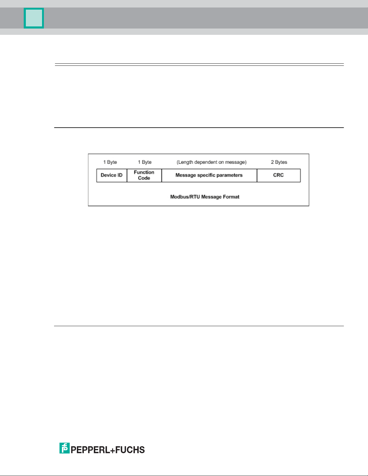
1.3.1. Modbus/RTU
Modbus/RTU is native Modbus in hexadecimal format. These are the base Modbus messages that contain
simple read and write requests. The format is as follows:
Where:
• The terms Master or Client are used to identify the sender of the message.
• The terms Slave or Server are used to identify the devices responding to the message.
Modbus/RTU is used primarily for:
• Serial port connectivity
RS-485 is the most common serial mode, but RS-232 and RS-422 are also widely used. Commonly used
by both Master and Slave devices.
• Ethernet TCP/IP socket connections
This is not the same as Modbus/TCP on Page 8, but does provide a very simple method of interfacing to
remote devices. It is used by many applications and some OPC servers.
Note: This communication method typically is not supported by PLCs.
1.3.2. Modbus/ASCII
Modbus/ASCII is native Modbus in ASCII format. This protocol is used primarily by legacy devices and is no
longer supported as widely as Modbus/RTU.
Like Modbus/RTU, Modbus/ASCII contains the base Modbus messages that contain simple read and write
requests. The differences between Modbus/ASCII and Modbus/RTU are:
1. The message data is sent in ASCII format, so the message length is twice as long. It requires two ASCII
characters for each byte of data.
2. An 8-bit LRC is attached to verify the message instead of a 16-bit CRC. The LRC is also transmitted in
ASCII format.
3. There are defined starting and ending characters to determine a Modbus/ASCII messages.
6/3/19
7
Page 8
ICDM-RX/MOD User Manual
Overview
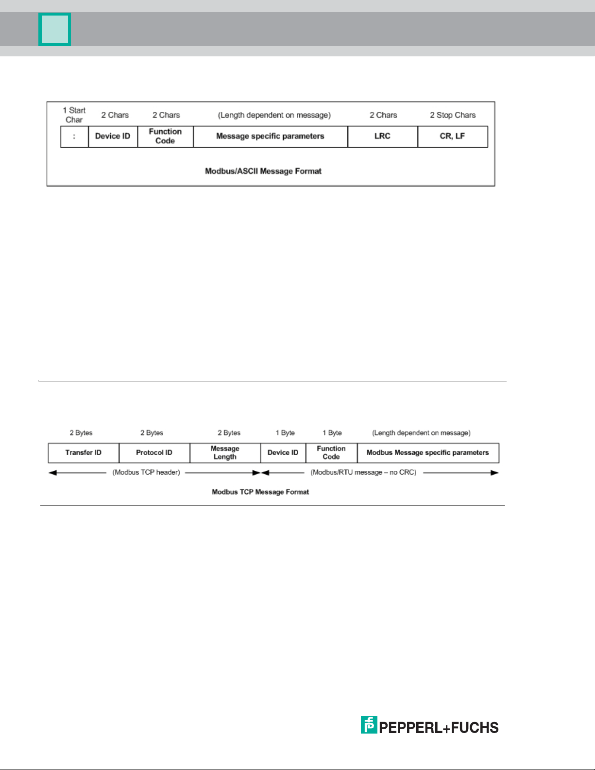
The format is as follows:
Where:
• The terms Master or Client are used to identify the sender of the message.
• The terms Slave or Server are used to identify the devices responding to the message.
Modbus/ASCII is used primarily for:
• Serial port connectivity
RS-485 is the most common serial mode, but RS-232 and RS-422 are also used. Used primarily by legacy
Slave devices.
• Ethernet TCP/IP socket connections
This is not the same as Modbus/TCP, but does provide a very simple method of interfacing to remote
devices. It is used by some applications and some OPC servers.
Note: This communication method typically is not supported by PLCs.
1.3.3. Modbus/TCP
Modbus/TCP is an Ethernet network based protocol that contains a Modbus/RTU message, with the exception
of the 2-byte CRC. The Modbus/TCP message contains a header with information designed to provide
message identification and routing information. The format is as follows:
Where:
• The terms Master or Client are used to identify the sender of the message.
• The terms Slave or Server are used to identify the devices responding to the message.
• Modbus/TCP messages are typically sent to and received on a defined Ethernet TCP/IP socket of 502.
• Modbus/TCP implementations provide more capability, but also require more processing than simpler
Modbus/RTU implementations.
Modbus/TCP is used for connecting advanced Ethernet based devices, such as PLCs, HMIs, SCADA Systems,
and most OPC Servers to:
• Other Ethernet devices supporting Modbus/TCP.
• Remote serial Modbus/RTU and/or Modbus/ASCII devices through gateways (such as the ICDM-RX/MOD
running the Modbus Router or Modbus/TCP applications).
• Remote serial or Ethernet TCP/IP ASCII devices (barcode scanners, printers, RFID readers, visions
systems, etc) through a gateway (such as the ICDM-RX/MOD running the Modbus/TCP application).
6/3/19
8
Page 9

ICDM-RX/MOD User Manual
Overview
1.4. Modbus Router Functionality
The Modbus Router application provides the following functionality:
• Provides robust connectivity from all supported master devices to all supported slave devices:
- Supported Masters:
- Modbus/TCP Master - accepts Modbus/TCP messages on up to eight TCP/IP ports. This includes
502 and seven configurable ports.
- Modbus/RTU Serial Master
- Modbus/ASCII Serial Master
- Modbus/RTU over Ethernet TCP/IP Master
- Modbus/ASCII over Ethernet TCP/IP Master
- Supported Slaves:
- Modbus/RTU Serial Slaves
- Modbus/RTU ASCII Slaves
- Remote Modbus/TCP Slaves (addressable to device ID and IP address/port)
- Remote Modbus/RTU Serial Slaves (via Modbus/TCP using another gateway)
- Remote Modbus/ASCII Serial Slaves (via Modbus/TCP using another gateway)
• Multiple ICDM-RX/MOD chassis can be used together to form a Modbus network.
• Supports up to 255 public Modbus devices per gateway and/or Modbus network. Both standard, (1-247),
and reserved, (248-255), device IDs are supported.
• All Modbus devices not configured remotely are assumed to be locally connected to the gateway.
• The locations of all local Modbus devices are determined automatically.
• Modbus Device ID Aliasing. Modbus message device ID can be aliased when messages are received from
a Modbus master.
• Device ID Offset. At the serial port interface, device IDs can have a positive or negative offset applied to
change the device ID range.
• Supports up to 96 Modbus/TCP connections. This can include any combination of slave and master
connections.
• Modbus/RTU and Modbus/ASCII over Ethernet TCP/IP Master specific:
- Can support up to six TCP/IP connections per serial port configuration.
- All messages received from any Ethernet TCP/IP Master connection enter the routing functionality and
can be routed to any local or remote device.
- Combined with a serial port redirector, such as the Pepperl+Fuchs Comtrol Secure Port Redirector, can
provide COM port functionality from a computer to the Modbus network.
• Supports connectivity to private Modbus serial buses, such as a serial master and slave(s) on a RS-485
loop:
- The Modbus master is provided connectivity to the public Modbus network.
- Only the master has direct access to the serial devices on the private serial network.
- Private slaves are protected from intrusion by other master(s).
- Both slave device specific and port level diagnostics are provided for private network communication.
• Advanced Master-to-Master connectivity is provided via the Shared Memory sub-system. Features are:
- Eight Holding Register blocks containing 200 registers each.
- Eight Coil blocks containing 160 coils each.
- Read access to all master(s) on the Modbus network.
6/3/19
9
Page 10

ICDM-RX/MOD User Manual
Overview
- Block-specific configurable write-access control. For each block, writes can be enabled for all
master(s) or restricted to a specific serial, Modbus/TCP, or Ethernet TCP/IP master.
- Web pages provide configuration, diagnostics, display of block contents and shared memory clearing
capabilities.
• Modbus specific message handling:
- CRC verification of all messages received on the TCP/IP and serial Modbus/RTU interfaces.
- LRC verification of all messages received on the TCP/IP and serial Modbus/ASCII messages.
- Timing out of responses from slave Modbus devices.
- Transfer ID verification of all remote Modbus/TCP messages.
- Parameter checking of all slave responses.
- Broadcast message handling.
• System monitoring to ensure gateway operation:
- Gateway busy.
- Application message time-outs
- Message validity checking.
• Advanced diagnostics web pages:
- Modbus device specific statistics, response timing, and status. Up to 255 Modbus devices, both
attached and remote, can be monitored simultaneously.
- Modbus/TCP diagnostics, connection(s) status, error messages
- Serial port specific statistics and status.
- Serial port message logging.
10
6/3/19
Page 11

ICDM-RX/MOD User Manual
Overview
Supported Connectivity includes:
Modbus Router
Connectivity Grid
Modbus/TCP
Slave (remote
gateway or
slave Modbus/
TCP device)
Local Public
Modbus/RTU
Serial Slave
Local Public
Modbus/ASCII
Serial Slave
Remote
Slave
Devices
Modbus/RTU
Serial Slave (via
remote
gateway)
Modbus/
TCP Master
XX X X X
XX X X X
XX X X X
XX X X X
Modbus/
RTU Serial
Master
Masters
Modbus/
ASCII Serial
Master
Modbus/RTU
Master over
Ethernet TCP/IP
Modbus/ASCII
Master over
Ethernet TCP/IP
Remote
Modbus/ASCII
Serial Slave (via
remote
gateway)
Local Private
Modbus/RTU
Serial Slave
Local Private
Modbus/ASCII
Serial Slave
XX X X X
X
X
6/3/19
11
Page 12
ICDM-RX/MOD User Manual
Overview
12
6/3/19
Page 13

ICDM-RX/MOD User Manual
Overview
1.5. Multiple Gateway Modbus Networks
A multiple gateway Modbus Network is created by combining two or more Modbus slave(s) and master(s) with
two or more ICDM-RX/MODs running the Modbus Router and/or Modbus/TCP firmware applications.
• Typically, at least one chassis will be running the Modbus Router firmware application.
• The Modbus/TCP application can provide connectivity to local or remote serial and Ethernet TCP/IP Raw/
ASCII devices such as barcode scanners, RFID readers, printers, vision systems, and weigh scales.
• All Modbus masters connected to a ICDM-RX/MOD running Modbus Router can communicate to all public
slaves.
The following connectivity can be provided in a Modbus network when using multiple ICDM-RX/MOD chassis
with Modbus Router and Modbus/TCP firmware applications:
Masters
Modbus Network Connectivity
Slave
Devices
Grid
Modbus/TCP Slave
(remote gateway or
slave Modbus/TCP
device)
Local Public Modbus/
RTU Serial Slave
Local Public Modbus/
ASCII Serial Slave
Remote Modbus/RTU
Serial Slave (via remote
gateway)
Remote Modbus/ASCII
Serial Slave (via remote
gateway)
Serial Raw/ASCII
Devices (remote or
local)
Ethernet TCP/IP Raw/
ASCII Devices (remote
or local)
Modbus
/TCP
Master
XXX X X
XXX X X
XXX X X
XXX X X
XXX X X
XXX X X
XXX X X
Modbus/
RTU
Serial
Master
Modbus/
ASCII
Serial
Master
Modbus/RTU
Master over
Ethernet TCP/
IP
Modbus/ASCII
Master over
Ethernet TCP/
IP
Local Private Modbus/
RTU Serial Slave
Local Private Modbus/
ASCII Serial Slave
6/3/19
X
X
13
Page 14
ICDM-RX/MOD User Manual
Overview
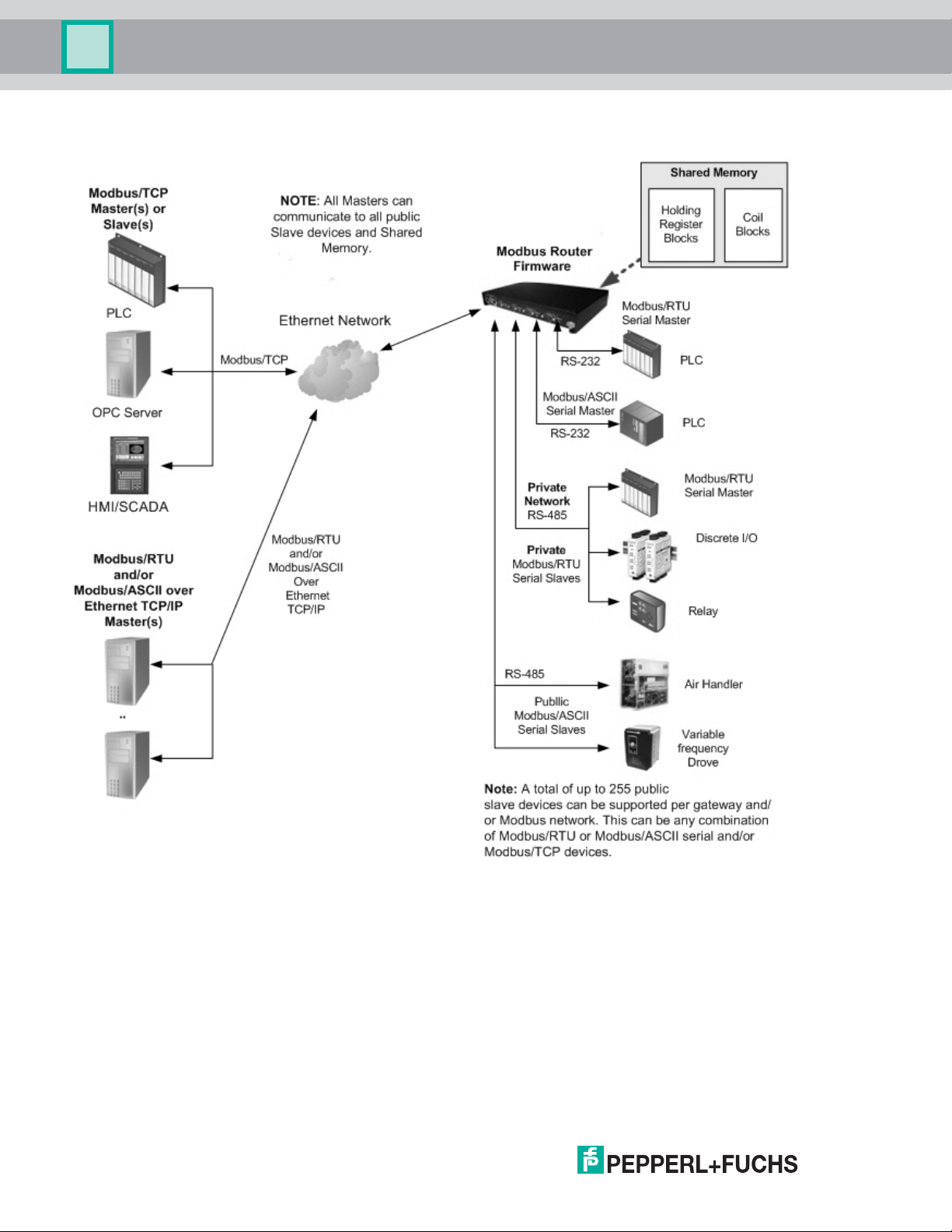
The following diagram demonstrates a multiple gateway Modbus network utilizing Modbus Router firmware.
14
6/3/19
Page 15
ICDM-RX/MOD User Manual
Overview
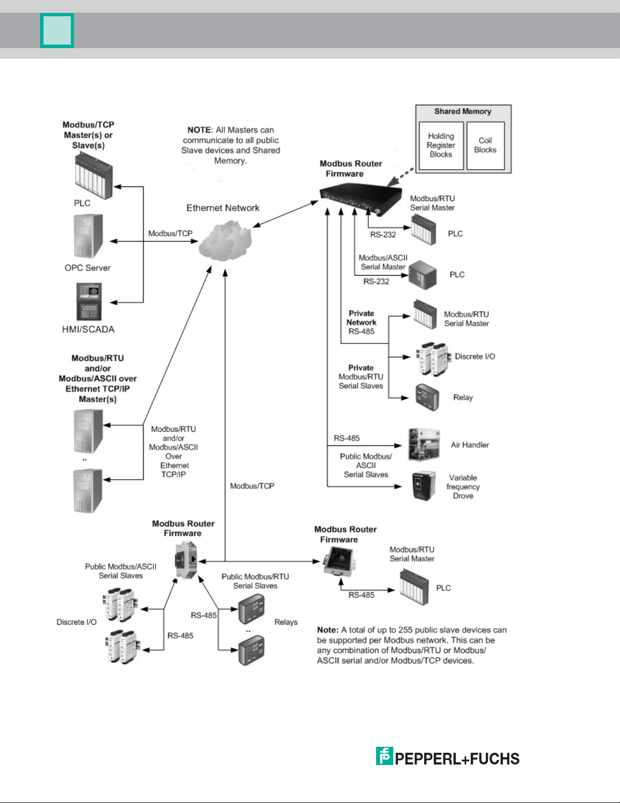
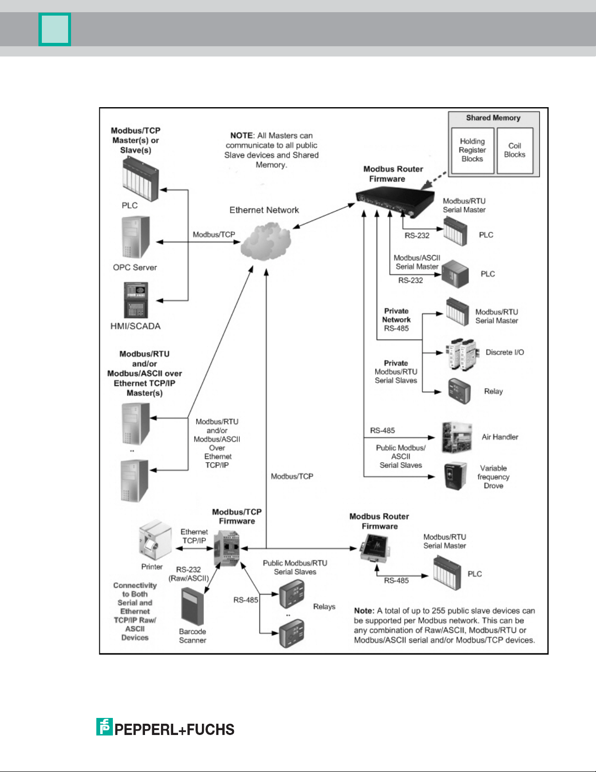
The following diagram demonstrates a multiple gateway Modbus network utilizing both Modbus Router and
Modbus/TCP firmware.
6/3/19
15
Page 16
ICDM-RX/MOD User Manual
Overview
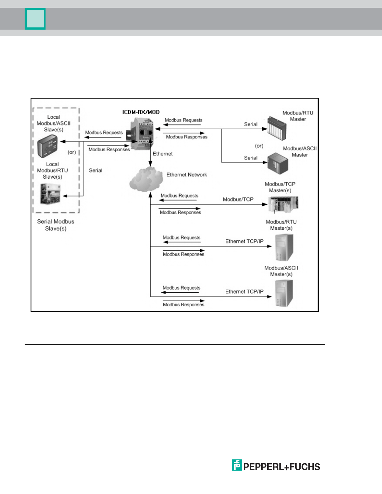
1.6. Modbus/RTU and Modbus/ASCII To-Slaves Interface
The ICDM-RX/MOD provides access to serial Modbus/RTU and Modbus/ASCII slave devices. Modbus master
messages are translated to appropriate Modbus slave messages, public slave devices are automatically
located, and appropriate responses are returned to the Modbus master.
Modbus Master(s) to Public Modbus Slave(s)
1.6.1. Communication Methodology
The ICDM-RX/MOD translates various Modbus formats and forwards them to public slave devices attached to
the Modbus To-Slaves configured serial ports. Each Modbus message is transmitted and a response is
expected. The ICDM-RX/MOD times out the Modbus messages if there is no response returned within the
configured timeout period.
The following diagram displays the Modbus message transfer. The following apply to Modbus To-slaves serial
ports.
• All valid Modbus messages are translated to the appropriate format for serial port or Modbus/TCP
transmission.
• Local public Modbus slave devices are automatically located on a ICDM-RX/MOD 2-port or 4- port.
• Local and remote public Modbus slave devices can be accessed from a Modbus master as if they were of
that master’s protocol type.
• Messages are timed out if no response is returned within the configured timeout period.
16
6/3/19
Page 17

ICDM-RX/MOD User Manual
Overview
• Appropriate Modbus responses are returned to the Modbus master.
• Broadcast Modbus messages, those with a unit identifier of zero, are transmitted out all Modbus To-slaves
serial ports on the ICDM-RX/MOD. Depending on the remote device configuration(s), remote slave devices
may or may not receive broadcast messages.
From a message routing standpoint, all local and remote public Modbus slave devices attached to a ICDM-RX/
MOD gateway (1, 2, or 4-port) must be addressed with unique Unit Identifiers. Valid Unit Identifiers are 1 to 255
and the Broadcast Identifier is zero. However, the Device ID Offset functionality can be configured to change
the addressing of serial connected slave devices to allow multiple slave devices with the same unit ID to be
connected to the same gateway, but addressed differently. For more information, see section on Alias and
Device ID Offset functionality.
To communicate to local Modbus slave device(s) through a ICDM-RX/MOD, perform the following steps.
1. Select the Serial menu and then select the appropriate port.
2. Under Serial Configuration, configure the serial port parameters such as the Mode, Baud rate, Data Bits,
and so forth.
3. Under Modbus Settings, set the Serial Port Protocol to Modbus/RTU-To-Slaves or Modbus/ASCII-To-
Slaves.
4. Under Modbus Slaves To-Slaves Settings, set the Response Timeout to the desired value.
Note: 2- and 4-Port only: Set the Lost Device Search Enable setting. See Local Public Modbus Slave
Device Search Methodology.(below) for more information.
5. If desired, configure the Device ID Offset Mode and Device ID Offset.
To communicate to remote Modbus slave device(s) through a ICDM-RX/MOD, perform the following steps.
1. Select the Modbus menu and then the Remote Modbus Configuration page.
2. Click the Add Remote Configuration button.
3. Configure each remote device as needed and click Save.
To enable the Alias Device ID capability for one or more device Ids, perform the following steps.
1. Select the Modbus menu and then the Alias Configuration page.
2. Click the Add Alias Configuration button.
3. Configure each alias device ID as needed and click Save.
1.6.2. Local Public Modbus Slave Device Search Methodology
Locating a local Modbus slave device on a ICDM-RX/MOD 1-port is relatively simple. Either the Modbus slave
device is connected to the port or it is not. However, if more than one port is configured for Modbus To-Slaves
on a ICDM-RX/MOD 2- or 4-port, the device must be found. The following is an explanation of how the search
algorithm works on a ICDM-RX/MOD 2- or 4-port.
Locating a Local Modbus slave device after a reboot or port reset: When the ICDM-RX/MOD receives a
message for a public Modbus slave device for the first time since reboot or port initialization, it will transmit the
Modbus message out all Modbus To-Slaves serial ports and wait for a response to be returned. Once the
response is returned, the device port is known and all messages sent to the device will be routed through the
serial port.
Lost Devices: Lost devices, or devices that time out, are a special case. The ICDM-RX/MOD provides two
methods for handling lost devices via the Lost Device Search Enable option on the web page.
• Disabling this option on a Modbus To-Slaves port:
- Prevents the ICDM-RX/MOD from searching for a lost device on other Modbus To-Slaves ports.
- Prevents lost devices known to have been on other ports from being searched for on this port.
Note: This is the recommended setting whenever it is desired to prevent timeout delays on other Modbus
To-Slaves ports in the event that a device times out.
• Enabling this option on a Modbus To-Slaves port:
6/3/19
17
Page 18

ICDM-RX/MOD User Manual
Overview
- Allows the ICDM-RX/MOD to search for lost devices on all Modbus To-Slaves ports with the Lost
Device Search Enable option turned on.
- This will cause timeout delays on all Modbus To-Slaves ports with the Device Search Enable option
turned on until the device is found.
Note: This can be useful for locating devices if a device has been moved onto another port by moving the
serial cable or, perhaps, by moving the device onto a different Modbus To-Slaves serial bus.
1.7. Alias Device ID and Device ID Offset Functionality
One of the most common challenges people face when setting up Modbus systems are the problems caused
by the limited device ID range. The Alias Device ID and Device ID Offset functionality have been developed to
help solve those problems.
The Modbus specification has the following limitations:
• Requires all public devices attached to gateway to be addressed by a device ID.
• Allows only 256 device IDs with a range of 0 to 255.
• Not all device IDs can be used for addressing devices.
- Device ID 0 is reserved for broadcast messages
- 1-247 are for device addressing
- 248 to 255 are reserved for such things as gateway functions. Depending on your environment, these
device IDs may or may not be available for assignment to devices.
The following are common problems that can occur as a result of the device ID limitations:
• A gateway must route Modbus messages based on the device ID. Therefore, it cannot route to multiple
Modbus devices with the same device ID.
• It is not always possible or practical to change the device ID of serial Modbus slave devices.
• Serial and Ethernet TCP/IP Modbus RTU/ASCII masters with one connection may need to access multiple
devices with the same device ID. Furthermore, these devices may be located locally or remotely.
• It is not always possible or practical to modify the device IDs on existing Modbus master programs. This is
often true when adding a SCADA system to an existing PLC controlled system.
The Alias Modbus Device ID and Device ID Offset functionality has been developed to solve these problems.
18
6/3/19
Page 19
ICDM-RX/MOD User Manual
Alias Device ID and Device ID Functionality
Overview
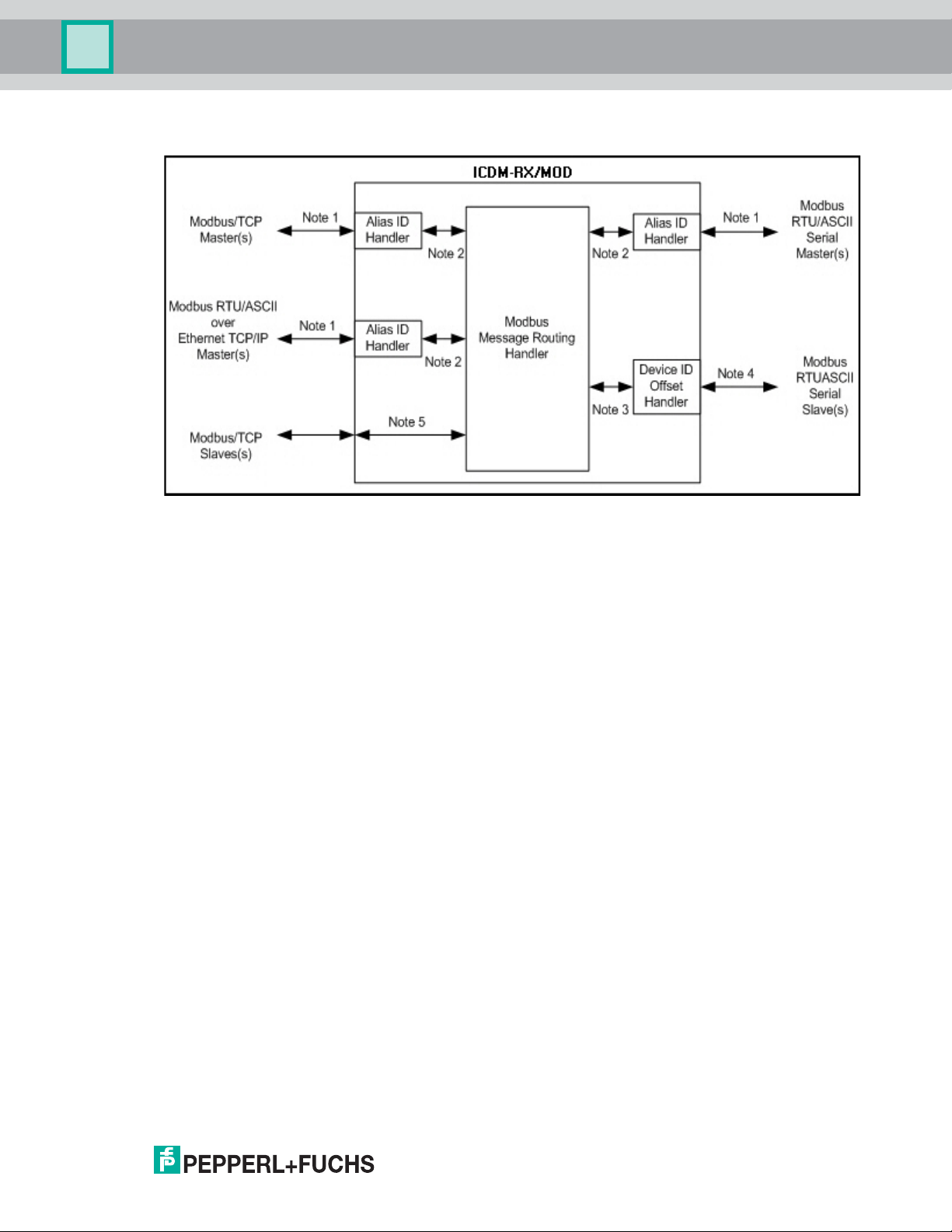
This functionality is described in the following diagram:
Note 1:Originally received Modbus messages. All responses will be returned with the original device ID.
Note 2:Modbus messages sent to and responses received from Modbus Message Routing Handler.
Note 3:Modbus messages received from the Modbus Message Routing Handler. Depending on the Alias
Note 4:Modbus messages sent to Modbus serial slaves. Depending on the Device ID Offset configuration
Note 5:Modbus messages received from the Modbus Message Routing Handler. Depending on the Alias
Depending on the Alias ID configuration, these messages may contain the originally received
device ID or the alias device ID.
ID configuration, these messages may contain the originally received device ID from the Modbus
master or the alias device ID. All responses contain the device ID as received from the Modbus
Message Routing Handler.
for the serial port, these messages may be the same as those received from the Modbus Message
Routing Handler or have a device ID that has been either incremented or decremented to match
the serial device ID range.
ID configuration, these messages may contain the originally received device ID from the Modbus
master or the alias device ID. Device ID Offset functionality does not apply to Modbus/TCP
slaves.
6/3/19
19
Page 20

ICDM-RX/MOD User Manual
Overview
1.7.1. Alias Modbus Device ID Functionality
The Alias Modbus Device ID functionality allows modification of device IDs only when messages are received
from Modbus masters. When configured, a Modbus message from a master with the specified device ID is
converted to the alias device ID, the message is then routed internally using the alias device ID. All responses
are returned to the master with the original received message device ID.
The following table demonstrates several device ID aliasing examples:
Received
Device ID
110 10
50 5 5
100 254 254
10 10 10
Alias Device IDRouted Message
Device ID
Description
Convert messages with received device ID 1 to 10.
Route message with device ID 10.
Convert messages with received device ID 50 to 5.
Route message with device ID 5.
Convert messages with received device ID 100 to 254.
Route message with device ID 254.
Invalid configuration attempt. No change to device ID is
performed.
1.7.2. Device ID Offset Functionality
The Device ID Offset functionality allows modification of device IDs when messages are transmitted to serial
Modbus slave devices. When configured, the Device ID Offset functionality will modify the device ID received in
the message to match the actual device ID range of the serial device(s). The device ID range is effectively either
increased or decreased depending on the serial port Device ID Offset configuration.
The following table demonstrates several Device ID Offset examples:
Device ID Offset
Mode
Off 0 1-255 1-255
Add-to-Msg-ID 50 1-205 51-255
Subtract-from-Msg-ID 100 101-255 1-155
Device ID
Offset
Valid Message
Device ID
Range
Valid Serial
Device ID
Range
Description
Default mode. Device IDs are
unchanged.
Increase device ID range by 50.
Examples:
Device ID 1 is converted to 51
Device ID 10 is converted to 60
Device ID 120 is converted to 170
Decrease device ID range by 100.
Examples:
Device ID 101 is converted to 1
Device ID 150 is converted to 50
Device ID 225 is converted to 125
It is highly recommended to take great care when configuring the Device ID Offset functionality. Verify the
following when configuring the Device ID Offset:
• Check for Device ID overlaps. Be certain that no two devices can have same device ID as recognized by the
internal Modbus Message Routing Handler.
• Check for conflicts with the Alias device ID configuration. The Device ID Offset configuration must coincide
with any Alias device ID configurations.
20
6/3/19
Page 21

ICDM-RX/MOD User Manual
Overview
• Verify the valid device ID ranges are sufficient to address all serial devices.
1.8. Modus Master/Slaves Serial Port Mode (Private Serial Bus)
As of Modbus Router v5.10, Modbus masters and slave(s) can be connected together on the same serial port.
This provides the following benefits:
1. A serial Modbus master can communicate to slaves on its’ own private serial bus as well as public slaves on
a Modbus network. In this configuration, a serial master can communicate to:
a. Modbus RTU/ASCII slave(s) on its own serial bus.
b. Public Modbus RTU/ASCII serial slave(s) connected to the same ICDM-RX/MOD.
c. Modbus/TCP slaves.
d. Remote public Modbus RTU/ASCII serial slave(s) via an Ethernet attached Modbus gateway.
e. All other Modbus master(s) on the Modbus network via the Shared Memory functionality.
2. The Modbus slaves on the serial bus are
a. The slave device(s) are affectively protected from all other Modbus masters on the Modbus network.
b. The master has total control of communication to the slaves on its own serial bus.
c. The master can provide data to/from the slave(s) to the Modbus network, and other Modbus masters,
via the Shared Memory functionality.
3. Deployment can be greatly simplified.
a. An existing serial bus can be left intact, thusly reducing the rewiring effort.
b. The only wiring change is to attach the ICDM-RX/MOD to the bus anywhere there is access.
4. The system can be more fault-tolerant.
a. In the event the ICDM-RX/MOD is powered off, the master and slaves on the serial bus can still
communicate.
b. By preventing other masters from communicating to the slave devices on the serial bus:
• Other masters cannot cause disruptions in communications between the master and slaves on the
serial bus by overloading the gateway.
• Message latency time between the master and slaves is minimized.
5. Maintenance and downtime costs can be minimized with detailed diagnostics web pages provided by the
ICDM-RX/MOD.
private to the master on that serial bus.
6/3/19
21
Page 22

ICDM-RX/MOD User Manual
Overview
The following diagram demonstrates the To-Master/Slaves mode compared to the To-Master and To-Slaves
modes.
1.8.1. Master/Slaves Message Routing
On a serial port configured to Master/Slaves, only the master on the private serial bus has access to the serial
slaves on that serial bus. However, the master can also communicate to public devices and shared memory
anywhere on the Modbus network.
The Serial Interface Configuration web page contains two configuration settings that determine how the serial
bus routing is controlled.
1.8.1.1. Forward Broadcasts From Master Option
If this option is selected, all broadcast messages received on this port will be forwarded to the Modbus network.
If this option is not selected, all broadcast messages received on this serial port will be dropped and only the
private slave devices will receive them.
Note: Make sure that broadcasts should be forwarded before selecting this option. If this option is selected, all
public slave devices on the local Modbus network will receive the broadcast messages and that may
cause unpredictable results.
22
6/3/19
Page 23

ICDM-RX/MOD User Manual
Overview
1.8.1.2. Private Device ID Range Setting
This range defines the expected private slave device ID range on the serial bus.
• Modbus request messages received on this port that are within this device ID range will not be forwarded to
the Modbus network.
• All communication to device(s) in that range must occur between the Modbus master and slave(s) on that
serial bus.
• The private device ID range must not include public device(s) addressed by the serial master. Loss of
communication errors will result if this occurs. It is recommended to use either the Alias and/or the Device
ID Offset functionality to address those cases where a public device ID falls into the private device ID range.
• All received Modbus request messages that are not within the private device ID range or have been
previously detected on the serial bus, will be forwarded to the Modbus network via the ICDM-RX/MOD.
• Responses, including error messages such as timeouts, received from the Modbus network will be
forwarded to the serial master.
• The ICDM-RX/MOD has a built-in auto-detect algorithm for detecting private slave device(s) with ID(s) not
defined within the private device ID range. If a response from such a device is received on the serial bus,
the ICDM-RX/MOD will add that device ID to the private device list and will no longer route those messages
to the Modbus network.
Note: There is a potential race condition if a slave device ID is not within the private device ID range and exists
both as a public device on the Modbus network and as a private device on the serial bus. If this situation
occurs and the public device responds before the private serial device, the master would receive two
responses for that request, with the first response coming from the public device. If the public and
private device responded at the same time, the Modbus master could detect a corrupted response.
However, once the private slave device responds with a valid response, the auto-detect algorithm will
prevent forwarding of additional requests to the Modbus network.
1.9. Shared Memory Functionality
The Shared Memory functionality has been added to provide a simple and robust method for master-to-master
communication.
• The Shared Memory interface contains eight 200 Holding Register blocks and eight 160 Coil blocks.
• All Modbus masters, (Modbus/TCP, serial Modbus RTU/ASCII, and Modbus RTU/ASCII over Ethernet TCP/
IP), can read the contents of the Shared Memory blocks.
• Write access can be controlled to each Holding Register and Coil block. Each block can be configured to
provide all masters write access or be restricted to a port-specific serial master, a Modbus/TCP master or
an Ethernet TCP/IP master.
• The Shared Memory contents can be displayed and cleared via the embedded web pages.
• Diagnostics for each block include read, write and blocked write message counts.
• Blocked write messages are recorded in the Write Violation Log.
This table displays the supported Holding Register Block Function Codes.
Function Code Description
3 Read Holding Registers
6Write Single Register
16 Write Multiple Registers
22 Write Mask Register
23 Read Write Registers
6/3/19
23
Page 24

ICDM-RX/MOD User Manual
Overview
This table shows the supported Coil Block Function Codes.
Function Code Description
1 Read Coils
5 Write Single Coil
15 Write Multiple Coils
24
6/3/19
Page 25

ICDM-RX/MOD User Manual
Overview
Modbus Router Shared Memory Functionality
6/3/19
25
Page 26

ICDM-RX/MOD User Manual
Serial Modbus Masters to Modbus/TCP Slaves
Overview
1.10. Remote Modbus Routing Capabilities
The Modbus Router firmware provides a wide variety of routing options. Combining those options for a specific
installation requires proper configuration of the ICDM-RX/MOD and a thorough understanding of the Modbus
master(s) and slave(s) communication capabilities and requirements.
1.10.1. Serial Modbus Master(s) to Modbus/TCP Slave(s)
This routing configuration provides serial Modbus master(s) connectivity to Modbus/TCP slave(s). This is
applicable when Modbus master(s) are limited to serial port connectivity and require connectivity to Modbus/
TCP slave(s) or remote Modbus serial slave(s).
1.10.2. Modbus over Ethernet TCP/IP Master(s) to Modbus/TCP Slave(s)
The Modbus router application provides Modbus RTU/ASCII over Ethernet TCP/IP master(s) connectivity to
Modbus/TCP slave(s). This is especially useful when deploying Modbus masters, such as many SCADA, HMI
or OPC servers, that do not support Modbus/TCP.
Modbus over Ethernet TCP/IP Masters to Modbus/TCP Slaves
6/3/19
26
Page 27

ICDM-RX/MOD User Manual
Overview
1.10.3. Modbus/TCP Master(s) to Modbus/TCP Slave(s)
This involves providing Modbus/TCP master(s) connectivity to Modbus/TCP slave(s). This is especially useful
when:
• Modbus/TCP master(s), that can open only one or a very limited number of Modbus/TCP connections,
requires connectivity to multiple Modbus/TCP slaves.
• Multiple Modbus/TCP masters require connectivity to Modbus/TCP slave(s) that can accept only one or a
very limited number of Modbus/TCP connections.
• Modbus/TCP master(s), that can send messages only to the standard Modbus/TCP port of 502, require
connectivity to Modbus/TCP slave(s) that accept messages on non-standard port(s), such as 503, 504,
505, or 506.
Modbus/TCP Masters to Modbus/TCP Slaves (with Non-Standard Ports)
Modbus/TCP Masters to Modbus/TCP Slaves (Single Connection Devices)
6/3/19
27
Page 28

ICDM-RX/MOD User Manual
Overview
1.10.4. Device ID Mapping to IP Address/Port/Slave Device IDs
Combining the Alias and Remote Modbus/TCP configurations can provide connectivity between Modbus
master(s) that address slave(s) based on device ID(s) to Modbus/TCP slave(s) which require specific IP
addresses, port numbers and/or alternate device ID(s). This is especially useful when:
• There are multiple Modbus/TCP slaves with the same device ID.
• A Modbus/TCP slave has multiple internal applications that are addressable through:
- Different IP addresses, same port, same device ID
- Different IP addresses, different ports, same device ID
- Same IP address, different ports, same device ID
The following example depicts a typical installation requiring Device ID mapping:
28
Modbus Master Device ID to Slave Modbus/TCP Device Mapping Example
6/3/19
Page 29

ICDM-RX/MOD User Manual
Overview
To implement this Device ID Mapping example, the following web page configuration entries are required on the
Modbus Alias Device ID Configuration page, which is accessed by clicking Modbus | Alias Configuration.
Where:
Parameter Type Description
Rx Device
Alias Device ID
Modbus/TCP Master
Modbus Serial Master
Modbus over TCP Master
Configuration
(1-255)
Configuration
(1-255)
Configuration (yes/
no)
Configuration (yes/
no)
Configuration (yes/
no)
The original, or pre-alias, device ID received from Modbus
master(s). Required.
The corresponding slave device ID. Required.
Enables the Alias conversion from Modbus/TCP masters.
Must be enabled if Modbus/TCP master(s) are present.
Enables the Alias conversion from serial Modbus masters.
Must be enabled if serial Modbus master(s) are present.
Enables the Alias conversion from Modbus over Ethernet
TCP/IP masters. Must be enabled if Modbus over Ethernet
TCP/IP master(s) are present.
6/3/19
29
Page 30

ICDM-RX/MOD User Manual
Overview
Access the Remote Modbus/TCP Device Configuration page, by clicking Modbus | Remote Modbus
Configuation and the following configuration entries are required.
Slave Device 1 Slave Device 2 Slave Device 3 Slave Device 4 Slave Device 5
Device ID (Can be
pre-alias as
received from
master)
Message Device ID
(can be aliased)
Remote IP Address 192.168.0.10 192.168.0.11 192.168.0.12 192.168.0.12 192.168.0.12
Remote IP Port 502 502 502 503 504
Timeout
Dedicated
Connection
Send Writes First No (configurable)
Disable Broadcasts No (configurable)
Route on Pre-Alias
Device ID
12345
1(not aliased) 1 1 1 1
1000 ms
configurable)
No (configurable)
Yes (See note
below)
1000 ms
(configurable)
No
(configurable)
No
(configurable)
No
(configurable)
No (N/A) No (N/A) No (N/A) No (N/A)
1000 ms
(configurable)
No
(configurable)
No
(configurable)
No
(configurable)
1000 ms
(configurable)
No
(configurable)
No
(configurable)
No
(configurable)
1000 ms
(configurable)
No
(configurable)
No
(configurable)
No
(configurable)
If the following conditions are all met then the routing configuration for the pre-alias device ID will be applied to
the message. This includes the Remote IP Address, Remote IP Port, Dedicated Connection, Send Writes First
and Disable Broadcasts options.
1. The Route on Pre-Alias Device ID is enabled in the remote message device ID configuration in this example:
device ID 1.
2. The message device ID has been aliased, or changed from the original device ID.
3. There is a valid remote device configuration entry for the original, or pre-alias, device ID.
30
6/3/19
Page 31

ICDM-RX/MOD User Manual
Overview
The routing decision making process is depicted in the following diagram:
6/3/19
31
Page 32

ICDM-RX/MOD User Manual
Overview
32
6/3/19
Page 33

ICDM-RX/MOD User Manual
Configuration Overview
2. Configuration Overview
This section provides an overview of how to configure the ICDM-RX/MOD and discusses the Home page.
2.1. Prerequisites
Before you can configure Modbus Router on the ICDM-RX/MOD, you must have previously performed the
following steps:
• Installed the hardware.
• Installed PortVision DX.
• Configured the ICDM-RX/MOD IP address using PortVision DX.
Note: If necessary, refer to the ICDM-RX/MOD Hardware Installation and Configuration Guide for the above
procedures.
2.2. Configuration Overview
The following overview shows how to access the ICDM-RX/MOD Router Configuration embedded web pages.
If you have not configured the network information into the ICDM-RX/MOD during initial setup, you must
configure the network information before configuring serial/socket port characteristics. See the PortVision DX
help system for help configuring the network settings.
1. From PortVision DX, highlight the ICDM-RX/MOD that you want to configure and select Webpage.
Note: Optionally, enter the IP address of the device in the Address box of your web browser.
2. Select the appropriate procedure for your environment.
Serial Modbus Master, Slave, or Master/Slaves
a. Click the Serial tab, which defaults to the Serial Port Overview page.
b. Click the port that you want to configure.
c. Change and save the serial port configuration properties as required for your installation.
Ethernet TCP/IP Modbus Master
a. Click the Modbus tab, which displays the Modbus over TCP Overview (not Modbus/TCP) page.
b. Click the socket that you want to configure.
c. Change and save the Ethernet TCP/IP configuration properties as required for the interface.
Modbus/TCP Device
a. Click the Modbus tab, which displays the Modbus over TCP Overview (not Modbus/TCP) page.
b. Click the Modbus/TCP Configuration sub-menu.
c. Change and save the Modbus/TCP configuration properties as required for the device.
Remote Modbus/TCP Device
a. Click the Modbus tab, which displays the Modbus over TCP Overview (not Modbus/TCP) page.
b. Click the Remote Modbus/TCP Device Configuration sub-menu.
6/3/19
33
Page 34

ICDM-RX/MOD User Manual
Configuration Overview
c. Update and save the remote Modbus/TCP configuration properties as required for the device.
Alias Modbus Device ID
a. Click the Modbus tab, which displays the Modbus over TCP Overview (not Modbus/TCP) page.
b. Click the Alias Configuration sub-menu.
c. Click Add Alias Configuration.
d. Configure and save the Alias Modbus Device IDs as required.
Shared Memory
a. Click the Modbus tab, which displays the Modbus over TCP Overview (not Modbus/TCP) page.
b. Click the Shared Memory sub-menu.
c. Configure and save the Shared Memory blocks as required.
3. Remember to click Save to commit the changes and repeat for each interface that requires configuration.
Note: You may want to back up your ICDM-RX/MOD configuration using PortVision DX. Refer to the
PortVision DX help system for information or the appropriate installation document.
2.3. Modbus Router Home
Access the ICDM-RX/MOD Modbus Router Home page from PortVision DX or enter the IP address of the
ICDM-RX/MOD in the Address box of your web browser.
The Home page displays the software version and current network configuration for the ICDM-RX/MOD.
Modbus Router Home Page
Firmware Modbus Router firmware version currently running on the ICDM-RX/MOD.
Device Name
Serial Number The ICDM-RX/MOD serial number.
MAC Address
System Uptime
IP Config Type of IP configuration currently in use (static or DHCP).
IP Address, IP Netmask, IP
Gateway
You can enter a Device Name in the Network | Configuration page, which will
display in this field.
This is the MAC address of this ICDM-RX/MOD, which is located on the
compliance label on the ICDM-RX/MOD.
Displays how long this ICDM-RX/MOD has been on-line since powered on or
rebooted.
IP address, netmask, and gateway configured in the ICDM-RX/MOD.
34
6/3/19
Page 35

ICDM-RX/MOD User Manual
Serial Menus
3. Serial Menus
This section discusses the Serial Port Overview Page and Serial Port Configuration Page on Page 35, which are
located under the Serial menu.
3.1. Serial Port Overview Page
The Serial Port Overview page displays information about the configured serial settings for each port.
Valid Rcvd Msg Device ID Range (1-255) – (1-255): Displays the valid received message device ID range.
Messages with other valid device IDs will not be transmitted out this port. (Informational only.)
Valid On Port Device ID Range (1-255) – (1-255): Displays the valid device ID range for slave devices
connected to the serial port. Slave devices with other device IDs will not be accessible on this port.
(Informational only.)
For additional diagnostic information, see the Diagnostics Menu on Page 48.
3.2. Serial Port Configuration Page
To access the Serial Port Configuration page, click Serial | Port x.
The following tables provide information about serial configuration settings.
Serial Configuration Page
Serial Configuration
Port Name (Default =
blank)
Port Mode (Default =
RS-232)
Baud Rate (Default =
38400)
User-definable string used to describe the serial interface. Valid characters include
a-z, A-Z, 0-9, underscores, spaces and dashes. All other characters are
discarded. The Port Name supports up to an 80 character ASCII string.
All panel or rack mount models:
• RS-232 (default)
• RS-485
• RS-422
All DIN rail models:
• RS-232 (default)
• RS-422
• RS-485_2-wire
• RS-485_4-wire_Master
• RS-485_4-wire_Slave
300, 600, 1200, 2400, 4800, 9600, 19200, 38400, 57600, 115200, and 230400
6/3/19
35
Page 36

ICDM-RX/MOD User Manual
Serial Menus
Serial Configuration Page (Continued)
Parity
(Default = None)
Data Bits (Default = 8) 5, 6, 7, 8
Stop Bits (Default = 1) 1 or 2
Flow Control (Default =
None)
Terminating Resistor
(Only displays on
applicable models)
DTR Mode (Default =
Off)
Rx Timeout Between
Packets (ms) (Default =
200)
Discard Rx Packets With
Errors (Default = On)
None
Even
Odd
RTS/CTS
XON /XOF F
Half Duplex
To ensure the best signal integrity on a long distance high-speed RS-422 or RS485 network, sometimes it is required to place a 120Ω termination resistor
between each of the transmit differential pair or receive differential pair. Signal
reflection is reduced and a reliable communication is ensured by placing the 120Ω
termination resistor. Using the software, you can place 120Ω termination resistors
between the signals shown below:
• RS-422 Mode
- Between TxD+ and TxD- (Pin 5 and 7)
- Between RxD+ and RxD- (Pin 4 and 2)
• RS-485 - Between TxD/RxD+ and TxD/RxD- (Pin 5 and 7)
0=Off
1=On
Receive time-out (0-65535) between packets in msec. This is the maximum
spacing between received bytes allowed before the received Modbus serial
message is expected to be complete.
On or Off: If selected, the ICDM-RX/MOD drops all packets received with parity,
framing, or overrun errors.
Note: Modbus/RTU messages with invalid CRCs and Modbus/ASCII messages
without correct start and end of transmission characters are always
discarded independent of this setting.
Modbus Settings
Serial Port Protocol
(Default = Modbus/RTUto-Slaves)
36
The Modbus Protocol, setting for this serial port:
• Modbus/RTU-to-Slaves – Configures the serial port to communicate to
Modbus/RTU slaves.
• Modbus/ASCII-to-Slaves – Configures the serial port to communicate to
Modbus/ASCII slaves.
• Modbus/RTU-to-Master – Configures the serial port to communicate to a
Modbus/RTU master.
• Modbus/ASCII-to-Master – Configures the serial port to communicate to a
Modbus/ASCII master.
• Modbus/RTU-to-Master/Slaves – Configures the serial port to communicate to
a serial bus with a Modbus/RTU master and Modbus/RTU slave(s).
• Modbus/ASCII-to-Master/Slaves – Configures the serial port to communicate
to a serial bus with a Modbus/ASCII master and Modbus/ASCII slaves.
6/3/19
Page 37

ICDM-RX/MOD User Manual
Serial Menus
Serial Configuration Page (Continued)
Modbus To-Slaves Settings
Response Timeout
(Default = 1000 msec)
Lost Device Search
Enable
Not supported: 1-port
(Default = Off)
Inactivity Wait Time
Before Tx (ms) (Default
= 0 ms)
Send Write Messages
First (Default = Off)
Disable Writes (Read
Only) (Default = Off)
Device ID Offset Mode
(Default = Off)
Device ID Offset
Modbus To-Master Settings
The maximum allowable time (0 to 65535 msec.) for a slave device to respond to a
message before the message is considered timed out.
If selected, lost devices that were on this port are searched for on other Modbus/
RTU and Modbus/ASCII slave ports that also have this option set.
The minimum time (0 to 65535 msec.) that the ICDM-RX/MOD waits after
receiving a response or transmitting a Modbus request before transmitting the next
request.
If selected, it transmits any write messages before transmitting any read messages
that may have already been queued for transmission.
If selected, it disables transmission of all standard Modbus write messages.
• Off disables Device ID Offset functionality.
• Add-to-Msg-ID adds the Device Offset to the message device ID.
• Subtract-from-Msg-ID subtracts the Device ID Offset from the message device
ID.
• 0 = disables Device ID Offset functionality.
• 1-254 = dependent on the Device ID Offset Mode, is added to or subtracted
from the message device ID before the Modbus message is transmitted out
the serial port.
Discard Modbus Errors
(Default = Off)
Modbus Master/Slave Settings
Forward Broadcasts
from Master (Default =
Off)
Private Slave Device ID
Range (Default: Min = 1,
Max =1)
6/3/19
If selected, all broadcast messages from the serial master will be forwarded to the
Modbus network through the ICDM-RX/MOD.
If selected, all broadcast messages from the serial master will be forwarded to the
Modbus network through the ICDM-RX/MOD.
This range (1-255) defines the expected slave device ID range on the serial bus.
Modbus request messages received on this port within this device ID range will not
be forwarded to the Modbus network.
Note: The ICDM-RX/MOD has a built-in auto-detect algorithm for detecting
For a more complete discussion, refer to Modus Master/Slaves Serial Port Mode
(Private Serial Bus) on Page 21.
Note: The minimum value must be less than or equal to the maximum value.
private slave device(s) with ID(s) not defined within the private device ID
range.
37
Page 38

4. Modbus Menus
This section discusses the Modbus configuration pages:
• TCP/IP Configuration Pages on Page 38
• Modbus/TCP Configuration Page on Page 39
• Remote Modbus/TCP Device Configuration Page on Page 40
• Modbus Alias Device ID Configuration Page on Page 41
• Shared Memory Configuration Page on Page 41
4.1. TCP/IP Configuration Pages
This subsection discusses the Modbus over TCP Overview (not Modbus/TCP) Page and Modbus over TCP (not
Modbus/TCP) Socket Configuration Page for the Ethernet TCP/IP interface.
Each Ethernet TCP/IP interface provides connectivity to either Modbus/RTU or Modbus/ASCII masters. All request
messages received from the Ethernet TCP/IP interface are forwarded to the routing process which, in turn, forwards
the messages to either local or remote Modbus slave devices.
Note: The Ethernet TCP/IP interfaces are not directly tied to a serial port. All messages received over the Ethernet
TCP/IP interface receive the same local and remote routing capabilities as messages received over the
Modbus/TCP or serial Master interfaces.
4.1.1. Modbus over TCP Overview (not Modbus/TCP) Page
Access the Modbus over TCP Overview (not Modbus/TCP) page by clicking Modbus | TCP/IP Configuration and the
following page appears. This page provides an overview of the settings for each socket.
4.1.2. Modbus over TCP (not Modbus/TCP) Socket Configuration Page
Access the Modbus over TCP (not Modbus/TCP Socket Configuration page by clicking Modbus | TCP/IP
Configuration | Socket x. The following table provides information about each configuration setting.
Modbus over TCP (not Modbus/TCP) Socket Configuration Page
TCP Configuration
• Modbus/RTU-to-Master – Configures the TCP/IP connection(s) to
Connect To Mode
Enable (Default = Off) If selected, this TCP/IP socket interface will be enabled.
Listen (Default = Off)
communicate to Modbus/RTU master(s).
• Modbus/ASCII-to-Master – Configures the TCP/IP connection(s) to
communicate to Modbus/ASCII master(s).
If selected, the TCP/IP socket interface will listen for a connection at the specified
Listen Port.
Modbus Menus ICDM-RX/MOD User Manual: DOCT-6444 Rev. A - 38
Page 39

ICDM-RX/MOD User Manual
Modbus Menus
Modbus over TCP (not Modbus/TCP) Socket Configuration Page (Continued)
The Listen Port values are 1-65535.
Listen Port
(Defaults:
Port 1=8000
Port 2=8001
Port 3=8002
Port 4=8003)
Connect to Mode (Default
= Never)
Connect Port (Default = 0)
Connect IP Address
(Default = 0)
Disconnect Mode (Default
= Never)
Idle Timer (Default = 0)
Rx Timeout Between
Packets (Default = 100)
If Enable and Listen are both selected, allows acceptance of:
• Up to six connections from external applications if there is no active Connect-
to connection.
• Up to five connections if there is an active Connect-to connection.
Note: The defined Modbus/TCP socket port of 502 will not be accepted as valid
configuration data.
• If Enable is selected, this setting determines how to connect to an
application.
• If Never: Do not attempt to make a connection.
• If Connect-Always: Always attempt to maintain a connection to the
application at Connect IP Address and Connect Port.
Socket port to connect to (1 to 65535). Used in conjunction with Connect to Mode
and Connect IP Address.
IP Address of application to create a connection. Used in conjunction with
Connect to Mode and Connect Port.
Note: The IP Address of this ICDM-RX/MOD will not be accepted as valid
configuration data.
Mode on which to disconnect from the application.
• Never – Will not disconnect when connection(s) are idle.
• Idle – Utilizes the Idle Timer to determine when to close the connection.
If the Disconnect Mode is set to Idle, the idle or inactivity time (1 to 65535 ms)
when the connection(s) will be closed.
Receive timeout (0-65565) between packets in msec. This is the maximum
spacing between received bytes allowed before the received Modbus message
is expected to be complete.
4.2. Modbus/TCP Configuration Page
Access the Modbus/TCP Interface Configuration page by clicking Modbus | Modbus/TCP Configuration. The
following table provides information about each configuration setting.
Modbus/TCP Configuration Page
Modbus TCP/IP Port 1
Enabled Always enabled. Cannot be disabled.
TCP/IP Port The standard Modbus TCP/IP port of 502. This port is always enabled.
Modbus TCP/IP Ports 2 to 16
Enabled
(Default: No)
6/3/19
If selected, the ICDM-RX/MOD will listen for Modbus/TCP requests on the
configured TCP/IP port.
39
Page 40

ICDM-RX/MOD User Manual
Modbus Menus
Modbus/TCP Configuration Page (Continued)
TCP/IP Port
Default Port 2 = 503
Default Port 3 = 505
Default Port 4 = 506
Default Port 5 = 507
Default Port 6 = 508
Default Port 7 = 509
Default Port 8 = 510
The specified TCP/IP port(1-65535) that the ICDM-RX/MOD will listen for Modbus/
TCP requests on.
Default ports are the first seven unassigned ports, as determined by the Internet
Assigned Numbers Authority after the standard Modbus/TCP port of 502.
Note: TCP/IP ports 0, 22, 23, 80, 443, 4606 and 4607 are not allowed. Enabling
TCP/IP ports other than the defaults may cause disruptions on your
network. Please verify any configuration changes with your IT department.
4.3. Remote Modbus/TCP Device Configuration Page
All Modbus devices not configured remotely are assumed to be local, or connected to this gateway. The
location of all local Modbus devices is determined automatically. Access the Remote Modbus/TCP Device
Configuration page by clicking Modbus | Remote Modbus Configuration. Click the Add Remote Configuration
button to add additional remote devices.
The following table provides details about configuration options.
Remote Modbus/TCP Device Configuration Page
Device ID #
Remote IP Address
Remote Modbus/TCP
Port (Default = 502)
Timeout (ms)
(Default = 1000 msec)
Dedicated Connection
(Default = Off)
Send Writes First
(Default = Off)
Disable Broadcast
Messages (Default =
Off)
The Device ID (also often called the unit ID) of the remote device must be unique.
The Device ID range is 1-255. 0 means that it is not configured.
IP address of the Modbus/TCP device. All 0s means that it is not configured.
Note: The IP address of the ICDM-RX/MOD will not be accepted as valid
configuration data.
The TCP/IP port (1-65535) to connect to on the remote device.
The maximum allowable time (0 to 65535 msec) for a slave device to respond to a
message before the message is considered timed out.
If selected, a dedicated Modbus/TCP connection will be used to connect to this
remote device.
Note: This is most commonly used when connecting to another gateway, multiple
devices are being accessed, and maximum bandwidth is desired.
If selected, will forward write messages before forwarding any pending read
messages.
Note: This is most commonly used when multiple messages may be outstanding
for the remote device(s) and low latency for write messages is desired.
If selected, will disable broadcasts to this remote device.
Note: If multiple remote devices are accessed through another gateway, then
this option must be selected for all remote devices configured to that
gateway to prevent broadcast messages from being sent to those devices.
40
6/3/19
Page 41

ICDM-RX/MOD User Manual
Modbus Menus
Remote Modbus/TCP Device Configuration Page (Continued)
This setting only applies to a Modbus message if the following two statements are
true:
• The Modbus message device ID has been aliased, or changed, as a result of a
corresponding Alias Device ID configuration via the Modbus Alias Id
Route on Pre-Alias
Device ID (Default = Off)
Delete If enabled, that Device ID or IDs are deleted when you click the Save button.
Configuration page.
• A Remote Modbus/TCP Device configuration exists for the pre-aliased, or
original, device ID.
If selected and all requirements are true, then the Remote Device ID configuration
for the pre-aliased device ID will be applied to the Modbus message. This includes
the IP address/port, timeout and control flags.
4.4. Modbus Alias Device ID Configuration Page
You can configure up to four alias device IDs at one time.
Access the Modbus Alias Device ID Configuration page by clicking Modbus | Alias Configuration.
The following configuration options apply:
Modbus Alias Device ID Configuration Page
Rx Device ID
Alias Device ID
Modbus/TCP Master
(Default = Off)
Modbus Serial Master
(Default = Off)
Modbus over TCP Master
(Default = Off)
The device ID (also often called the unit ID) of the received
message from a master. Device IDs range from 1 to 255.
The alias device ID to convert the received device ID to. Alias
Device IDs range from 1 to 255.
If selected, this applies the alias device ID configuration to
messages received from Modbus/TCP masters.
If selected, this applies the alias device ID configuration to
messages received from serial Modbus masters.
If selected, this applies the alias device ID configuration to
messages received from Modbus RTU/ASCII over Ethernet TCP/IP
masters.
4.5. Shared Memory Configuration Page
Access the Shared Memory Configuration page by clicking Modbus | Shared Memory.
The following table displays the supported Holding Register Block function codes.
Holding Register Block Function Codes
3 Read Holding Registers
6Write Single Register
16 Write Multiple Registers
22 Write Mask Register
23 Read Write Registers
6/3/19
41
Page 42

ICDM-RX/MOD User Manual
Modbus Menus
This shows the supported Coil Block function codes.
Coil Block Function Codes
1 Read Coils
5 Write Single Coil
15 Write Multiple Coils
The following table provides details about the configuration options. Click the Display button to view detailed
information about a specific block or coil.
Shared Memory Configuration Page
Enable Shared Memory
(Default = Off)
Shared Memory Device
ID (Default = 252)
Holding Register Start
Address (Base 1)
(Default = 400001)
Coil Block Start Address
(Base 1) (Default = 1)
Shared Holding Registers
Block Specifies the block number.
Address Range Specifies the block address range.
Accept Broadcast
Messages (Default = No)
Write Master(s) (Default
= All)
Serial Port / IP Address
Description
If selected, enables the Shared Memory functionality.
The Device ID (also often called the unit ID) of the Shared Memory must be
unique within the public Modbus network. The Device ID range is 1 to 255.
Specifies the starting address of the Shared Memory Holding Register
blocks. The range is 400001 to 463935.
Specifies the starting address of the Shared Memory Coil blocks. The range
is 1 to 64255.
If selected, the Shared Memory block(s) will accept broadcast messages
addressed to their memory block(s).
Indicates which master(s) have write access to the Shared Memory block.
• All – All masters have write access to the block
• Port specific serial master:
- Port-1
- Port-2 (2-port and 4-port models only)
- Port-3 (4-port models only)
- Port-4 (4-port models only)
• Ethernet based masters:
- Modbus/TCP - Modbus/TCP master(s) at a specified IP address
- Ethernet TCP/IP – Ethernet TCP/IP master(s) at a specified IP
address
IP address of the Modbus/TCP or Ethernet TCP/IP master. Zeros indicate
that there is no configuration.
Note: Does not apply to All or port-specific serial masters.
User-defined description of the Shared Memory block. ASCII string with a
maximum of 80 characters in length.
Shared Coils
Block Specifies the block number.
Coil Range Specifies the coil range.
42
6/3/19
Page 43

ICDM-RX/MOD User Manual
Modbus Menus
Shared Memory Configuration Page (Continued)
Accept Broadcast
Messages (Default = No)
Write Master(s) (Default
= All)
Serial Port / IP Address
Description
If selected, the Shared Memory block(s) will accept broadcast messages
addressed to their memory block(s).
Indicates which master(s) have write access to the Shared Memory block.
• All – All masters have write access to the block
• Port specific serial master:
- Port-1
- Port-2 (2-port and 4-port models only)
- Port-3 (4-port models only)
- Port-4 (4-port models only)
• Ethernet based masters:
- Modbus/TCP - Modbus/TCP master(s) at a specified IP address
- Ethernet TCP/IP – Ethernet TCP/IP master(s) at a specified IP
address
IP address of the Modbus/TCP or Ethernet TCP/IP master. Zeros indicate
that there is no configuration.
Note: Does not apply to All or port-specific serial masters.
User-defined description of the Shared Memory block. ASCII string with a
maximum of 80 characters in length.
6/3/19
43
Page 44

ICDM-RX/MOD User Manual
Network Menu
5. Network Menu
This section discusses the pages under the Network menu, which includes:
• Network Configuration Page on Page 44
• Password Page on Page 45
• Security Page on Page 45
• Keys/Certs Page on Page 46
5.1. Network Configuration Page
You can use the Network Configuration page to change the ICDM-RX/MOD network configuration after using
PortVision DX for initial network configuration.
Click the Network tab to access this page.
The following table provides information about the Network Configuration fields.
General
Host Name
TCP Keepalive
Default = 60
Boot Timeout
Default = 15
IP Configuration (IPv4)
Use DHCP
You can enter a 16-character Host Name to identify this ICDM-RX/MOD on the Home
page.
The TCP protocol has a keepalive feature where the two network stacks periodically
ping each other to make sure the connection is still up.
Upon loss of a TCP/IP connection, the network stack starts a timer. If the TCP/IP
connection is still lost after the number of seconds set by the TCP Keepalive value,
then the ICDM-RX/MOD closes the connection and frees all the ports associated
with the connection.
If the ICDM-RX/MOD was the originator of the first connection, it will then try to reconnect the TCP/IP connection. This allows the ICDM-RX/MOD to be connected
and ready to send/receive data even after a network disturbance.
For most networks the default value should not need to be changed.
Allows you to change the bootloader time-out value before the default application,
Modbus Router loads.
You may need to increase this time-out value to 45 for compatibility with spanning
tree devices (normally switches). If you change the time-out value to 0, this prevents
Modbus Router from loading.
Configures the ICDM-RX/MOD to use DHCPv4 mode.
If you select Use DHCP, the IPv4 Address field below is disabled and set to 0.0.0.0.
See your System Administrator to acquire a unique reserved IPv4 address if you are
using DHCP. They will need the MAC address of the unit to provide you with an IPv4
address.
Network Configuration Page
44
6/3/19
Page 45

ICDM-RX/MOD User Manual
Network Menu
Network Configuration Page
Configures the ICDM-RX/MOD with the static IPv4 address information that you
provide in the IPv4 Address, IPv4 Netmask, and IPv4 Gateway fields below.
Use static
configuration
below
The ICDM-RX/MOD is shipped from the factory with the following default IPv4
network settings:
• IPv4 address = 192.168.250.250
• IPv4 Netmask = 255.255.0.0
• IPv4 Gateway address = 192.168.250.1
5.2. Password Page
You can easily set up a password to secure the ICDM-RX/MOD.
There is no password set from the factory.
Use the following information to configure a password for this ICDM-RX/MOD.
1. If necessary, click Network | Password.
2. If changing an existing password, enter that password in the Old Password field.
3. Enter a new password.
4. Enter the password in the Confirm New Password field.
5. Click the Save button.
To log into the ICDM-RX/MOD, you must enter the following:
• admin for the username
• The configured password for the password
5.3. Security Page
The following table discusses Security Settings options.
Security Settings Page
If Secure Config mode is enabled, unencrypted access to administrative and
diagnostic functions is disabled. Secure Config mode changes ICDM-RX/MOD
behavior as follows:
• Telnet access to administrative and diagnostic functions is disabled. SSH
access is still allowed.
Enable Secure Config
Mode
6/3/19
• Unencrypted access to the web server via port 80 (http:// URLs) is disabled.
Encrypted access to the web server via port 443 (https:// URLs) is still allowed.
• Administrative commands that change configuration or operating state which
are received using the Pepperl+Fuchs Comtrol proprietary TCP driver protocol
on TCP port 4606 are ignored.
• Administrative commands that change configuration or operating state that are
received using the Pepperl+Fuchs Comtrol MAC mode proprietary Ethernet
protocol number 0x11FE are ignored.
45
Page 46

ICDM-RX/MOD User Manual
Network Menu
Security Settings Page (Continued)
Enable Telnet/ssh
Enable SNMP
Minimum Allowed
SSL/TLS Version
Use the following steps to change security settings in the ICDM-RX/MOD.
1. Click the Network | Security.
2. Click the appropriate check boxes in the Security Settings page to enable or disable security accordingly.
3. After making changes, you must click Save.
4. You may need to configure security keys or certificates depending on your choices using the next
subsection.
This option enables or disables the telnet security feature after you click Save and
the ICDM-RX/MOD has been rebooted. This option is enabled by default.
This option enables or disables the SNMP security feature after you click Save and
the ICDM-RX/MOD has been rebooted. This option is enabled by default.
You can select the appropriate version for your environment.
• SSLv3.0
• TLSv1.0 (default)
• TLSv1.1
• TLSv1.2
5.4. Keys/Certs Page
For secure operation, the ICDM-RX/MOD uses a set of three keys and certificates. These keys and certificates
are user configurable.
Note: All ICDM-RX/MOD units are shipped from the factory with identical configurations. They all have the
identical self-signed, Pepperl+Fuchs Comtrol Server RSA Certificates, Server RSA Keys, and Server
DH Keys.
For maximum data and access security, you should configure all ICDM-RX/MOD units with custom
certificates and keys.
Key and Certificate Management Page
This is a private/public key pair that is used for two purposes:
• It is used by some cipher suites to encrypt the SSL/TLS handshaking
messages. Possession of the private portion of this key pair allows an
eavesdropper to both decrypt traffic on SSL/TLS connections that use RSA
encryption during handshaking.
RSA Key pair used by SSL
and SSH servers
• It is used to sign the Server RSA Certificate in order to verify that the ICDM-
RX/MOD is authorized to use the server RSA identity certificate.
Note: Possession of the private portion of this key pair allows somebody to
pose as the ICDM-RX/MOD.
If the Server RSA Key is to be replaced, a corresponding RSA identity certificate
must also be generated and uploaded or clients are not able to verify the identity
certificate.
6/3/19
46
Page 47

ICDM-RX/MOD User Manual
Network Menu
Key and Certificate Management Page (Continued)
This is the RSA identity certificate that the ICDM-RX/MOD uses during SSL/TLS
handshaking to identify itself. It is used most frequently by SSL server code in
the ICDM-RX/MOD when clients open connections to the ICDM-RX/MOD's
secure web server or other secure TCP ports.
RSA Server Certificate
used by SSL servers
DH Key pair used by SSL
servers
Use the following steps to update security keys and certificates in the ICDM-RX/MOD.
1. Click the Network | Keys/Cert.
2. Click Browse to locate the key or certificate file, highlight the file, and click Open.
3. Click Upload when you return to the Key and Certificate Management page.
The key or certificate notation changes from factory or none to User when the ICDM-RX/MOD is secure.
Note: You do not need to click Save, but changes will not take effect until the ICDM-RX/MOD is rebooted.
If a ICDM-RX/MOD serial port configuration is set up to open (as a client) a TCP
connection to another server device, the ICDM-RX/MOD also uses this
certificate to identify itself as an SSL client if requested by the server.
In order to function properly, this certificate must be signed using the Server
RSA Key. This means that the server RSA certificate and server RSA key must
be replaced as a pair.
This is a private/public key pair that is used by some cipher suites to encrypt the
SSL/TLS handshaking messages.
Note: Possession of the private portion of the key pair allows an eavesdropper
to decrypt traffic on SSL/TLS connections that use DH encryption during
handshaking.
6/3/19
47
Page 48

ICDM-RX/MOD User Manual
Diagnostics Menu
6. Diagnostics Menu
The following pages are located under the Diagnostics menu:
• Serial Communication Statistics Page on Page 48
• Modbus RTU/ASCII over Ethernet TCP Statistics Page on Page 49
• Serial Interface Logs Page on Page 50
• Known Modbus Slave Device List Page on Page 50
• Modbus/TCP and Serial Modbus Master Statistics Page on Page 52
• Modbus/TCP Connections Page on Page 54
• Modbus Alias Device ID Statistics Page on Page 55
• Shared Memory Contents Page on Page 55
• System Log Page on Page 57
6.1. Serial Communication Statistics Page
Click Diagnostics | Communication | Serial Statistics to access the Serial Communication Statistics page.
The following table provides detailed information about the Serial Communications Statistics page.
Serial Communication Statistics Page
TX Byte Count (To Device) Displays the number of bytes transmitted out the serial port.
TX Message/Response Count
RX Byte Count (From Device) Displays the number of bytes received on the serial port.
RX Message/Response Count
TX or RX Broadcast Msg Count
Master/Slaves Private Messages
Parity Error Count
Framing Error Count
Overrun Error Count
Displays the number of messages or responses transmitted out of the
serial port.
Displays the number of messages or responses received on the serial
port.
Displays the number of broadcast messages transmitted out the serial
port.
Displays the number of private messages detected, those between a
master and private slave(s), on a serial port configured in Master/Slaves
mode.
Displays the number of parity errors received on the serial port. Typically
occurs due to an incorrect parity setting.
Displays the number of framing errors received on the serial port.
Typically occurs due to an incorrect baud rate or stop bit setting.
Displays the number of overrun errors received on the serial port. This
typically occurs to one of the following events: incorrect flow control,
incorrect baud rate, incorrect data size, or incorrect stop bit setting.
48
6/3/19
Page 49

ICDM-RX/MOD User Manual
Diagnostics Menu
Serial Communication Statistics Page (Continued)
Displays the number of messages or responses dropped to any of the
following:
Dropped Message/Response
Count
Invalid Message/Response
Count
Device Timeouts
Blocked Write Messages
• Incomplete message or response.
• Did not receive valid start and/or end characters (Modbus/ASCII
Displays the number of invalid messages or responses received to any of
the following events:
• Message received after the timeout period. This may require
• Incorrect device ID in response message.
• Incorrect function code in response message.
Displays the number of device timeouts that occurred when there was no
response for a Modbus message.
Displays the number of Modbus write messages that were not
transmitted as a result of the Disable Writes (Read Only) option being set.
only).
increasing the Device Response Timeout.
6.2. Modbus RTU/ASCII over Ethernet TCP Statistics Page
Click Diagnostics | Communication | TCP Statistics to access the Modbus RTU/ASCII over Ethernet TCP
Statistics page.
The following table provides information about Ethernet TCP/IP interface statistics on the Modbus RTU/ASCII
over Ethernet TCP Statistics page.
Modbus RTU/ASCII over Ethernet TCP Statistics Page
TX Byte Count (To Application) The number of bytes transmitted out of the TCP/IP connection(s).
TX Response Count The number of responses transmitted out of the TCP/IP connection(s).
The number of responses that were intended to be transmitted out the
Dropped TX Responses
RX Byte Count (From
Application)
RX Message Count The number of messages received on the TCP/IP connection(s).
Dropped RX Messages Due to
Congestion
Dropped Invalid or Incomplete RX
Messages
Dropped RX Messages Due to
Invalid CRCs
Remote Connection Status Displays remote TCP/IP connections.
TCP/IP connection(s) but could not be and were dropped. This typically
occurs when one or more connections close unexpectedly.
The number of bytes received on the TCP/IP connection(s).
The number of messages that were dropped to the gateway being overly
congested. This typically occurs when the application(s) send messages
faster than the slave device(s) can respond.
The number of messages from the application(s) that were dropped to:
• Containing an invalid Modbus message format.
• Containing an incomplete Modbus message.
The number of messages from the application(s) that were dropped due to
an invalid Modbus/RTU CRC or Modbus/ASCII LRC.
6/3/19
49
Page 50

ICDM-RX/MOD User Manual
Diagnostics Menu
6.3. Serial Interface Logs Page
This page displays the serial messages transmitted and received during normal operation. Click Diagnostics |
Communication | Serial Logs to access this page.
The format is as follows:
Pkt(N): ddd:hh:mm:ss.mss Rx/Tx>(data packet)
Where:
ddd – days since last system restart
hh – hours since last system restart
mm – minutes since last system restart
ss – seconds since last system restart
mss – milliseconds since last system restart
(data) – Modbus/RTU or Modbus/ASCII message data.
• Private messages between the master and slaves on the Master/Slaves ports are indicated with “(Private)”.
• All other messages are those routed through the Modbus gateway to the Modbus network or Shared
Memory.
6.4. Known Modbus Slave Device List Page
The Known Modbus Slave Device List page provides device specific status and statistics for each device
connected locally to one or more of the serial ports or remotely through a remote Modbus/TCP device
configuration.
Access the Known Modbus Slave Device List page by clicking Diagnostics | Modbus Diagnostics | Modbus
Devices.
The following table provides detailed information about this page.
Known Modbus Slave Device List Page - Public Devices
Displays the device ID associated with this device.
Device ID
Active?
IP Address
IP Port
Tx Req Displays the number of Modbus messages transmitted to this device.
Rx Rsp Displays the number of Modbus responses received from this device.
Timeouts Displays the number of response timeouts associated with this device.
Last Rsp Time Displays the last response time from the Modbus device.
Avg Rsp Time Displays the average response time from the Modbus device.
Note: If Device ID Offset Mode is enabled, the actual device ID transmitted out the
serial port displays as (SP=xxx).
Displays the status of device:
• Ye s means that the last request received a valid response and did not time out.
• No means that the last request timed out or the device has not yet received a
message.
Displays the IP address associated with the local device under Configured Remote
Modbus Devices.
Displays the TCP/IP port associated with the remote device under Configured Remote
Modbus Devices.
6/3/19
50
Page 51

ICDM-RX/MOD User Manual
Diagnostics Menu
Known Modbus Slave Device List Page - Public Devices (Continued)
Min Rsp Time Displays the minimum response time from the Modbus device.
Max Rsp Time Displays the maximum response time from the Modbus device.
Error Rsp Displays the number of responses with Modbus error indications.
This displays under Configured Remote Modbus Devices the number of times the
network path could not be connected. This could be a result of:
No Path
Invalid Responses
Blocked Writes Displays the number of Modbus write messages that were not transmitted for this
Tx Broadcasts Displays the number of Modbus broadcast messages transmitted to this device.
• Out of Modbus/TCP connections.
• Modbus/TCP device not responding.
• Incorrect IP address.
Displays the number of invalid messages or responses received to any of the
following:
• Message received after the timeout period. This may require increasing the
Device Response Timeout.
• Incorrect device ID in response message.
• Incorrect function code in response message.
device. This only occurs when the Disable Writes (Read Only) serial port option is
selected.
Known Modbus Slave Device List Page - Private Devices
Displays the device ID associated with this device.
Device ID
Requests Displays the number of private requests addressed to this Modbus device.
Responses Displays the number of private responses from this Modbus device.
Req Or Resp?
No Responses Displays the number of requests that this Modbus device did not respond to.
Last Rsp Time Displays the last response time from the Modbus device.
Avg Rsp Time Displays the average response time from the Modbus device.
Min Rsp Time Displays the minimum response time from the Modbus device.
Max Rsp Time Displays the maximum response time from the Modbus device.
Error Rsp Displays the number of responses with Modbus error indications.
Note: If Device ID Offset Mode is enabled, the actual device ID transmitted out the serial
port displays as (SP=xxx).
Displays the number of private requests/responses addressed to/from this Modbus
device that could not be identified specifically as either a request or a response.
6/3/19
51
Page 52

ICDM-RX/MOD User Manual
Diagnostics Menu
6.5. Modbus/TCP and Serial Modbus Master Statistics Page
Click Diagnostics | Modbus Diagnostics | Modbus/TCP Interface to access the Modbus/TCP and Serial Modbus
Master Statistics page, which is explained in the following table.
Note: The Modbus/TCP interface uses the standard socket port of 502.
Modbus/TCP and Serial Modbus Master Statistics Page
Modbus/TCP Slave Mode Specific Statistics
Active Modbus/TCP
Slave Connections
Modbus/TCP Slave
Connections Opened
Modbus/TCP Slave
Connections Closed
Messages Received
From Modbus/TCP
Master(s)
Responses Sent to
Modbus/TCP Master(s)
Modbus Broadcasts
Received From Modbus/
TCP Masters
Invalid Command
Lengths
Invalid Message Data
Errors
Invalid request Protocol
Ty p e s
Modbus/TCP Master Mode Specific Statistics
Displays the current number of active Modbus/TCP slave connections. These
connections were initiated by a controller to the ICDM-RX/MOD.
Displays the total number of Modbus/TCP slave connections that have been
opened.
Displays the total number of Modbus/TCP slave connections that have been
closed.
Displays the total number of Modbus/TCP messages received from Modbus/TCP
master(s).
Displays the total number of Modbus/TCP responses sent to Modbus/TCP
master(s).
Displays the number of Modbus broadcast messages received from Modbus/TCP
Masters.
Displays the number of messages received with invalid command lengths.
Displays the number of messages received with invalid message data errors.
These errors occur when the ICDM-RX/MOD receives a message that cannot be
processed due to improper message data.
Displays the number of messages received with invalid protocol errors. This
occurs when a message is received with a protocol other than the Modbus/TCP
protocol value of zero.
Active Modbus/TCP
Master Connections
Modbus/TCP Master
Connections Opened
Modbus/TCP Master
Connections Closed
Messages Sent To
Modbus/TCP Slave(s)
Responses Received
From Modbus/TCP
Slave(s)
Invalid Response Data
Errors From Modbus/
TCP Slave(s)
52
Displays the current number of active Modbus/TCP master connections. These
connections were initiated by the ICDM-RX/MOD to a Modbus/TCP slave.
Displays the total number of Modbus/TCP master connections that have been
opened.
Displays the total number of Modbus/TCP master connections that have been
closed.
Displays the total number Modbus messages sent to remote Modbus/TCP slaves.
Displays the total number of Modbus responses received from the Modbus/TCP
Slave(s).
Displays the number of response data errors to polling requests returned from the
Modbus/TCP Slave(s). Possible causes include:
• Incorrect transaction ID incorrect.
• Message command length to large.
• Incorrect device Id in response.
6/3/19
Page 53

ICDM-RX/MOD User Manual
Diagnostics Menu
Modbus/TCP and Serial Modbus Master Statistics Page (Continued)
Remote Modbus/TCP
Device Timeouts
Unexpected Responses
From Modbus/TCP
Slaves
Error Responses from
Modbus/TCP Slave(s)
Unexpected Response
Function Codes From
Modbus/TCP Slave(s)
Invalid Response
Protocol Types From
Modbus/TCP Slave(s)
Failed Modbus/TCP
Connection Attempts to
Modbus/TCP Slave(s)
Modbus/TCP
Connection Problems
Unexpected Dropped
Connections
Displays the number of messages to remote devices that were determined to have
timed out by this gateway.
Displays the number of responses received when no response was expected.
Displays the number of responses received from Modbus/TCP slaves with errors
indicated. This may be caused by such things as:
• Device timeouts detected by slave Modbus/TCP device, such a gateway.
• Invalid device address.
• Invalid device ID.
• Invalid message data.
Displays the number of unexpected response function codes from Modbus/TCP
slaves. This occurs when a response was received with a different function code
than what was sent.
Displays the number of responses with invalid protocol errors. This occurs when a
response is returned with a protocol other than the Modbus/TCP protocol value of
zero.
Displays the number of failed Modbus/TCP connection attempts to the specified
PLC IP address.
Displays the number of Modbus/TCP connection attempt problems. This occurs
when the device responds and the connection is made, but there are problems
setting up the connection options.
The possible option problems include:
• Setting the TCP connection to TCP_NODELAY.
• Setting the socket connection to SO_OOBINLINE.
• Setting the socket connection to SO_KEEPALIVE.
Displays the number of Modbus/TCP connections that were unexpectedly
dropped.
6/3/19
53
Page 54

ICDM-RX/MOD User Manual
Diagnostics Menu
Modbus/TCP and Serial Modbus Master Statistics Page (Continued)
Non-Mode Specific Statistics/Diagnostics
Displays the number of connections aborted when there are no available Modbus/
No Available Modbus/
TCP Connection Errors
Improper Configuration
Errors
System Resource Errors
First Error Description Displays the first error detected.
Last Error Description Displays the last or most recent error detected.
TCP connections. This error occurs when the maximum number of Modbus/TCP
connections has been reached and the ICDM-RX/MOD is attempting to form
another Modbus/TCP connection.
Displays the number of errors that were caused by improper configuration errors.
Displays the numbers of system resource errors. These errors are typically
caused by congestion and/or non-responding devices.
6.6. Modbus/TCP Connections Page
Access the Modbus/TCP Connections page by clicking Diagnostics | Modbus Diagnostics | Modbus/TCP
Connections.
Modbus/TCP Connections Page
Slave Mode (From Master) Modbus/TCP Connections
Note: Only displayed if active connections.
Remote
Connection
Local IP Port
Rx Requests
Tx Responses
Time Since
Open
Master Mode (To Slave) Modbus/TCP Connections
Note: Only displayed if active connections.
Remote
Connection
Tx Requests
Rx Responses
Dedicated Indicates if the connection is dedicated for a specified Modbus device ID.
Device ID If the connection is dedicated, the corresponding device ID.
The Modbus/TCP master connection in IP Address:Port Number format
(xxx.xxx.xxx.xxx:pppp).
The local TCP/IP port on the ICDM-RX/MOD. The standard Modbus/TCP port of 502 is
always enabled. Optionally, up to seven additional Modbus/TCP ports may also be enabled.
Displays the number of Modbus requests that have been received since the connection
was opened.
Displays the number of Modbus responses that have been transmitted since the connection
was opened.
The time that has elapsed since the connection was opened.
The Modbus/TCP master connection in IP Address:Port Number format
(xxx.xxx.xxx.xxx:pppp).
Displays the number of Modbus requests that have been transmitted since the connection
was opened.
Displays the number of Modbus responses that have been received since the connection
was opened.
54
6/3/19
Page 55

ICDM-RX/MOD User Manual
Diagnostics Menu
Modbus/TCP Connections Page (Continued)
Time Since
Open
The time that has elapsed since the connection was opened.
6.7. Modbus Alias Device ID Statistics Page
Access the Modbus Alias Device ID Statistics page by clicking Diagnostics | Modbus Diagnostics | Alias
Diagnostics.
Modbus Alias Device ID Statistics Page
Rx Device ID
Alias Device ID The alias device ID to convert the received device ID to.
Modbus/TCP Master
Modbus Serial Master
Modbus over TCP
Master
Modbus/TCP Count Number of Aliased Modbus messages received from Modbus/TCP masters.
Modbus Serial Count Number of Aliased Modbus messages received from Modbus Serial masters.
Modbus over TCP Count Number of Aliased Modbus messages received from Modbus over TCP masters.
Displays the device ID (also often called the unit ID) of the received message from a
master.
If selected, this applies the alias device ID configuration to messages received from
Modbus/TCP masters.
If selected, this applies the alias device ID configuration to messages received from
serial Modbus masters.
If selected, this applies the alias device ID configuration to messages received from
Modbus RTU/ASCII over Ethernet TCP/IP masters.
6.8. Shared Memory Contents Page
This page displays the contents of a Shared Holding Register block. Access this page by clicking Diagnostics |
Modbus Diagnostics | Shared Memory and select the Holding Register block that you want to display in the drop
list.
Shared Memory Contents Page
Shared Memory
Config button
Reset Statistics
button
Refresh button Click this button to refresh this page.
Clear This Block
button
Clear Entire Shared
Memory button
6/3/19
Click this button to jump to the Shared Memory Configuration page.
Click this button to reset the following:
• Write messages
• Read messages
• Blocked writes
Click this button to clear the diagnostics and data contents of this Holding Register
block.
Click this button to clear the diagnostics and data contents of all Holding Register and
Coil blocks.
55
Page 56

ICDM-RX/MOD User Manual
Diagnostics Menu
Shared Memory Contents Page (Continued)
Shared Holding
Register Block drop
list
Rx Rsp Displays the number of Modbus responses received from this device.
Display Format
Data line per row
Write Messages Displays the number of successful write messages to this Shared Memory block.
Read Messages Displays the number of read messages addressed to this Shared Memory block.
Blocked Writes
Description This is the description from the Shared Memory Configuration page.
Write Enabled
Master(s)
Accept Broadcasts
Use this drop list to select the Shared Holding Register Block or Shared Coil Block that
you want to display.
Selectable data format to display the contents of the Holding Register block data.
• Hex - 16 bit word (default)
• word-16 - unsigned 16 bit decimal
• word-32 - unsigned 32 bit decimal
• string - ASCII character string
Selectable data entries per row to display the contents of the Holding Register block
data.
• 10-per-row – ten entries display per row
• 20-per-row – twenty entries displayed per row (default)
Displays the number of write messages that were blocked, or prevented, from writing
to this Shared Memory block.
Note: Blocked writes are treated as write violations and are added to the Write
Violation Log.
Displays how this is configured in the Shared Memory Configuration page.
Displays if the Accept Broadcast Messages option is enabled in the Shared Memory
Configuration page.
6.9. Shared Memory Contents Page - Shared Coil Blocks
This page displays the contents of the selected Shared Coil block. Access this page from the Shared Memory
Configuration page and click Display next to the Coil block that you want to display.
Shared Memory Contents Page - Shared Coil Blocks
Buttons
Shared Memory
Config
Reset Statistics Click this button to clear the diagnostics for this Holding Register block.
Refresh Click this button to refresh the data on the page.
Clear This Block
Clear Entire Shared
Memory
56
Selecting this button returns you to the Shared Memory Configuration page.
Selecting this button clears the diagnostics and data contents of the Holding Register
block in the drop list.
Click button to clear the diagnostics and data contents of all Holding Register and Coil
blocks.
6/3/19
Page 57

ICDM-RX/MOD User Manual
Diagnostics Menu
Shared Memory Contents Page - Shared Coil Blocks (Continued)
Drop Lists and Fields
Shared Coil Block
Drop List
Write Messages Displays the number of successful write messages to this Shared Memory block.
Read Messages Displays the number of read messages addressed to this Shared Memory block.
Blocked Writes
Description This is the description from the Shared Memory Configuration page.
Write Enabled
Master(s)
Accept Broadcasts
Use this drop list to display data for a specific Shared Holding Register Block or Shared
Coil Block.
Displays the number of write messages that were blocked, or prevented, from writing to
this Shared Memory block.
Note: Blocked writes are treated as write violations and are added to the Write Violation
Log.
Displays how this is configured in the Shared Memory Configuration page.
Displays if the Accept Broadcast Messages option is enabled in the Shared Memory
Configuration page.
6.10. System Log Page
If you call Technical Support, they may have you send a log file.
Access the System Log page by clicking Diagnostics | System Log.
6/3/19
57
Page 58

ICDM-RX/MOD User Manual
System Menu
7. System Menu
This section discusses the web pages under the System menu:
• Update Firmware Page on Page 58
• Configuration File Page on Page 58
• Device Snapshot Page on Page 59
• Restore Defaults Page on Page 59
• Reboot Page on Page 59
7.1. Update Firmware Page
You can upload firmware (Modbus Router or Bootloader) using the System | Update Firmware page. You must
first unpackage the firmware from the .msi file.
Note: Optionally, you can use PortVision DX to upload firmware after unpackaging the .msi file.
Use the following procedure to upload the latest firmware onto the ICDM-RX/MOD.
1. If necessary, download the firmware from https://www.pepperl-fuchs.com.
2. Execute the x.x.msi file.
3. Click the Next button.
4. After reviewing the license, click I accept the terms in the License Agreement and the Next button.
5. Click the Next button or browse to the location you want the files stored.
6. Click the Install button.
7. Click Ye s to the Do you want to allow this app to make changes to your device pop up message.
8. Click the Finish button.
9. Open your web browser and enter the IP address of the ICDM-RX/MOD.
10. Click the System menu.
11. Click the Browse button, navigate to the file, select it and click the Open button.
12. Click the Update button.
An Update In Progress pop up notifies you with the upload duration, not to reset or disconnect the device or
to close the page.
7.2. Configuration File Page
You can use the Save Configuration option to save a ICDM-RX/MOD configuration file for recovery purposes or
to quickly configure other ICDM-RX/MODs that require the same configuration using the Load Configuration
option.
Note: Optionally, you can use PortVision DX to save and load configuration files.
58
6/3/19
Page 59

ICDM-RX/MOD User Manual
System Menu
7.2.1. Saving a Configuration File
You can use this procedure to save a ICDM-RX/MOD configuration file.
1. Click System | Configuration File.
2. Click the Save Configuration button.
3. Save the configuration file following your browser prompts.
7.2.2. Loading a Configuration File
You can use this procedure to load a previously saved ICDM-RX/MOD configuration file.
1. Click System | Configuration File.
2. Click the Browse button, highlight the configuration file you want to load, and click the Open button.
3. Click the Load Configuration button.
7.3. Device Snapshot Page
You can use the Device Snapshot page to download a snapshot of the device status, log, and configuration.
You may find the information can help you diagnose a problem with the ICDM-RX/MOD. In addition, this
information may be requested by technical support if you have called for assistance.
1. Open your browser and enter the IP address of the ICDM-RX/MOD.
2. Click System | System Snapshot.
3. Click the Device Snapshot button.
4. Save the file using the method for your browser.
7.4. Restore Defaults Page
You can easily some or all of your settings to factory defaults by using the procedure below.
1. Open your browser and enter the IP address of the ICDM-RX/MOD.
2. Click System | Restore Defaults.
3. Select Everything or the specific setting or settings that you want to restore.
4. Click the Restore button.
5. The ICDM-RX/MOD reboots and re-opens the web interface.
7.5. Reboot Page
You can reboot the ICDM-RX/MOD remotely using the Reboot web page.
1. Click System | Reboot.
2. Click the Reboot Now button or wait the 10 seconds for it automatically reboot.
6/3/19
59
Page 60

ICDM-RX/MOD User Manual
Troubleshooting and Technical Support
8. Troubleshooting and Technical Support
This section contains troubleshooting information for your ICDM-RX/MOD. You should review the following
subsections before calling Technical Support because they will request that you perform many of the
procedures or verifications before they will be able to help you diagnose a problem.
• Troubleshooting Checklist on Page 60
• General Troubleshooting on Page 61
• Daisy-Chaining ICDM-RX/MOD Units With Dual Ethernet Ports on Page 61
If you cannot diagnose the problem, you can contact Technical Support on Page 62.
8.1. Troubleshooting Checklist
The following checklist may help you diagnose your problem:
• Verify that you are using the correct types of cables on the correct connectors and that all cables are
connected securely.
Note: Most customer problems reported to Technical Support are eventually traced to cabling or network
problems.
• Isolate the ICDM-RX/MOD from the network by connecting the device directly to a NIC in a host system.
Model Connected to
1-Port Ethernet hub or NIC Standard 10/100 ETHERNET
4-Port
• Verify that the Ethernet hub and any other network devices between the system and the ICDM-RX/MOD are
powered up and operating.
• Reset the power on the ICDM-RX/MOD and watch the PWR or Status light activity.
PWR or Status LED Description
5 sec. off, 3 flashes, 5 sec. off, 3 flashes ... Redboot
5 sec. off, 4 flashes, 5 sec. off, 4 flashes ... SREC load failure.
5 quick flashes The default application is starting up.
10 sec. on, .1 sec. off, 10 sec. on .1 sec. off ... The default application is running.
NIC Standard DOWN
Ethernet hub Standard UP
ICDM-RX/MOD Models
Ethernet
Cable
Connector Name
™ checksum failure.
• If the device has a power switch, turn the device’s power switch off and on, while watching the LED
diagnostics.
• If the ICDM-RX/MOD does not have a power switch, disconnect and reconnect the power cord.
• Verify that the network IP address, subnet mask, and gateway is correct and appropriate for the network. If
IP addressing is being used, the system should be able to ping the ICDM-RX/MOD.
60
6/3/19
Page 61

ICDM-RX/MOD User Manual
Troubleshooting and Technical Support
• Verify that the IP address programmed into the ICDM-RX/MOD matches the unique reserved IP configured
address assigned by the system administrator.
• If using DHCP, the host system needs to provide the subnet mask and gateway.
• Reboot the system and the ICDM-RX/MOD.
• If you have a spare ICDM-RX/MOD, try replacing the device.
8.2. General Troubleshooting
This table illustrates some general troubleshooting tips.
Note: Make sure that you have reviewed the Troubleshooting Checklist (Page 60).
General Condition Explanation/Action
Indicates that boot program has not downloaded to the unit.
1. Reboot the system.
PWR or Status LED flashing
PWR or Status LED not lit
Cannot ping the device through
Ethernet hub
Cannot ping or connect to the
ICDM-RX/MOD
ICDM-RX/MOD continuously
reboots when connected to
some Ethernet switches or
routers
2. Make sure that you have downloaded the most current firmware for
Modbus Router.
Note: If the PWR or Status LED is still flashing, contact Technical
Support.
Indicates that power has not been applied or there is a hardware failure.
Contact Technical Support.
Isolate the ICDM-RX/MOD from the network. Connect the device directly
to the NIC in the host system (see Page 60).
The default IP address is often not accessible due to the subnet masking
from another network unless 192.168 is used in the network.
In most cases, it will be necessary to program in an address that
conforms to your network.
Invalid IP information may also cause the switch or router to check for a
gateway address. Lack of a gateway address is a common cause.
8.3. Daisy-Chaining ICDM-RX/MOD Units With Dual Ethernet Ports
The ICDM-RX/MOD models with dual Ethernet ports follow the IEEE specifications for standard Ethernet
topologies.
When using the E1 and E2 ports, the ICDM-RX/MOD is classified as a switch.
The maximum number of daisy-chained ICDM-RX/MOD units, and the maximum distance between units is
based on the Ethernet standards and will be determined by your own environment and the conformity of your
network to these standards.
Pepperl+Fuchs Comtrol has tested with seven ICDM-RX/MOD units daisy-chained together using 10 foot CAT5
cables, but this is not the theoretical limit. You may experience a performance hit on the devices at the end of
the chain, so it is recommended that you overload and test for performance in your environment. The OS and
the application may also limit the total number of ports that may be installed.
Following are some quick guidelines and URLs of additional information. Please note that standards and URLs
do change.
• Ethernet 10BASE-T Rules
6/3/19
61
Page 62

ICDM-RX/MOD User Manual
Troubleshooting and Technical Support
- The maximum number of repeater hops is four.
- You can use Category 3 or 5 twisted-pair 10BASE-T cables.
- The maximum length of each cable is 100m (328ft).
Note: Category 3 or 5 twisted pair cables look the same as telephone cables but they are not the
same. The network will not work if telephone cables are used to connect the equipment.
• Fast Ethernet 100BASE-TX rules
- The maximum number of repeater hops is two (for a Class II hub). A Class II hub can be connected
directly to one other Class II Fast Ethernet hub. A Class I hub cannot be connected directly to another
Fast Ethernet hub.
- You must use Category 5 twisted-pair 100BASE-TX cables.
- The maximum length of each twisted-pair cable is 100m (328ft).
- The total length of twisted-pair cabling (across directly connected hubs) must not exceed 205m (672ft).
Note: Category 5 twisted pair cables look the same as telephone cables but they are not the same.
The network will not work if telephone cables are used to connect the equipment.
• IEEE 802.3 specification: A network using repeaters between communicating stations (PCs) is subject to
the “5-4-3” rule of repeater placement on the network:
- Five segments connected on the network.
- Four repeaters.
- Three segments of the 5 segments can have stations connected. The other two segments must be
inter-repeater link segments with no stations connected.
See http://www.optronics.gr/Tutorials/ethernet.htm for more specific information.
Additional information may be found at http://compnetworking.about.com/cs/ethernet1/ or by searching
the web.
8.4. Technical Support
It contains troubleshooting procedures that you should perform before contacting Technical Support since they
will request that you perform, some or all of the procedures before they will be able to help you diagnose your
problem. If you need technical support, use one of the following methods.
Worldwide Headquarters
Pepperl+Fuchs GmbH
68307 Mannheim, Germany
+49 621 766-0
info@de.pepperl-fuchs.com
USA Headquarters
Pepperl+Fuchs, Inc.
Twinsburg, Ohio 44087 - USA
+1 330 425 35555
sales@us.pepperl-fuchs.com
Asia Pacific Headquarters
Pepperl+Fuchs Pte Ltd. Company Registration No.
Singapore 139942
+65 67799091
sales@sg.pepperl-fuchs.com
6/3/19
62
Page 63

Subject to modifications
Copyright PEPPERL+FUCHS • Printed in Germany
www.pepperl-fuchs.com
FACTORY AUTOMATION –
SENSING YOUR NEEDS
Worldwide Headquarters
Pepperl+Fuchs GmbH
68307 Mannheim · Germany
Tel. +49 621 776-0
E-mail: info@de.pepperl-fuchs.com
USA Headquarters
Pepperl+Fuchs Inc.
Twinsburg, Ohio 44087 · USA
Tel. +1 330 4253555
E-mail: sales@us.pepperl-fuchs.com
Asia Pacific Headquarters
Pepperl+Fuchs Pte Ltd.
Company Registration No. 199003130E
Singapore 139942
Tel. +65 67799091
E-mail: sales@sg.pepperl-fuchs.com
DOCT-6444
2019-06
 Loading...