

Page 1
ISO9001
MANUAL
Temperature Converter
HiC2081, HiD2081, HiD2082
PROCESS AUTOMATION
Page 2

Temperature Converter HiC2081, HiD2081, HiD2082
With regard to the supply of products, the current issue of the following document is applicable: The
General Terms of Delivery for Products and Services of the Electrical Industry, published by the
Central Association of the Electrical Industry (Zentralverband Elektrotechnik und Elektroindustrie
(ZVEI) e.V.) in its most recent version as well as the supplementary clause: "Expanded reservation
of proprietorship"
Page 3

193263 09/2014
Temperature Converter HiC2081, HiD2081, HiD2082
Table of contents
1 Introduction . . . . . . . . . . . . . . . . . . . . . . . . . . . . . . . . . . . . . . . . . . . . . . . . .5
1.1 General . . . . . . . . . . . . . . . . . . . . . . . . . . . . . . . . . . . . . . . . . . . . . . . . . . . . . . . . . . . . . . . 5
1. 2 Symbols used in this document . . . . . . . . . . . . . . . . . . . . . . . . . . . . . . . . . . . . . . . . . . 6
2 Intended use . . . . . . . . . . . . . . . . . . . . . . . . . . . . . . . . . . . . . . . . . . . . . . . . .7
3 Safety. . . . . . . . . . . . . . . . . . . . . . . . . . . . . . . . . . . . . . . . . . . . . . . . . . . . . . .8
3. 1 General safety instructions . . . . . . . . . . . . . . . . . . . . . . . . . . . . . . . . . . . . . . . . . . . . . . 8
3.2 Explosion Protection . . . . . . . . . . . . . . . . . . . . . . . . . . . . . . . . . . . . . . . . . . . . . . . . . . . 8
4 Delivery, transport and storage . . . . . . . . . . . . . . . . . . . . . . . . . . . . . . . . .9
4. 1 Scope of delivery . . . . . . . . . . . . . . . . . . . . . . . . . . . . . . . . . . . . . . . . . . . . . . . . . . . . . . 9
4. 2 Acceptance . . . . . . . . . . . . . . . . . . . . . . . . . . . . . . . . . . . . . . . . . . . . . . . . . . . . . . . . . . . 9
4. 3 Transport . . . . . . . . . . . . . . . . . . . . . . . . . . . . . . . . . . . . . . . . . . . . . . . . . . . . . . . . . . . . . 9
4. 4 Storage . . . . . . . . . . . . . . . . . . . . . . . . . . . . . . . . . . . . . . . . . . . . . . . . . . . . . . . . . . . . . . . 9
5 Installation and mounting . . . . . . . . . . . . . . . . . . . . . . . . . . . . . . . . . . . . 10
5.1 Mounting . . . . . . . . . . . . . . . . . . . . . . . . . . . . . . . . . . . . . . . . . . . . . . . . . . . . . . . . . . . . 10
5. 2 Connecting the device . . . . . . . . . . . . . . . . . . . . . . . . . . . . . . . . . . . . . . . . . . . . . . . . . 12
5.3 Operating and display elements . . . . . . . . . . . . . . . . . . . . . . . . . . . . . . . . . . . . . . . . 16
5.4 Marking. . . . . . . . . . . . . . . . . . . . . . . . . . . . . . . . . . . . . . . . . . . . . . . . . . . . . . . . . . . . . 17
6 Operation . . . . . . . . . . . . . . . . . . . . . . . . . . . . . . . . . . . . . . . . . . . . . . . . . 18
6.1 Configuration on the device . . . . . . . . . . . . . . . . . . . . . . . . . . . . . . . . . . . . . . . . . . . . 18
6.2 Configuration using a PC operating program. . . . . . . . . . . . . . . . . . . . . . . . . . . . . . 19
6.3 Defining the device data. . . . . . . . . . . . . . . . . . . . . . . . . . . . . . . . . . . . . . . . . . . . . . . 29
6.4 Behaviour of the current output . . . . . . . . . . . . . . . . . . . . . . . . . . . . . . . . . . . . . . . . 40
6.5 Behaviour of the voltage output . . . . . . . . . . . . . . . . . . . . . . . . . . . . . . . . . . . . . . . . 43
7 Trouble shooting . . . . . . . . . . . . . . . . . . . . . . . . . . . . . . . . . . . . . . . . . . . 46
7.1 Fault current . . . . . . . . . . . . . . . . . . . . . . . . . . . . . . . . . . . . . . . . . . . . . . . . . . . . . . . . . 46
7.2 Fault voltage . . . . . . . . . . . . . . . . . . . . . . . . . . . . . . . . . . . . . . . . . . . . . . . . . . . . . . . . 47
EN - 3
Page 4

Temperature Converter HiC2081, HiD2081, HiD2082
Table of contents
8 Maintenance and repair . . . . . . . . . . . . . . . . . . . . . . . . . . . . . . . . . . . . . . 48
9 Dismounting, storage and disposal . . . . . . . . . . . . . . . . . . . . . . . . . . . . 48
9.1 Dismounting . . . . . . . . . . . . . . . . . . . . . . . . . . . . . . . . . . . . . . . . . . . . . . . . . . . . . . . . . .48
9.2 Storage . . . . . . . . . . . . . . . . . . . . . . . . . . . . . . . . . . . . . . . . . . . . . . . . . . . . . . . . . . . . . 49
9.3 Disposal . . . . . . . . . . . . . . . . . . . . . . . . . . . . . . . . . . . . . . . . . . . . . . . . . . . . . . . . . . . . .49
10 Factory settings. . . . . . . . . . . . . . . . . . . . . . . . . . . . . . . . . . . . . . . . . . . . . 50
193263 09/2014
4 - EN
Page 5

Temperature Converter HiC2081, HiD2081, HiD2082
Introduction
1Introduction
1.1 General
This manual describes the installation, initial operation and handling of the device. It renders
information on the safe operation of the device, fault elimination, maintenance and disposal.
The corresponding data sheets, declarations of conformity and/or EC-Type Examination Certificates
are part of this instruction manual. The instruction manual shall be valid only if all applicable documents
are taken into consideration. These documents can be downloaded at www.pepperl-fuchs.com. For
additional information, please refer to the contact addresses on the last page of this instruction manual.
This instruction manual requires technical know-how and experience with plant installations and
explosion protection.
The devices are intended only for correct and intended use (see section 2). In case of any violation, all
guarantee and manufacturer's liability shall become void. Please observe the applicable laws and
guidelines for the use and intended purpose.
The device has been developed and manufactured under observation of all applicable European
standards and directives.
193263 09/2014
EN - 5
Page 6
Temperature Converter HiC2081, HiD2081, HiD2082
Introduction
1. 2 Symbols used in this document
In order to highlight safety-related and informative notes, we have defined the following categories.
Every note is marked by a symbol.
Danger!
This symbol indicates a warning about a possible danger.
In the event the warning is ignored, the consequences may range from personal injury to
death.
Warning!
This symbol indicates a warning about a possible fault or danger.
In case of non-observation injuries or severe material damage may result.
Caution!
This symbol warns of a possible fault.
In the event the warning is ignored, the consequences may course personal injury or
heaviest property damage.
This symbol brings important information to your attention.
This symbol marks an acting paragraph.
193263 09/2014
6 - EN
Page 7
2 Intended use
mV
Ω
mV
Ω
The outputs can be selected as a current source, current sink, or voltage source via DIP switches.
The devices can also be configured as a signal splitter (only HiD2082).
Line fault detection of the field circuit is indicated by a red LED and an output on the fault bus. The fault
conditions are monitored via a Fault Indication Board.
The devices are easily configured by the use of the PACTwareTM configuration software.
This devices mount on HiC or HiD Termination Boards.
For more information (on certificates, data sheets and the instruction manual), please refer to our
website at www.pepperl-fuchs.com (entry in product search: HiC2081, HiD2081 or HiD2082).
193263 09/2014
Temperature Converter HiC2081, HiD2081, HiD2082
Intended use
The temperature converters HiC2081,
HiD2081 and HiD2082 are used for intrinsic
safety applications. The devices HiC2081
and HiD2081 are 1-channel devices; the
device HiD2082 is a 2-channel device.
The devices accept thermocouples (TC),
millivolts, potentiometers, or resistance
temperature detectors (RTD) from a
hazardous area and convert them to an
isolated, linearized analog output in the safe
area.
EN - 7
Page 8

Temperature Converter HiC2081, HiD2081, HiD2082
Safety
3Safety
3. 1 General safety instructions
The device may be mounted, connected and operated only outside of the hazardous area. Have the
work carried out only by a trained expert in electric engineering.
Use the device for its intended use only (see section 2). Please observe the information rendered in the
instruction manual on installation, initial operation and handling of the device.
If faults can not be remedied, shut down the device. Secure the device against accidental operation.
Return the device to Pepperl+Fuchs for repair. Own interventions and modifications are potentially
hazardous, and any guarantee and manufacturer's liability shall become void.
Responsibility for adhering to local safety regulations and directives is held by the operator
3.2 Explosion Protection
PROCESSAUTOMATION
MANUAL
EXPLOSION PROTECTION
Intrinsic Safety
Explosion Protection
For matters concerning primary explosion protection, i.e. measures to
prevent or restrict formation of a potentially explosive atmosphere, please
refer to Directive 94/9/EG (ATEX) and the corresponding national
regulations.
For matters concerning secondary explosion protection, i.e. measures to
prevent ignition by electrical apparatus of a potentially explosive
atmosphere, Pepperl+Fuchs are happy to provide their "Explosion
protection manual" for a nominal fee.
In particular, please observe EN 60079-0, EN 60079-11, EN 60079-26,
EN 61241-11 as well as the corresponding national regulations.
Pepperl+Fuchs also offer a seminar on the subject of explosion
protection.
193263 09/2014
8 - EN
Page 9

Temperature Converter HiC2081, HiD2081, HiD2082
Delivery, transport and storage
4 Delivery, transport and storage
4. 1 Scope of delivery
The scope of delivery comprises:
•The device
• The instruction manual (this document)
4. 2 Acceptance
Please check the packaging and contents for any damage. Please check the delivery in order to ensure
that all parts are available and the delivery conforms to your order. Compare the data on the nameplate
with the ordering data.
Data on the nameplate:
• Order designation and part number
• Supply voltage
• Input and/or output data
• Data on explosion protection and intrinsic safety (if applicable)
4. 3 Transport
Pack the device for transport to protect it against damage. The original packaging offers perfect
protection for the device.
4. 4 Storage
Pack the device for storage to protect it against impact and soiling. The original packaging offers perfect
protection for the device. Store the device in a dry environment protecting it against humidity and
aggressive media. The permissible storage temperature rang es from -40 °C to 90 °C (-40 °F to 194 °F).
193263 09/2014
EN - 9
Page 10
Temperature Converter HiC2081, HiD2081, HiD2082
Installation and mounting
5 Installation and mounting
5.1 Mounting
Warning!
Fault or damage of the device caused by wrong mounting location.
In case of non-obser vation, the safety and function of the d evice as well as other devices or
plants are not ensured.
• Select the mounting location according to the type of protection of the device (IP30).
• Protect the device against foreign bodies of 2.5 mm or larger and against spraying
water.
• Please observe the notes on the types of housing protection (IEC 60529).
This devices mount on HiC or HiD Termination Boards. All devices can be connected to every mounting
station and can be mixed on the termination board.
For additional information on the termination boards, please refer to system description on
our website at www.pepperl-fuchs.com (entry in product search: HiC2081, HiD2081 or
HiD2082).
If you want to use a customized Termination Board, please contact your Pepperl+Fuchs
assistant.
193263 09/2014
10 - EN
Page 11
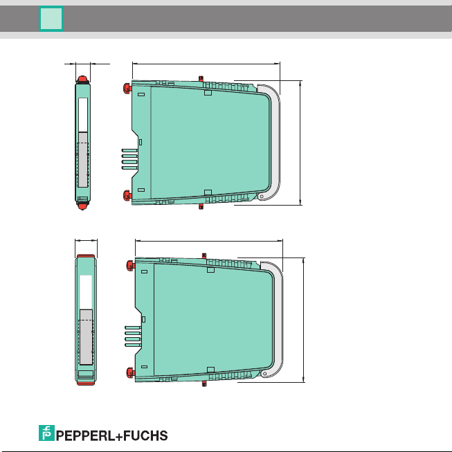
12,5 mm
(0.5")
106 mm (4.17")
128 mm (5.04")
18 mm
(0.71")
106 mm (4.17")
128 mm (5.04")
193263 09/2014
Temperature Converter HiC2081, HiD2081, HiD2082
Installation and mounting
Dimensions HiC device
Dimesnions HiD device
EN - 11
Page 12
Temperature Converter HiC2081, HiD2081, HiD2082
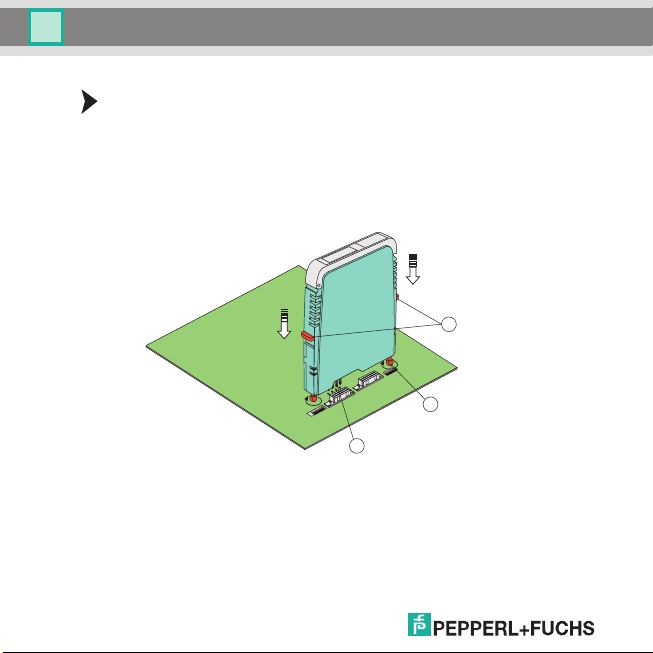
1
2
3
Installation and mounting
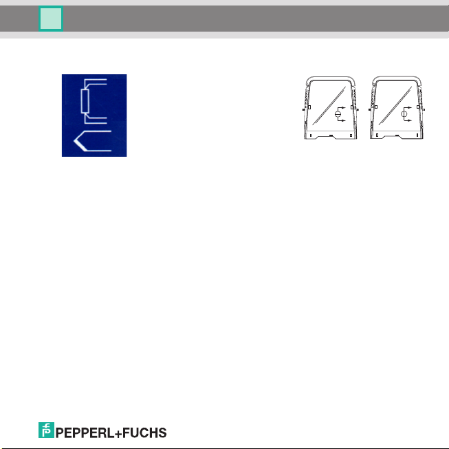
Mounting the device on the Termination Board:
• Push the Quick Lok bar (1) into the upper position.
• Center the pins (2) above the contact elements of the Termination Board. Note the
connection direction of the device.
• Center the locking pins (3) above the locking elements of the Termination Board.
• Carefully push the device into the contacts and locking elements.
• Push the red Quick Lok bar (1) down on either side of the device.
The device is mounted now.
(1) Quick Lok Bar
(2)Pins
(3)Locking pins
5. 2 Connecting the device
The device is connected by means of the terminals of the Termination Board, which permits a fast and
faultfree exchange in case of failure.
The terminals are self-opening and have a spacious connecting area for a core cross-section of up to
2.5 mm².
12 - EN
193263 09/2014
Page 13
Temperature Converter HiC2081, HiD2081, HiD2082
Installation and mounting
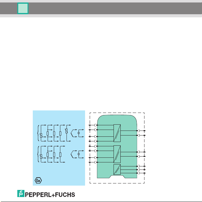
Intrinsically safe field circuits are connected to the blue Termnation Board terminals 1, 2, 5, 4
(channel I) and 7, 3, 6, 8 (channel II only HiD2082), which in keeping with DIN EN 60079-14 by means
of connecting cables can be passed into the potentially explosive area. The following sensors can be
connected (see figure):
• Potentiometer (800 ... 20 k) in 3-wire technology
•RTD (Resistance Temperature Detector) in 2-wire, 3-wire or 4-wire technology
Pt10, Pt50, Pt100, Pt500, Pt1000 according to EN 60751: 1995 or GOST6651-94
Ni 100 according to DIN 43760
Cu10, Cu50, Cu100 according to GOSTP50353-92
• Internal cold junction compensation
HiC2081: resistance thermometer for cold junction compensation H-CJC-Pt100
HiD2081, HiD2082: esistance thermometer for cold junction compensation H-CJC-SC-8,
H-CJC-SP-8
• Thermocouples
Type B, E, J, K, N, R, S, T according to IEC584-1: 1995
Type L according to DIN 43710
Type TXA, TXK, TXKH according to GOSTP8.585-2001
• Sources for voltage signals between -100 mV and +100 mV
193263 09/2014
I
II
Zone 0, 1, 2
Div. 1, 2
CJC
+-+
T
+
-
SL2
5a
1
+
1a
2
V
5
-
-
41b5b
737a
+
3a
+
V
6
-
-
83b7b
Termination Board
1a, 1b
2a, 2b
SL1
11
8a
14+-
7a
12
10a
15+-
9a
+
6b
24 V DC
FAULT
I
V
II
V
EN - 13
Page 14
Temperature Converter HiC2081, HiD2081, HiD2082
Termination Board
Zone 0, 1, 2
Div. 1, 2
I
+-+
-
V
T
V
11
14+-
+
1
2
SL2
5a
1a
-
5
41b5b
SL1
8a
7a
II
+
-
+
-
V
V
12
15+-
+
737a
3a
-
6
83b7b
10a
9a
CJC
+
-
24 V DC
FAULT
1a, 1b
2a, 2b
6b
Installation and mounting
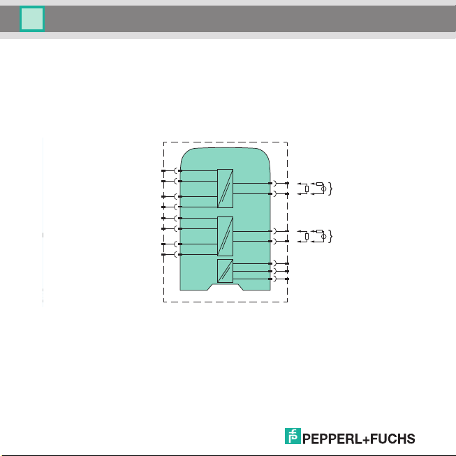
Non-intrinsically safe current circuit can be connected to the black Termination Board terminals, which
have the following function:
• Terminals 11, 14 (channel I) and 12, 15 (channel II only HiD2082): as current source, current sink or
voltage source
•Fault bus
•Power supply
• Programming socket (RS 232) for parameterisation and diagnosis using PACTware
TM
14 - EN
193263 09/2014
Page 15

0
200
400
600
800
1000
1200
16 20 25 30
U [V]
Resistor range
Temperature Converter HiC2081, HiD2081, HiD2082
Installation and mounting
If a current output is operated as a sink, the voltage of the terminals has to be between 5 V and 30 V.
An additional resistance is required only, if the voltage is over 16.5 V. The resistance has to be
between (U - 16.5 V)/0.0215 A and (U - 5 V) / 0.0215 A (see diagram).
Example: U = 24 V
(24 V - 16.5 V) / 0.0215 A = 350
(24V - 5V) / 0.0215A = 880
If a current output operated as a source, the load resistance has to be between 0 and 550 .
For more information on connections (on terminal assignment and current supply, for example), please
refer to our website at www.pepperl-fuchs.com (entry in product search: HiC2081, HiD2081 or
HiD2082).
193263 09/2014
EN - 15
Page 16
Temperature Converter HiC2081, HiD2081, HiD2082
PWR
CH 1CH 2
FAULTFAULT
HiD
2082
2 ch
Temperature
Converter
Serial
Config.
Installation and mounting
5.3 Operating and display elements
The following operating and display elements are located on the front
side of the device:
• Red LED CH1 FAULT (channel I) to display
a lead fault on input 1
(terminals 1, 2, 4, 5, flashing red)
of the simulation mode (flashing red)
a device failure (continuously red)
• Red LED CH2 FAULT (channel II only HiD2082) to display
a lead fault on input 2
(terminals 3, 6, 7, 8, flashing red)
of the simulation mode (flashing red)
a device failure (continuously red)
• green LED PWR ON, to indicate the presence of the supply voltage
• serial RS 232 interface for connection to a PC for programming and
diagnosis of the device using PACTware
TM
193263 09/2014
16 - EN
Page 17

Temperature Converter HiC2081, HiD2081, HiD2082
1
Installation and mounting
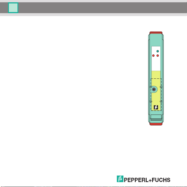
5.4 Marking
It is possible to mark the device, the signals and the device function of each individual device. For this
purpose, please use the labels offered by Pepperl+Fuchs.
Marking the device:
• Open the transparent housing cover.
• Push the label into the receptacle (1).
• Close the housing cover.
(1) Position the label receptacle
193263 09/2014
EN - 17
Page 18

Temperature Converter HiC2081, HiD2081, HiD2082
1234 5678
ON
ON OFF OFF OFF ON OFF OFF OFF
OFF ON OFF ON OFF ON OFF ON
OFF OFF ON OFF OFF OFF ON OFF
Ch.1
SW
SOURCE 4-20 mA
SW
1
CH 1 CH2
SOURCE 1-5 Volt
SINK 4-20 mA
SW2SW3SW4SW5SW6SW7SW
8
Ch.2
CAUTION
Refer to the Instruction
Manual to install and
operate the unit
OUTPUT
CONFIGURATION
2
1
Operation
6Operation
6.1 Configuration on the device
The DIP switches on the side of the device are used to set the output type for output 1 and output 2. The
two outputs can be configured differently. The output type can be selected as
• current source 4 ... 20 mA,
• current sink 4 ... 20 mA,
• or voltage source 1 V ... 5 V.
Configuring the device:
• Dismount the device (see section 9.1).
• Select the output type for output 1 and 2 (only HiD2082) from the table (1).
• Use the DIP switches (2) to set the output type for output 1 and output 2
(only HiD2082).
• Mount the device (see section 5.1).
The device is configured.
18 - EN
193263 09/2014
Page 19

Temperature Converter HiC2081, HiD2081, HiD2082
Operation
6.2 Configuration using a PC operating program
6.2.1 Installing the software components
In ord er to be abl e to config ure the dev ice by means of a PC ope rating pro gram, the f ollowing so ftware
components are required:
1. Microsoft® .NET Framework 1.1 or later
2. PACTwareTM 2.4 (Process Automation Configuration Tool) or later.
PACTwareTM is used according to FDT Specification 1.2 (Field Device Tool Specification) as a
framework program for the DTM (Device Type Manager), which is supplied by manufacturers of field
devices as configuration software.
3. DTM Collection Conventional Interface Technology. The DTM Collection comprises all device and
communication DTM required to parameterise devices of conventional interface technique.
The DTM are used to establish the communication with field devices using protocols, such as the
HART or PROFIBUS protocol.
The software components are rendered available on CD or on the Internet at www.pepperl-fuchs.com
in the product selector under Software > PACTware.
For the latest software component, please access the product selector for
Software > PACTware.
Installing the software components:
The installation of the software components is described in the "PACTwareTM Installation
Instructions" manual. Please observe the sequence of the installation steps and the
instructions in the installation instructions.
193263 09/2014
• Install Microsoft® .NET Framework.
•Install PACTware
•Use the DTM Collection Conventional Interface Technology to install the
communication DTM of your device.
TM
.
EN - 19
Page 20

Temperature Converter HiC2081, HiD2081, HiD2082
Operation
The cross-device properties of the software are described in the "PACTwareTM Process Automation
Configuration Tool" manual. For the free manual written in several languages, please access our
website at www.pepperl-fuchs.com under Software > PACTware.
Below please find the device-specific settings for temperature converter only.
6.2.2 Connecting the device
Connect the PC to the device
• Mount the device on the termination board (see section 5.1).
• Connect the device to the power supply.
• Use the adapter cable K-ADP-USB to connect the PC
to the device. This cable can be ordered as an
accessory.
• Insert the cable jack into the RS 232 interface on the front of the device and to a free
USB interface on the PC.
• Start the PACTwareTM as described in the "PACTwareTM Process Automation
Configuration Tool" manual.
193263 09/2014
20 - EN
Page 21

Temperature Converter HiC2081, HiD2081, HiD2082
Operation
6.2.3 Adjustment of the communication DTM
In a PACTwareTM project the temperature converter can be addressed by communication DTM P2P
RS232 FDT only. Please refer to the "PACTwareTM Process Automation Configuration Tool" manual to
read how to create and edit a project.
If such a driver is not available in your project yet, use the device catalog to add it to the project (see
"PACTwareTM Process Automation Configuration Tool" manual).
The only parameters of the communication DTM are the PC interfaces used and the number of repeat
attempts.
Setting the parameters
• Use the mouse to double-click on communication DTM P2P RS232 FDT in the project
window.
The Parameter window is opened.
• Select the requested communication port from the list of communication ports.
• Select the number of attempts from the list of repeat attempts.
Here the number of attempts is selected which the communication DTM carries out to
establish a connection to the connected device.
•Close the Parameter window using the button .
193263 09/2014
EN - 21
Page 22

Temperature Converter HiC2081, HiD2081, HiD2082
Operation
In order to add a device to a project, please chose communication DTM P2P RS232 FDT of the project.
Add the device to the device catalog. For more details on these working steps, please refer to the
"PACTwareTM Process Automation Configuration Tool" manual.
The description in the following chapters proceeds on the assumption that a device has been chosen
in the project.
The following submenus can be run in the Device Menu:
Device > Connect
> Disconnect
> Load from device
>Store to device
> Parameter (section 6.3)
> Measured value (section 6.2.4)
> Simulation (section 6.2.5)
> Diagnostics (section 6.2.6)
> Additional functions > Service (section 6.2.7)
Starting and stopping communication
• Start the communication between PACTwareTM and the device by running
Device > Connect.
• Stop the communication between PACTwareTM and the device by running
Device > Disconnect.
193263 09/2014
22 - EN
Page 23

Temperature Converter HiC2081, HiD2081, HiD2082
Operation
6.2.4 Measured value
The Measured value window displays the current values measured for the inputs and the current
output values.
Call the Measured value window.
• Call the Measured value window in Device > Measured value.
•Close the Measured value window using the button .
The Measured value window displays the following information on the outputs of the device:
• Measured values at the inputs in the selected unit as a bar diagram and numerically.
• Values of the analog outputs in the selected unit as a bar diagram and numerically.
193263 09/2014
EN - 23
Page 24

Temperature Converter HiC2081, HiD2081, HiD2082
Operation
6.2.5 Simulation
Simulation operation is activated or deactivated in the Simulation window.
Call the Simulation window.
• Call the Simulation window in Device > Simulation.
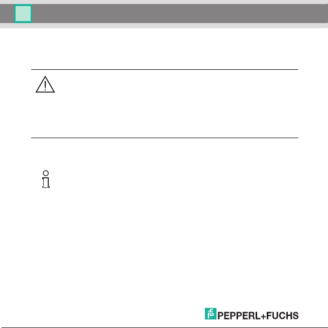
Warning!
The simulation operation may disturb or damage the device and the plant.
The simulation interrupts the normal function of the device! In case of non-observation, the
safety and function of the device as well as other devices or plants are not ensured.
• Start the simulation only, if you are sure that no hazardous condition will occur in the
plant.
193263 09/2014
24 - EN
Page 25

193263 09/2014
Temperature Converter HiC2081, HiD2081, HiD2082
Operation
Activating and deactivating simulation:
• Activate simulation with Active.
• Change the output current and/or output voltage data for test purposes.
• Press the Enter button to permit the numerical input to become effective.
• Deactivate simulation with Active. The device will resume its normal function
immediately again.
• An interruption of the power supply will also shutdown the simulation.
•Close the Simulation window by clicking on the button . The device will operate in
simulation mode until simulation is deactivated by Active.
EN - 25
Page 26

Temperature Converter HiC2081, HiD2081, HiD2082
Operation
6.2.6 Diagnostics
The Diagnostics window displays the device status as well as the status of input 1 and 2
(only HiD2082).
Call the Diagnostics window.
• Call the Diagnostics window in Device > Diagnostics.
•Close the Diagnostics window using the button .
If a diagnosis is available, it will be marked in red. The Diagnostics window contains the following
information:
193263 09/2014
26 - EN
Page 27

Temperature Converter HiC2081, HiD2081, HiD2082
Operation
Explanation:
• Memory Error: Error in the memory of the device. If this error has been caused by a wrong data
transmission, it can be remedied by accessing Device > Additional functions > Service
(see section 6.2.7). Otherwise please contact Pepperl+Fuchs.
• Internal Error: Please contact Pepperl+Fuchs.
• Redundancy error (only HiD2082): Only if Redundancy Active has been selected (page 35)
in case of a lead fault on both inputs (see above).
• Device In Simulation: see section 6.2.5
• Under Voltage Lockout: The supply voltage is too low for a correct function of the outputs. The
output render 0 mA or 0 V, irrespective of which parasitic current/which interference voltage has
been selected.
• Redundancy Deviation Error (only HiD2082): This error will be displayed only, if Redundancy
Active has been selected (page 35) for the case that the maximum deviation set is exceeded.
• Sensor Breakage: see page 32
• Sensor Short Circuit: only for sensor type RTD, see page 32
• Overrange, Underrange: The measured value is outside of the maximum measuring range of the
selected sensor (see section 6.3.4 and section 7.1 or 7.2).
• CJC Error: This error will be displayed, if the cold junction compensation has been selected
(see page 33) and a breakage or short-circuit has occurred with the H-CJC-* resistance
thermometer.
• Input 1: terminals 1, 2, 4, 5
Input 2 (only HiD2082): terminals 3, 6, 7, 8
193263 09/2014
EN - 27
Page 28

Temperature Converter HiC2081, HiD2081, HiD2082
Operation
6.2.7 Service
The device can be reset to the factory settings in the Service window. In section 10 lists all preset
parameters.
Call the Service window.
• Call the Service window by accessing the Device > Additional functions > Service.
•Set the device to Factory Reset and load.
•Close the Service window using the button .
193263 09/2014
28 - EN
Page 29

Temperature Converter HiC2081, HiD2081, HiD2082
Operation
6.3 Defining the device data
Define all device parameters in the Parameter window.
Warning!
Faults or damage may occur due to modifications of the device functions.
In case of non-observation, the safety and function of the device as well as other devices or
plants are not ensured.
• Before transmitting new data, please make sure that no danger is caused for the device
and the plant by these new data.
Call the Parameter window.
• Call the Parameter window by accessing Device > Parameter open
(see "PACTwareTM Process Automation Configuration Tool" manual).
The Parameter window contains dialog windows, which can be called via the structure in the left part
of the window. These dialog windows are described in the following chapters.
Parameter > Information (section 6.3.1)
> Description (section 6.3.2)
> Input (section 6.3.3) > Input 1
> Input 2 (only HiD2082)
> Output (section 6.3.4) > Analog Output 1
193263 09/2014
>Input Extra
> Analog Output 2 (only HiD2082)
EN - 29
Page 30

Temperature Converter HiC2081, HiD2081, HiD2082
Operation
6.3.1 Information
The device information is rendered in the Information dialog window.
Call the information dialog window.
• Call the Parameter window in Device > Parameter.
• In the directory tree select the Information dialog window.
The data on the device, the serial number, the firmware version as well as the hardware version
are displayed only and can not be modified. The device data can be read out from the device.
Reading out the device data.
• Read the device data out by accessing Device > Load from device.
Setting the supply frequency
• Use Supply Frequency to set the frequency of your network (50 Hz or 60 Hz).
In this way the best possible suppression of influences of this supply frequency on the
device is achieved.
193263 09/2014
30 - EN
Page 31

Temperature Converter HiC2081, HiD2081, HiD2082
Operation
6.3.2 Description
Use the Description dialog window to enter free descriptions of the inputs.
Call the Description dialog window.
• Call the Parameter window in Device > Parameter.
• In the directory tree select the Description dialog window.
Enter the description.
• Enter the data in the description fields.
These data can be defined and edited as you require.
193263 09/2014
EN - 31
Page 32

Temperature Converter HiC2081, HiD2081, HiD2082
Operation
6.3.3 Input
Use the Input dialog window to enter the input parameter.
Call the Input dialog window.
• Call the Parameter window in Device > Parameter.
• In the directory tree select the Input dialog window.
Three additional dialog windows are available in the Input dialog window: Input 1, Inp ut 2
(only HiD2082) and Input Extra (only HiD2082).
Input 1 and Input 2
Use the Input 1 dialog window to set the parameters for the input on the terminals 1, 2, 4, 5. Use the
Input 2 (only HiD2082) dialog window to set the parameters for the input on the terminals 3, 6, 7, 8
(see section 5. 2).
The Input 1 and Input 2 (only HiD2082) dialog windows are identical and a described together here.
193263 09/2014
32 - EN
Page 33

Temperature Converter HiC2081, HiD2081, HiD2082
Operation
Enter parameters.
•Use the Input dialog window to select Input 1 or Input 2 (only HiD2082) dialog
window.
• Set the parameters for the selected input.
The following parameters can be set:
• Sensor (see section 5. 2):
RTD (Resistance Temperature Detector): Pt100 etc.
Thermocouple: TXK etc.
Potentiometer
Voltage
• Connection Mode (for RTD only, see section 5. 2):
2-wire
3-wire
4-wire
• Unit:
for resistance temperature detectors and thermocouples: °F, K or °C
for potentiometers: fixed ratio
for voltage (sources): fixed mV
The unit selected at this point is used for all corresponding settings and displays in
PACTwareTM.
• Cold Junction Compensation (for thermocouples only):
Ext. Ref. Temp. (external reference temperature)
Internal (resistance thermometer H-CJC-*)
If Ext. Ref. Temp. has been selected, the external reference temperature can be entered (value
range: -100 °C to 320 °C)
The devices use a specific resistance thermometer for internal cold junction compensation
(see page 13).
193263 09/2014
EN - 33
Page 34

Temperature Converter HiC2081, HiD2081, HiD2082
Operation
• Lead Resistance: In case of 2-wire connection of an RTD, the lead resistor of the feed to the sensor
can be entered.
• 2-Wire Calibration: In case of 2-wire connection of an RTD, the lead resistor can be synchronised
here. For this purpose, the sensor has to be short-circuited.
• Detect Sensor Breakage (for all types of sensors)
• Detect Sensor Short Circuit (for resistance temperature detector only)
Activating and deactivating the sensor monitoring.
• Activate the monitoring system with Active.
• Deactivate the monitoring system with Active.
• Rate (for resistance temperature detectors only)
Slow
Standard
In c ase of the Standard measuring rate, the accuracy values are retained w hich are rendered in the
data sheet. In case of the Slow measuring rate, the suppression of 50 Hz and 60 Hz is improved.
• Firmware Version: The firmware version of the device can be selected here. Depending on the
firmware version, some options and functions may differ. If the firmware version is not known, the
firmware version may be read out from the device and can then be entered in this field.
Reading out the device data.
• Read the device data out by accessing Device > Load from device.
193263 09/2014
34 - EN
Page 35

Temperature Converter HiC2081, HiD2081, HiD2082
Operation
Input Extra (only HiD2082)
The Input Extra dialog window is used to activate or deactivate the redundancy.
Activating and deactivating redundancy, entering the maximum deviation.
•Use the Input dialog window to select the Input Extra dialog window.
• Activate redundancy with Active.
• Deactivate redundancy with Active.
• Enter a value for Maximum Deviation (see page 36).
193263 09/2014
EN - 35
Page 36

Temperature Converter HiC2081, HiD2081, HiD2082
Operation
The device will react as follows:
• If the Maximum Deviation between the measured values on input 1 (terminals 1, 2, 4, 5) and input 2
(terminals 3, 6, 7, 8, only HiD2082) is exceeded,
the Diagnostics window (see section 6.2.6) displays the error message for Redundancy
Deviation Error.
an error is released by the fault bus.
both outputs process the measured value on input 1 (terminals 1, 2, 4, 5, see section 5. 2).
the output does not show any failure information (fault current/fault voltage).
• If a lead fault (page 32) is recognised on one of the two inputs,
the corresponding error message is displayed in the Diagnostics window (see section 6.2.6).
an error is released by the fault bus.
the two output process the measured value of the input which is not disturbed.
the output do not release any parasitic current/no interference voltage.
• If a lead fault (page 32) is recognised on both inputs,
the Redundancy Error is displayed in the Diagnostics window (see section 6.2.6) in addition
to the corresponding error message.
an error is released by the fault bus.
the outputs display the selected behaviour for faults (see section 6.3.4 and section 7.1 or
section 7.2).
193263 09/2014
36 - EN
Page 37

Temperature Converter HiC2081, HiD2081, HiD2082
Operation
6.3.4 Output
Use the Output dialog window to enter the output parameter.
Call the output dialog window.
• Call the Parameter window in Device > Parameter.
• In the directory tree select the Output dialog window.
Two additional dialog windows are available in the Output dialog window: Analog Output 1 and
Analog Output 2 (only HiD2082).
Analog Output 1 and Analog Output 2 (only HiD2082)
Use the Analog Output 1 dialog window to set the parameters for the output on the terminals 11 and
14. Use the Analog Output 2 dialog window to set the parameters for the output on the terminals 12
and 15 (see section 5. 2).
The Analog Output 1 and Analog Output 2 dialog windows are identical and a described together
here.
193263 09/2014
EN - 37
Page 38

Temperature Converter HiC2081, HiD2081, HiD2082
Operation
Enter parameters.
•Use the Output dialog window to Analog Output 1 or Analog Output 2
(only HiD2082) dialog window.
• Set the parameters for the selected output.
The following parameters can be set:
• Assigned Input:
Input 1: Input at terminals 1, 2, 4, 5
Input 2 (only HiD2082): Input at terminals 3, 6, 7, 8, see section 5. 2
• Characteristic, if the Current Output has been selected for the output type.
4 mA ... 20 mA unlimited
4 mA ... 20 mA (NE 43)
4 mA ... 20 mA limited
0 mA ... 20 mA
For the behaviour of the current output in various settings, please refer to see section 6.4.
• Characteristic, if the Voltage Output has been selected for the output type.
1V...5V unlimited
1 V ... 5 V (NE 43)
1V...5V limited
0V...5V
For the behaviour of the voltage output in various settings, please refer to see section 6.5.
The actual selection as to whether a current or voltage signal is released, is determined by
the DIP switches on the device itself (see section 6.1). In communication DTM, the setting
has to be made manual so that the display corresponds to the real device setting.
193263 09/2014
38 - EN
Page 39

Temperature Converter HiC2081, HiD2081, HiD2082
Operation
• Start Value of the measuring range
The minimum value possible is displayed corresponding to the selected sensor. The start value can
also be accepted by means of the Online Adjustment Start Value button.
• End Value of the measuring range
The maximum value possible is displayed corresponding to the selected sensor. The end value c an
also be accepted by means of the Online Adjustment End Value button.
• Error Indication: (section 7.1 or 7.2)
Upscale
Downscale
Hold
Upscale/downscale (to be used for resistance temperature detectors only)
• Output Invert: see section 6.4 and section 6.5
Activating and deactivating the characteristic.
• Activate the inverted output with Active.
• Deactivate the inverted output with Active.
193263 09/2014
EN - 39
Page 40

Temperature Converter HiC2081, HiD2081, HiD2082
0
-25 0
Start value
100
End value
% Meas.
range
≈ 112.5
4.0
20.0
≈ 22
mA
Operation
6.4 Behaviour of the current output
The linear behaviour outside of the measuring range described in the following chapter occurs only, if
the current values correspond to the temperature values which are between the minimum and the
maximum value of the sensor selected. If this is not the case, the output current skips to the minimum
or maximum value rendered. The Diagnostics window (see section 6.2.6) is used to show the
message on the Overrange or Underrange.
If Output Invert is selected, the start value and the end value are replaced by each other.
6.4.1 Setting 4 mA ... 20 mA unlimited
At this setting, the start value of the measurement range is converted to 4 mA and the end value to
20 mA. Intermediate values are converted proportionately.
If the value falls below the start value, the output current decreases linearly to a minimum of 0 mA
(-25 % of the measurement range). Further decreases cannot be evaluated (output 0 mA). If the value
exceeds the end value, the output current increases linearly to a maximum of 22 mA (approx. 112.5 %
of the measurement range). Further increases cannot be evaluated (output approx. 22 mA).
40 - EN
193263 09/2014
Page 41

Temperature Converter HiC2081, HiD2081, HiD2082
4.0
3.8
0
20.0
20.5
-1.25 0
Start value
100
End value
% Meas.
range
≈ 103
mA
4.0
0
20.0
0
Start value
100
End value
% Meas.
range
mA
Operation
6.4.2 Setting 4 mA ... 20 mA (NE 43)
At this setting, the start value of the measurement range is converted to 4 mA and the end value to
20 mA. Intermediate values are converted proportionately.
If the value falls below the start value, the output current decreases linearly to a minimum of 3.8 mA (-
1.25 % of the measuremen t range). Further decreases cannot be evaluated (output 3.8 mA). If the value
exceeds the end value, the output current increases linearly to a maximum of 20.5 mA (approx. 103 %
of the measurement range). Further increases cannot be evaluated (output 20.5 mA).
6.4.3 Setting 4 mA ... 20 mA limited
At this setting, the start value of the measurement range is converted to 4 mA and the end value to
20 mA. Intermediate values are converted proportionately.
Values below the start value cannot be evaluated (output 4 mA). Values above the end value cannot be
evaluated either (output 20 mA).
193263 09/2014
EN - 41
Page 42

Temperature Converter HiC2081, HiD2081, HiD2082
0
20.0
20.5
0
Start value
100
End value
% Meas.
range
102.5
mA
Operation
6.4.4 Setting 0 mA ... 20 mA
At this setting, the start value of the measurement range is converted to 0 mA and the end value to
20 mA. Intermediate values are converted proportionately.
Values less than the start value cannot be evaluated (output 0 mA). If the value exceeds the end value,
the output current increases linearly to a maximum of 20.5 mA (102.5 % of the measuring range).
Further increases cannot be evaluated (output 20.5 mA).
42 - EN
193263 09/2014
Page 43

Temperature Converter HiC2081, HiD2081, HiD2082
1.0
0
5.0
≈ 5.5
-25 0
Start value
100
End value
% Meas.
range
≈ 112.5
V
Operation
6.5 Behaviour of the voltage output
The linear behaviour outside of the measuring range described in the following chapter occurs only, if
the voltage values correspond to the temperature values which are between the minimum and the
maximum value of the sensor selected. If this is not the case, the output voltage skips to the minimum
or maximum value rendered. The Diagnostics window (see section 6.2.6) is used to show the
message on the Overrange or Underrange.
If Output Invert is selected, the start value and the end value are replaced by each other.
6.5.1 Setting 1 V ... 5 V unlimited
At this setting, the start value of the measurement range is converted to 1 V and the end value to 5 V.
Intermediate values are converted proportionately.
If the value falls below the start value, the output voltage decreases linearly to a minimum of 0 V
(-25 % of the measurement range). Further decreases cannot be evaluated (output 0 V). If the value
exceeds the end value, the output voltage increases linearly to a maximum of 5.5 V
(approx. 112.5 % of the measurement range). Further increases cannot be evaluated (output approx.
5.5 V).
193263 09/2014
EN - 43
Page 44

Temperature Converter HiC2081, HiD2081, HiD2082
-1.25 0
Start value
100
End value
% Meas.
range
≈ 103
V
1.0
0.95
0
5.0
5.125
0
Start value
100
End value
% Meas.
range
1.0
0
5.0
V
Operation
6.5.2 Setting 1 V ... 5 V (NE 43)
At this setting, the start value of the measurement range is converted to 1 V and the end value to 5 V.
Intermediate values are converted proportionately.
If the value falls below the start value, the output voltage decreases linearly to a minimum of 0.95 V
(-1.25 % of the measurement range). Further decreases cannot be evaluated (output 0.95 V). If the
value exceeds the end value, the output voltage increases linearly to a maximum of 5.125 V
(approx. 103 % of the measurement range). Further increases cannot be evaluated (output 5.125 V).
6.5.3 Setting 1 V ... 5 V limited
At this setting, the start value of the measurement range is converted to 1 V and the end value to 5 V.
Intermediate values are converted proportionately.
Values below the start value cannot be evaluated (output 1 V). Values above the end value cannot be
evaluated either (output 5 V).
44 - EN
193263 09/2014
Page 45

6.5.4 Setting 0 V ... 5 V
0
0
Start value
100
End value
% Meas.
range
102.5
V
0
5.0
5.125
193263 09/2014
Temperature Converter HiC2081, HiD2081, HiD2082
Operation
At this setting, the start value of the measurement range is converted to 0 V and the end value to 5 V.
Intermediate values are converted proportionately.
Values below the start value cannot be evaluated (output 0 V). If the value exceeds the end value, the
output voltage increases linearly to a maximum of 5.125 V (approx. 102.5 % of the measurement
range). Further increases cannot be evaluated (output 5.125 V).
EN - 45
Page 46

Temperature Converter HiC2081, HiD2081, HiD2082
Trouble shooting
7Trouble shooting
7.1 Fault current
The following table shows the values of the current output during a fault, depending on the settings. For
information on the behaviour of the current output if Redundancy Active has been selected, refer to
page 36.
Setting Characteristic
Upscale approx. 22 mA
Downscale 0 mA
Hold last measured value before the fault
Upscale/
downscale
sensible only
for RTD
4 mA ... 20 mA
unlimited
(cannot be distinguished
from value exceeding end
value)
(cannot be distinguished
from value below start
value)
approx. 22 mA
in the case of lead short-
circuit
(cannot be distinguished
from value exceeding end
value)
0 mA
in the case of lead
breakage
(cannot be distinguished
from value below start
value)
Characteristics
4 mA ... 20 mA (NE 43)
4 mA ... 20 mA limited
approx. 21.5 mA approx. 21.5 mA
2.0 mA 0 mA
approx. 21.5 mA
in the case of
lead short-circuit
2.0 mA
in the case of
lead breakage
Characteristic
0mA...20mA
(cannot be distinguished
from measurement of the
start value)
approx. 21.5 mA
in the case of lead short-
in the case of lead
(cannot be distinguished
from measurement of the
start value)
circuit
0 mA
breakage
193263 09/2014
46 - EN
Page 47

Temperature Converter HiC2081, HiD2081, HiD2082
Trouble shooting
7.2 Fault voltage
The following table shows the values of the voltage output during a fault, depending on the settings. For
information on the behaviour of the voltage output if Redundancy Active has been selected, refer to
page 36.
Setting Characteristic
Upscale approx. 5.5 V
Downscale 0 V
Hold last measured value before the fault
Upscale/
downscale
sensible only for
RTD
193263 09/2014
1 V ... 5 V unlimited
(cannot be distinguished
from value exceeding end
value)
(cannot be distinguished
from value below start
value)
approx. 5.5 V
in the case of lead short-
circuit
(cannot be distinguished
from value exceeding end
value)
0 V
in the case of lead
breakage
(cannot be distinguished
from value below start
value)
Characteristics
1V...5V(NE43)
1V...5V limited
approx. 5.375 V approx. 5.375 V
0.5 V 0 V
approx. 5.375 V
in the case of
lead short-circuit
0.5 V
in the case of
lead breakage
Characteristic
0V...5V
(cannot be distinguished
from measurement of the
start value)
approx. 5.375 V
in the case of lead short-
circuit
0 V
in the case of lead
breakage
(cannot be distinguished
from measurement of the
start value)
EN - 47
Page 48

Temperature Converter HiC2081, HiD2081, HiD2082
1
Maintenance and repair
8 Maintenance and repair
The device is maintenance-free. If the device is defective,
• dismount the device (see section 9.1), and
• return it to Pepperl+Fuchs for repair or
•replace the device.
Own interventions and modifications are potentially hazardous, and any guarantee and manufacturer's
liability shall become void.
9 Dismounting, storage and disposal
9.1 Dismounting
• Pull the red Quick Lok Bar (1) up on either side of the device (see figure).
• Carefully pull the device out of the contact receptacle.
(1) Quick Lok Bar
193263 09/2014
48 - EN
Page 49

Temperature Converter HiC2081, HiD2081, HiD2082
Dismounting, storage and disposal
9.2 Storage
Pack the device for storage to protect it against impact and soiling. The original packaging offers perfect
protection for the device. Store the device in a dry environment protecting it against humidity and
aggressive media. The permissible storage temperature rang es from -40 °C to 90 °C (-40 °F to 194 °F).
9.3 Disposal
Separate the device components according to their materials. Recycle any recyclable components.
Caution!
The material of the device components may be a hazard to the environment.
Electronic waste is hazardous waste.
• Please observe the legal and local regulations applicable at the point of disposal of
clapped-out devices.
193263 09/2014
EN - 49
Page 50

Temperature Converter HiC2081, HiD2081, HiD2082
Factory settings
10 Factory settings
The device is supplied with preset factory parameters. The following table lists all parameters.
Parameter Factory settings Own settings
Supply Frequency 50 Hz
Input 1 2 (only HiD2082) 1 2 (only HiD2082)
Sensor Pt100 Pt100
Connection Mo de 3-wire 3-wi re
Unit °C °C
Cold Junction
Compensation
Ext. Ref. Temp. 25 °C 25 °C
Lead Resistance 0.0 0 0.00
Sensor Breakage Active Active
Sensor Short Circuit Active Active
Rate Standard Standard
Firmware Version Version 1.35 Version 1.35
Input Extra
Redundancy Deactivated
Maximum Deviation 1 °C
Output 1 2 (only HiD2082) 1 2 (only HiD2082)
Assigned Input 1 2 (only HiD2082)
Characteristic 4 ... 20 mA, NE 43 4 ... 20 mA, NE 43
Star t Val ue 0 ° C 0 °C
End Value 200 °C 200 °C
Error Indication Downscale Downscale
Output Invert Deactivated Deactivated
Output Type Current Output Current Output
Internal (H-CJC-*) Internal (H-CJC-*)
193263 09/2014
50 - EN
Page 51

193263 09/2014
Temperature Converter HiC2081, HiD2081, HiD2082
Notes
EN - 51
Page 52

PROCESS AUTOMATION –
PROTECTING YOUR PROCESS
Worldwide Headquarters
Pepperl+Fuchs GmbH
68307 Mannheim · Germany
Tel. +49 621 776-0
E-Mail: info@de.pepperl-fuchs.com
For the Pepperl+Fuchs representative
closest to you check www.pepperl-fuchs.com/contact
www.pepperl-fuchs.com
Subject to modifications
Copyright PEPPERL+FUCHS
· Printed in Germany
193263 DOCT-0963B
09/2014
 Loading...