

Page 1
PROFIBUS POWER HUB
SEGMENT COUPLER
PROCESS AUTOMATION
MANUAL
HD2-GTR-4PA
Page 2

With regard to the supply of products, the current issue of the following document is applicable:
The General Terms of Delivery for Products and Services of the Electrical Industry, as published by
"
the Central Association of the „Elektrotechnik and Elektroindustrie (ZVEI) e.V.“,
including the supplementary clause „Extended reservation of title“.
We at Pepperl+Fuchs recognise a duty to make a contribution to the future.
For this reason, this printed matter is produced on paper bleached without the use of chlorine.
Page 3

PROFIBUS POWER HUB SEGMENT COUPLER
Table of Contents
Subject to reasonable modifications due to technical advances. Copyright Pepperl+Fuchs, Printed in Germany
Pepperl+Fuchs Group • Tel.: Germany +49-621-776-0 • USA +1-330-4253555 • Singapore +65-67-799091 • Internet www.pepperl-fuchs.com
3
1 Safety .........................................................................................................6
1.1 Validity ............................................................................................6
1.2 Symbols Used .................................................................................6
1.3 System Operator and Personnel ....................................................6
1.4 Pertinent Laws, Standards, Directives, and further Documentation 6
1.5 Delivery, Transport and Storage .....................................................7
1.6 Marking ...........................................................................................7
1.7 Intended Use ..................................................................................8
1.8 Mounting and Installation ................................................................8
1.8.1 Mounting Instructions for Power Hub ..................................8
1.8.2 Mounting instructions for HD2-GT* modules ....................... 9
1.8.3 Shield/Grounding .................................................................9
1.9 Housing ...........................................................................................9
1.10 Repair and Maintenance .................................................................9
1.11 Disposal ........................................................................................10
2 Specification .............................................................................................11
2.1 Overview .......................................................................................11
2.2 Coupling ........................................................................................12
2.3 Segment Supply ...........................................................................13
2.4 System Components ....................................................................13
2.4.1 Motherboards ....................................................................13
2.4.2 Modules for Coupling, Supply and Diagnosis .................... 14
2.5 Recommended System Combinations .........................................15
2.5.1 Case 1: Fully Redundant ...................................................15
2.5.2 Case 2: Redundant Coupling ............................................15
2.5.3 Case 3: Simplex ................................................................16
2.6 Component Identity .......................................................................17
2.7 Technical Data ..............................................................................19
2.8 Dimensions ...................................................................................21
3 Installation and Commissioning ...............................................................22
3.1 Mounting and Dismounting ...........................................................22
3.2 Shield/Grounding ..........................................................................23
3.3 Connections ..................................................................................25
3.3.1 Master Connection to a Redundant PROFIBUS
Power Hub System ............................................................27
4 Installation in Hazardous Areas ...............................................................28
4.1 Installation in Zone 2 Category 3G ...............................................28
Page 4

PROFIBUS POWER HUB SEGMENT COUPLER
Table of Contents
Subject to reasonable modifications due to technical advances. Copyright Pepperl+Fuchs, Printed in Germany
Pepperl+Fuchs Group • Tel.: Germany +49-621-776-0 • USA +1-330-4253555 • Singapore +65-67-799091 • Internet www.pepperl-fuchs.com
4
5 PROFIBUS Commissioning ..................................................................... 29
5.1 Assigning a Device Address ......................................................... 29
5.2 Commissioning of Cyclic Data Exchange ..................................... 29
5.2.1 Information on the GSD Conversion ................................. 31
5.2.2 Additional Information about Watchdog time .................... 33
5.2.3 Information about I/O Cycle Time ..................................... 34
5.2.4 Additional Information on Adjusting Retry ......................... 35
5.3 DTM Software Installation and Commissioning ............................ 35
6 Operation ................................................................................................. 40
6.1 Built-In-Slave (BIS) Description .................................................... 40
6.1.1 Cyclic Data Exchange ....................................................... 40
6.1.2 Parameterization Options (Channel Assignment) ............. 40
6.1.3 Diagnostics (Slave Diagnostics) ........................................ 41
6.2 Coupled Slaves ............................................................................ 43
6.3 Acyclic Data Exchange with BIS via DTM .................................... 43
6.3.1 Brief introduction to DTM with PACT
ware
TM
as an Example .................................................................. 44
6.3.2 Overview of the DTM User Interface ................................. 46
6.3.3 Structure Diagram ............................................................. 47
6.3.4 Watchdog Time in the DTM .............................................. 48
6.3.5 PA Retry Limit Setting ....................................................... 49
6.3.6 Restart Functions, Redundancy Switchover and Firmware Update 49
6.4 Redundant Operation ................................................................... 53
6.4.1 Redundancy Behavior ....................................................... 53
6.4.2 System Environment for Redundant Operation ................ 53
6.4.3 Applications with Redundant Operation ............................ 54
7 Advanced Diagnostics with the PROFIBUS Power Hub .......................... 56
7.1 Advanced Diagnostics Infrastructure ............................................ 56
7.1.1 Advanced Diagnostics Connection via PROFIBUS DP .... 56
7.1.2 Advanced Diagnostics Connection via Diagnostic Bus ..... 58
7.2 PROFIBUS Advanced Diagnostics Integration ............................ 61
7.2.1 Advanced Diagnostic Messages in the Gateway DTM ..... 62
8 Basic Principles ....................................................................................... 63
8.1 Redundancy Concepts ................................................................. 63
8.1.1 Overview ........................................................................... 63
8.1.2 Flying Redundancy ........................................................... 63
8.1.3 System Redundancy ......................................................... 64
9 Appendix 1 / Glossary .............................................................................. 65
Page 5

PROFIBUS POWER HUB SEGMENT COUPLER
Table of Contents
Subject to reasonable modifications due to technical advances. Copyright Pepperl+Fuchs, Printed in Germany
Pepperl+Fuchs Group • Tel.: Germany +49-621-776-0 • USA +1-330-4253555 • Singapore +65-67-799091 • Internet www.pepperl-fuchs.com
5
10 Parameter Reference List ........................................................................69
10.1 General Parameters .....................................................................69
10.1.1 PA Master Parameters ......................................................69
10.1.2 PA Segment Parameters ...................................................70
10.2 Diagnostic Parameters .................................................................70
10.2.1 Device Diagnostic Parameters ..........................................70
10.2.2 PA Segment Diagnostic Parameters .................................71
10.2.3 Redundancy Partner Parameters ...................................... 72
11 Troubleshooting .......................................................................................73
11.1 Faults Indicated via LEDs .............................................................73
11.2 Faults Indicated via DTM ..............................................................75
11.3 Faults Indicated via DCS ..............................................................77
11.4 Problems with Gateway Operation ...............................................79
Page 6

PROFIBUS POWER HUB SEGMENT COUPLER
Safety
Subject to reasonable modifications due to technical advances. Copyright Pepperl+Fuchs, Printed in Germany
Pepperl+Fuchs Group • Tel.: Germany +49 621 776-0 • USA +1 330 4253555 • Singapore +65 67799091 • Internet http://www.pepperl-fuchs.com
6
Date of Issue 24.3.11
1 Safety
1.1 Validity
The chapter "Safety" is valid as operating instructions.
Specific process and instructions in this document require special pre-
cautions to guarantee the safety of personnel.
1.2 Symbols Used
1.3 System Operator and Personnel
The operator of the system is responsible in terms of planning, mounting, commissioning, operating and maintenance.
Assembly, commissioning, operation, maintenance and dismounting of
any devices may only be carried out by trained, qualified personnel who
have read and understood the instruction manual.
1.4 Pertinent Laws, Standards, Directives, and further
Documentation
Laws, standards, or directives applicable to the intended use must be
observed. In relation to explosive areas, Directive 1999/92/EC must be
observed.
This symbol indicates a warning about a possible danger.
In the event the warning is ignored, the consequences may range from
personal injury to death or from damage to equipment to destruction.
This symbol warns of a possible fault. Failure to observe the instructions
given in this warning may result in the device and any connected facilities
or systems to it develop a fault or fail completely.
This symbol brings important information to your attention.
This symbol marks an acting paragraph.
Warning
Attention
Note
Page 7

PROFIBUS POWER HUB SEGMENT COUPLER
Safety
Subject to reasonable modifications due to technical advances. Copyright Pepperl+Fuchs, Printed in Germany
Pepperl+Fuchs Group • Tel.: Germany +49 621 776-0 • USA +1 330 4253555 • Singapore +65 67799091 • Internet http://www.pepperl-fuchs.com
7
Date of Issue 24.3.11
The corresponding data sheets, the declaration of conformity, the ECtype-examination certificate and applicable certificates (see data sheet)
are an integral part of this document. You can find this information under
www.pepperl-fuchs.com.
1.5 Delivery, Transport and Storage
Check the packaging and contents for damage.
Check if you have received every item and if the items received are the
ones you ordered.
Keep the original packaging. Always store and transport the device in
the original packaging.
Always store the device in a clean, dry environment. Note the permitted
storage temperature (see data sheet).
1.6 Marking
Gateway motherboards
Gateway module
MB-FB-GT
Pepperl+Fuchs GmbH
Gateway motherboard
Declaration of Conformity
TÜV 04 ATEX 2500X
•
Ex II 3G EEx nA IIC T4
MB-FB-GTR
Pepperl+Fuchs GmbH
Redundant gateway motherboard
Declaration of Conformity
TÜV 04 ATEX 2500X
•
Ex II 3G EEx nA IIC T4
HD2-GTR-4PA
Pepperl+Fuchs GmbH
Gateway module
Declaration of Conformity
TÜV 04 ATEX 2500X
•
Ex II 3G EEx nA IIC T4
Page 8

PROFIBUS POWER HUB SEGMENT COUPLER
Safety
Subject to reasonable modifications due to technical advances. Copyright Pepperl+Fuchs, Printed in Germany
Pepperl+Fuchs Group • Tel.: Germany +49 621 776-0 • USA +1 330 4253555 • Singapore +65 67799091 • Internet http://www.pepperl-fuchs.com
8
Date of Issue 24.3.11
1.7 Intended Use
The PROFIBUS Power Hub Segment Coupler, as part of the Power Hub
System, serves as a Segment Coupler for connecting PROFIBUS PA
segments to PROFIBUS DP. Various Power Hub Power Supply solutions offer either simplex or redundant power to PROFIBUS PA segments. Power Hub Supplies for High-Power Trunk and the Fieldbus intrinsically safe concept DART are available.
The Segment Coupler ensures communication and galvanic isolation
between PROFIBUS PA and PROFIBUS DP. The Segment Coupler can
be used in all system environments in compliance with industry standard PROFIBUS DP Masters.
PROFIBUS PA is an extended version of the PROFIBUS DP that allows
for the physical transmission specifications of IEC 61158-2. Fieldbus
devices receive their electrical supply through the transmission lines.The combination of PROFIBUS Power Hub components makes it
possible to connect and supply four PROFIBUS PA segments per Gateway to the PROFIBUS DP.
The Segment Coupler may be installed in Zone 2 Category 3G hazardous areas. Types of protection are Ex nA (non-arcing) for Zone 2 Gas
Groups IIC, IIB, IIA.
The devices are only approved for appropriate and intended use. Ignoring these instructions will void any warranty and absolve the manufacturer from any liability.
The device must only be operated in the ambient temperature range
and at the relative humidity (non-condensing) specified.
1.8 Mounting and Installation
Prior to mounting, installation, and commissioning of the device you
should make yourself familiar with the device and carefully read the instruction manual.
The devices may be installed in a corrosive location acc. to ISA-S71.041985, severity level G3.
1.8.1 Mounting Instructions for Power Hub
The devices should be installed at least in an environment according
pollution degree 2.
Instructions for Zone 2
The devices may only be installed and operated in Zone 2 if they have
been mounted in an enclosure with degree of protection IP 54 acc.to
IEC/EN 60529. The enclosure must have a declaration of conformity according to 94/9/EC for at least category 3G.
Page 9

PROFIBUS POWER HUB SEGMENT COUPLER
Safety
Subject to reasonable modifications due to technical advances. Copyright Pepperl+Fuchs, Printed in Germany
Pepperl+Fuchs Group • Tel.: Germany +49 621 776-0 • USA +1 330 4253555 • Singapore +65 67799091 • Internet http://www.pepperl-fuchs.com
9
Date of Issue 24.3.11
Connection or disconnection of energized non-intrinsically-safe circuits
is only permitted in the absence of a hazardous area.
Instructions for Zone 22
The devices may only be installed and operated in zone 22 if mounted
in an enclosure for which an EC-type-examination certificate acc. 94/9/
EG for at least category 3D exists.
1.8.2 Mounting instructions for HD2-GT* modules
The modules are intended for mounting on an appropriate Fieldbus Power Hub Gateway motherboard.
1.8.3 Shield/Grounding
Take care about good earthing practice and specific earthing requirements of your installation (see chapter “Shield/Grounding” on page 23).
Observe IEC 60079-14 for requirements of potential equalization.
1.9 Housing
The device must be mounted at least in protection category IP 54 in accordance with IEC 60529/EN 60529.
If additional housings are needed for installation in hazardous areas, the
following points must be considered / evaluated:
• Degree of protection as per IEC/EN 60529
• Light resistance as per IEC/EN 60079-0
• Impact strength as per IEC/EN 60079-0
• Chemical resistance as per IEC/EN 60079-0
• Heat resistance as per IEC/EN 60079-0
• Electrostatics as per IEC/EN 60079-0
To ensure the IP degree of protection:
• All seals must be undamaged and have been correctly fitted.
• All screws of the housing / housing cover must have been tightened with the appropriate torque.
• Only cable of the appropriate size must be used in the cable
glands.
• All cable glands must have been tightened with the appropriate
torque.
• All empty cable glands must have been sealed with sealing
plugs.
1.10 Repair and Maintenance
The devices may not be repaired, changed or manipulated. If there is a
defect, the product must always be replaced with an original part.
Page 10

PROFIBUS POWER HUB SEGMENT COUPLER
Safety
Subject to reasonable modifications due to technical advances. Copyright Pepperl+Fuchs, Printed in Germany
Pepperl+Fuchs Group • Tel.: Germany +49 621 776-0 • USA +1 330 4253555 • Singapore +65 67799091 • Internet http://www.pepperl-fuchs.com
10
Date of Issue 24.3.11
1.11 Disposal
Devices, packaging material, and possibly contained batteries must be
disposed of in compliance with the applicable laws and guidelines of the
corresponding country.
Page 11
PROFIBUS POWER HUB SEGMENT COUPLER
Specification
Subject to reasonable modifications due to technical advances. Copyright Pepperl+Fuchs, Printed in Germany
Pepperl+Fuchs Group • Tel.: Germany +49 621 776-0 • USA +1 330 4253555 • Singapore +65 67799091 • Internet http://www.pepperl-fuchs.com
11
Date of Issue 24.3.11
2 Specification
2.1 Overview
The Pepperl+Fuchs PROFIBUS Power Hub System has a modular design. It offers a number of possible combinations so it can be adapted
to the specific requirements of different explosion protection concepts or
the need for increased segment availability.
Functionally, the system may be divided into two component groups:
• Coupling (described in this manual)
• Segment supply (described in the Power Hub manuals)
Modules and Motherboards are assigned to these groups as shown:
•
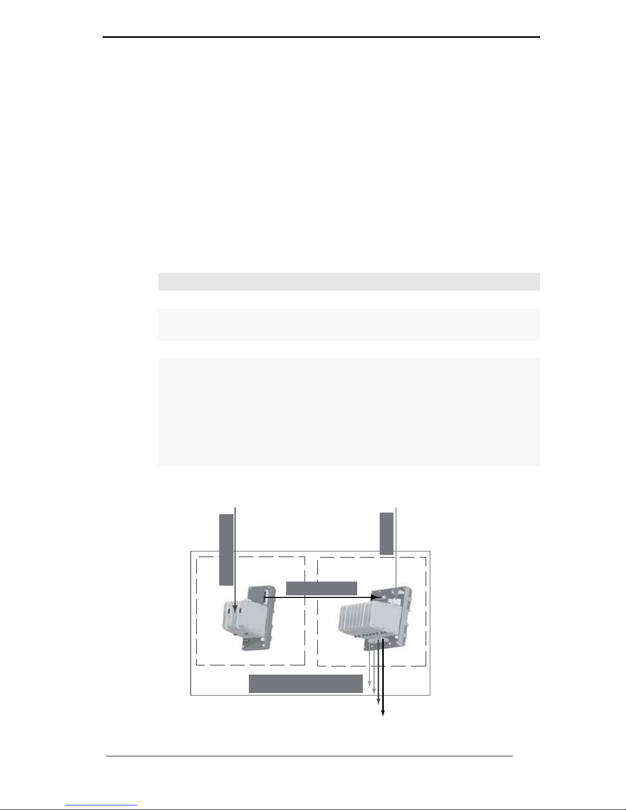
Figure 2.1: Coupling and Supply for the PROFIBUS Power Hub System
Coupling: Segment supply:
Modules:
Gateway Module HD-2-GTR-4.PA Power Hub Modules HD2-FB*
HD2-DM* Diagnostic Modules
Motherboards:
Gateway Motherboard simplex:
MB-FB-GT
Gateway Motherboard redundant:
MB-FB-GTR
Power Hub Motherboards simplex
or redundant:
MB-FB*.GEN
MBHD-FB*.GEN
DART Power Hub Motherboard
redundant:
MBHD-FB-D-4R.GEN
PROFIBUS DP
PROFIBUS PA
Energy
4 x PA-Fieldbus trunk
Coupling
Supply
Profibus Power Hub system
Page 12

PROFIBUS POWER HUB SEGMENT COUPLER
Specification
Subject to reasonable modifications due to technical advances. Copyright Pepperl+Fuchs, Printed in Germany
Pepperl+Fuchs Group • Tel.: Germany +49 621 776-0 • USA +1 330 4253555 • Singapore +65 67799091 • Internet http://www.pepperl-fuchs.com
12
Date of Issue 24.3.11
Various Power Hub power supply solutions offer either simplex or redundant power to PROFIBUS PA segments. The Power Hub consists of
a motherboard with sockets for plug-in modules.
• One power supply module per segment in simplex mode or, alternatively, two power supply modules per segment in redundant mode.
• A physical layer diagnostic module HD2-DM*.
The Power Hub feeds fieldbus segments following the High-Power
Trunk concept for explosion protection. High energy level on the trunk
line is fed to the field instruments via couplers like FieldBarriers or Segment Protectors. A dedicated version of the Power Hub (DART) supports the intrinsically safe concept for fieldbus.
A plug-in Advanced Diagnostic Module for fieldbus is available. This module monitors the physical layer online and in real time enabling detection of degradation and faults during operation. Measurement data and
alarms are transmitted to the control room thus bringing visibility to the
fieldbus physical layer, which can now be treated as active component
in Plant Asset Management systems. Operators are enabled to decide
on proactive measures to avoid unwanted situations while the plant is
running smoothly.
2.2 Coupling
Coupling involves a Gateway Motherboard and one or, in the case of
redundant coupling, two Gateway Modules.
The purpose of coupling is to adjust the physical transmission properties on the DP side (RS 485) to those of the PROFIBUS PA (in conformity with IEC 61158-2). The coupling provides a baudrate of 31.25 kbit/
s on the PA side. In addition, the coupling creates galvanic isolation between PROFIBUS DP and PROFIBUS PA. The DP/PA coupling of the
PROFIBUS Power Hub System is functionally compatible with the Pepperl+Fuchs SK 2 System, which is well established on the market.
The coupling of the PROFIBUS PA slave to the PROFIBUS DP is transparent. This means that all PA slaves appear on the DP bus and are interpreted by the Host as DP slaves. A DP address is also assigned to
the Gateway itself for diagnostic and parameterization purposes.
Although segment supply is part of the PROFIBUS Power Hub System,
it is not described in this manual (only where needed for better understanding). Please refer to the respective „Generic Power Hub“ manuals
for detailed information on segment supply.
Note
Page 13

PROFIBUS POWER HUB SEGMENT COUPLER
Specification
Subject to reasonable modifications due to technical advances. Copyright Pepperl+Fuchs, Printed in Germany
Pepperl+Fuchs Group • Tel.: Germany +49 621 776-0 • USA +1 330 4253555 • Singapore +65 67799091 • Internet http://www.pepperl-fuchs.com
13
Date of Issue 24.3.11
Cyclic data exchange can be connected redundantly to the DP line by
using the redundant Gateway Motherboard MB-FB-GTR and two
HD2-GTR-4PA Gateways.
The Gateway Module HD2-GTR-4PA supports PROFIBUS
"Flying Redundancy“ (chapter “Redundancy Concepts” on page 63) as
well as all non-redundant DP Masters.
In summary, the Gateway is responsible for the following tasks:
• Conversion of the PROFIBUS DP physical layout to that of the
PROFIBUS PA
• Adjusting the DP transmission rate to the PA transmission rate
• Galvanic isolation between PROFIBUS DP and PA
• Elementary functional diagnostics via LEDs
• Ensuring increased availability through redundant coupling of
cyclic data exchange (with redundant layout)
• Acyclic Parameterization of Gateway parameters by
FDT/DTM
• Redundancy diagnostics (with redundant layout)
2.3 Segment Supply
Power is supplied to the field devices through Power Hub Modules on a
Power Hub Motherboard (simplex: 4 Power Hub connection slots, redundant: 8 connection slots) and via bus lines to the individual segments.
PA segments can receive redundant power supply if the redundant Power Hub Motherboard is used along with two Power Hub Modules for
each segment.
In summary, the supply is responsible for the following tasks:
• Power supply of field devices: power and communication signal
• Redundant supply for high system availability
• Elementary diagnostic information via LEDs
• Advanced Physical Layer Diagnostics via the HD2-DM* Diagnostic Module and the FDT/DTM software package (see corresponding documentation).
2.4 System Components
2.4.1 Motherboards
Gateway motherboard simplex MB-FB-GT
The gateway motherboard simplex MB-FB-GT allows the connection of
the Fieldbus Power Hub motherboards MB-FB*.GEN or MBHDFB*.GEN using a standard cable. A socket will hold the DP/PA Gateway
HD2-GTR-4PA. The Built-In Slave of the HD2-GTR-4PA can be addressed using the DIP switch on the motherboard.
Page 14

PROFIBUS POWER HUB SEGMENT COUPLER
Specification
Subject to reasonable modifications due to technical advances. Copyright Pepperl+Fuchs, Printed in Germany
Pepperl+Fuchs Group • Tel.: Germany +49 621 776-0 • USA +1 330 4253555 • Singapore +65 67799091 • Internet http://www.pepperl-fuchs.com
14
Date of Issue 24.3.11
Gateway motherboard redundant MB-FB-GTR
The gateway motherboard redundant MB-FB-GTR allows the connection of the Fieldbus Power Hub motherboards MB-FB*.GEN or MBHDFB*.GEN with a standard cable. Two sockets will hold two DP/PA Gateways HD2-GTR-4PA. The Built-In Slaves of the HD2-GTR-4PA modules
can be addressed using the DIP switch on the motherboard.
Power Hub motherboard simplex MB-FB-4.GEN
The MB-FB-4.GEN allows the supply of four Fieldbus segments as well
as the direct connection of the PROFIBUS DP/PA Gateway Motherboards MB-FB-GT or MB-FB-GTR with a standard cable. Four sockets
hold the Power Modules. The modules are available for different explosion protection concepts and with various isolation levels. A further sokket holds a Diagnostic Module
Power Hub motherboards redundant MB*-4R.GEN
The MB*-4R.GEN motherboards allow the redundant supply of four
fieldbus segments as well as the direct connection of the PROFIBUS
DP/PA Gateway Motherboards MB-FB-GT or MB-FB-GTR with a standard cable. Eight sockets hold the power supply modules, two power
supply modules supplying each of the four segments redundantly. The
modules are available for different explosion protection concepts and
with various isolation levels. A further socket holds a Diagnostic Module.
DART Power Hub motherboard redundant MBHD-FB-D-4R.GEN
The MBHD-FB-D-4R.GEN motherboard allows for the redundant supply of four intrinsically safe Ex ib fieldbus segments as well as the direct
connection of the PROFIBUS DP/PA Gateway Motherboards MB-FBGT or MB-FB-GTR with a standard cable. Eight sockets hold the power
supply modules, two power supply modules supplying each of the four
segments redundantly. A further socket holds a Diagnostic Module.
2.4.2 Modules for Coupling, Supply and Diagnosis
Gateway module HD2-GTR-4.PA
The Gateway module provides the connection of four PROFIBUS PA
segments to a PROFIBUS DP. In conjunction with Fieldbus Power Modules, PA segments are supplied directly via Fieldbus lines. Coupling is
transparent, so each PA device is addressed and configured as a PROFIBUS DP device.
The HD2-GTR-4PA module includes four full-featured PA masters, who
perform data exchange time independently.
The FDT/DTM based PC software package allows the parameterization
of the Gateway and offers several status and diagnostic functionalities.
Used in connection with the corresponding motherboard, two Gateways
Page 15

PROFIBUS POWER HUB SEGMENT COUPLER
Specification
Subject to reasonable modifications due to technical advances. Copyright Pepperl+Fuchs, Printed in Germany
Pepperl+Fuchs Group • Tel.: Germany +49 621 776-0 • USA +1 330 4253555 • Singapore +65 67799091 • Internet http://www.pepperl-fuchs.com
15
Date of Issue 24.3.11
provide redundant coupling. The HD2-GTR-4PA supports PROFIBUS
„Flying Redundancy“ as well as all non-redundant masters.
Power modules HD2-FB*
Power Modules supply electrical power to segments. They couple the
supply current to the two-wire Fieldbus cable while maintaining the highest signal quality.
Diagnostic modules HD2-DM*
Diagnostic modules are divided into the Basic Diagnostic Module HD2DM-B and the Advanced Diagnostic Module HD2-DM-A. The diagnostic
modules provide various system diagnostics.
2.5 Recommended System Combinations
2.5.1 Case 1: Fully Redundant
In the fully redundant system, both coupling of PROFIBUS DP to
PROFIBUS PA and the supply of the four segments are designed redundantly. The fully redundant PROFIBUS Power Hub consists of the following components:
• Gateway motherboard MB-FB-GTR
• Power Hub motherboard MB*-4R.GEN
• 2 x HD2-GTR-4PA
• 8 x Power Modules
• 1 x Diagnostic Module
• 1 x Sub-D cable to connect motherboards
The fully redundant system offers the highest protection against individual failures or failure of all PA segments of PROFIBUS.
2.5.2 Case 2: Redundant Coupling
In this case, coupling is designed redundantly, but there is only one
supply per segment (simplex). The redundantly coupled system consists of the following components:
• Gateway motherboard MB-FB-GTR
• Power Hub motherboard MB-FB-4.GEN
• 2 x HD2-GTR-4PA
• 4 x Power Modules
• 1 x Diagnostic Module
• 1 x Sub-D cable to connect motherboards
Redundant coupling ensures communication of the four PA segments.
Failure of one segment has no effect on the other three segments.
Page 16

PROFIBUS POWER HUB SEGMENT COUPLER
Specification
Subject to reasonable modifications due to technical advances. Copyright Pepperl+Fuchs, Printed in Germany
Pepperl+Fuchs Group • Tel.: Germany +49 621 776-0 • USA +1 330 4253555 • Singapore +65 67799091 • Internet http://www.pepperl-fuchs.com
16
Date of Issue 24.3.11
2.5.3 Case 3: Simplex
In the simplex system, both the coupling of DP to PA and the supply of
the four segments are single (simplex). The simplex system consists of
the following components:
• Gateway motherboard MB-FB-GT
• Power Hub motherboard MB-FB-4.GEN
• 1 x HD2-GTR-4PA
• 4 x Power Modules
• 1 x Diagnostic Module
• 1 x Sub-D cable to connect motherboards
Combining a simplex Gateway Motherboard and a redundant Power Hub
Motherboard also makes a fourth combination possible. Pepperl+Fuchs
does not recommend using this arrangement. Since a fault in the coupling of DP to PA results in failure of all four segments together, but the
failure of a single segment does not have any effect on the remaining
segments, increased segment availability can be achieved most easily
with redundant coupling (as described in case 1 and case 2).
Note
Page 17
PROFIBUS POWER HUB SEGMENT COUPLER
Specification
Subject to reasonable modifications due to technical advances. Copyright Pepperl+Fuchs, Printed in Germany
Pepperl+Fuchs Group • Tel.: Germany +49 621 776-0 • USA +1 330 4253555 • Singapore +65 67799091 • Internet http://www.pepperl-fuchs.com
17
Date of Issue 24.3.11
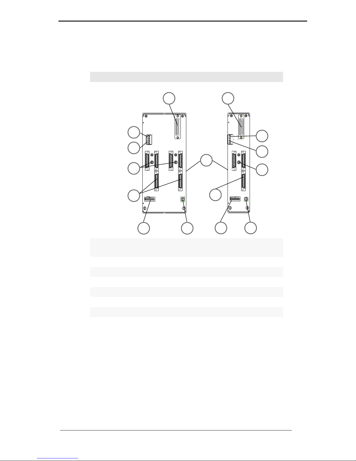
2.6 Component Identity
MB-FB-GTR MB-FB-GT
1 Sub-D connection to Power Hub mother
board
2 VFC alarm contact
3 Diagnostic bus contact
4 Slots for DP/PA Gateway Modules
5 DIP Switch for BIS address
6 Screen/ground connection clamp
7 Motherboard fastening screws
8 DIN rail slot
1
4
5
1
4
5
6
6
8
3
2
3
2
7
7
Page 18
PROFIBUS POWER HUB SEGMENT COUPLER
Specification
Subject to reasonable modifications due to technical advances. Copyright Pepperl+Fuchs, Printed in Germany
Pepperl+Fuchs Group • Tel.: Germany +49 621 776-0 • USA +1 330 4253555 • Singapore +65 67799091 • Internet http://www.pepperl-fuchs.com
18
Date of Issue 24.3.11
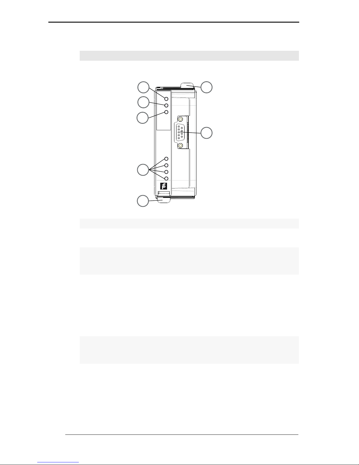
HD2-GTR-4PA
1 Quick Lok Bar
2 LED „PWR“
• Green: Device in operation
3 LED „DP/ERROR“
• Red, flashing with 2 Hz: DP error.
• Red: Hardware error
4 LED Redundancy
• Yellow: Redundant operation (this Gateway Module is the primary
device)
• Yellow, flashing with 2 Hz: Synchronisation or Redundancy not
available (this Gateway Module is the primary device)
• LED is off: simplex operation; in redundant mode, this Gateway Modul is the secondary device
5 Segment status LEDs
• LED segments 1...4. Red, flashing with 2 Hz: PA error
• Segment LED and LED „DP/ERROR“ on: MAU hardware error
6 PROFIBUS DP connection
PROFIBUS
DP/P
A
Gateway
HD2GTR4P A
Seg4
Seg3
Seg2
Seg1
PW R
DP/
ERR
Red.
1
5
1
4
6
3
2
Page 19

PROFIBUS POWER HUB SEGMENT COUPLER
Specification
Subject to reasonable modifications due to technical advances. Copyright Pepperl+Fuchs, Printed in Germany
Pepperl+Fuchs Group • Tel.: Germany +49 621 776-0 • USA +1 330 4253555 • Singapore +65 67799091 • Internet http://www.pepperl-fuchs.com
19
Date of Issue 24.3.11
2.7 Technical Data
System overview
Ambient conditions:
Ambient temperature -40..60 °C
Storage temperature -40..85 °C
Relative humidity <95% non-condensing
Shock resistance 15 g 11 ms
Vibration resistance 1 g, 58 to 150 Hz
Mechanical data:
Protection degree IP 20 acc. to EN 60529
Motherboard mounting Mounting rail, 35 mm
Conformity to standards:
Shock resistance
Vibration resistance
Fieldbus standard
EMV
DIN EN 60068-2-27
DIN EN 60068-2-6
IEC 61158
Namur NE 21
EN 61326
Installation in hazardous areas:
Approvals: Zone 2
II 3 G Ex nA II T4
Class 1
Division 2
Gas groups IIC, IIB, IIA
HD2-GTR-4PA
Supply:
Rated voltage 19.2 to 35 V DC
Rated current 160... 90 mA
Power dissipation 3W
Fieldbus interface/PROFIBUS DP:
Connection SUB-D-socket, 9-pin
Protocol PROFIBUS DP V1
Galvanic isolation:
PROFIBUS DP/CH
PROFIBUS DP/supply
All circuits/FE
Functional isolation per IEC 62103,
rated isolation voltage 50 V
eff
Page 20

PROFIBUS POWER HUB SEGMENT COUPLER
Specification
Subject to reasonable modifications due to technical advances. Copyright Pepperl+Fuchs, Printed in Germany
Pepperl+Fuchs Group • Tel.: Germany +49 621 776-0 • USA +1 330 4253555 • Singapore +65 67799091 • Internet http://www.pepperl-fuchs.com
20
Date of Issue 24.3.11
Gateway Motherboards MB-FB-GT / MB-FB-GTR
Supply:
Rated voltage 19.2 to 35 V DC
Rated current 16 A
Display/control elements:
Error message VFC alarm output via connections
DIP switch:
MB-FB-GT PROFIBUS address 0...125
MB-FB-GTR PROFIBUS address 0...61
Accessories
Description Part number Special feature
Sub-D cable,
9-pin*
ACC-MB-HGC For connecting
the Gateway
Motherboard
and Power Hub
Motherboard
•
*comes with the Gateway Motherboards
Overview of ordering information
Designation Description
HD2-GTR-4PA Gateway Module for 4 PA segments
MB-FB-GT Gateway Motherboard for a HD2-GTR-4PA (Sub-D
cable included)
MB-FB-GTR Redundant Gateway Motherboard for two HD2-
GTR-4PAs (Sub-D cable included)
Page 21
PROFIBUS POWER HUB SEGMENT COUPLER
Specification
Subject to reasonable modifications due to technical advances. Copyright Pepperl+Fuchs, Printed in Germany
Pepperl+Fuchs Group • Tel.: Germany +49 621 776-0 • USA +1 330 4253555 • Singapore +65 67799091 • Internet http://www.pepperl-fuchs.com
21
Date of Issue 24.3.11
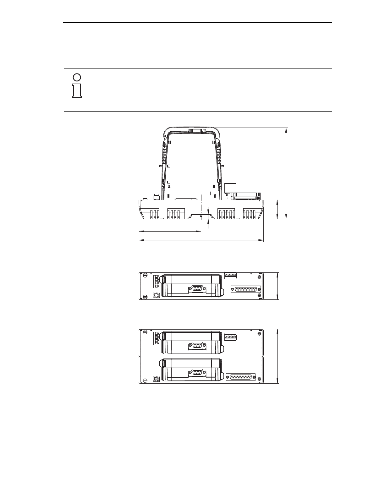
2.8 Dimensions
•
All dimensions in millimeters and inches (values in brackets) and without
tolerance indication.
Note
50 (1.9)
35 (1.3)
162 (6.3)
8
110 (4.3)
220 (8.6)
95 (3.7)
MB-FB-GT
MB-FB-GTR
Page 22

PROFIBUS POWER HUB SEGMENT COUPLER
Installation and Commissioning
Subject to reasonable modifications due to technical advances. Copyright Pepperl+Fuchs, Printed in Germany
Pepperl+Fuchs Group • Tel.: Germany +49 621 776-0 • USA +1 330 4253555 • Singapore +65 67799091 • Internet http://www.pepperl-fuchs.com
22
Date of Issue 24.3.11
3 Installation and Commissioning
3.1 Mounting and Dismounting
Mounting Motherboards on a DIN rail
To mount a motherboard, proceed as follows:
1. Place the motherboard on the DIN rail.
2. Tighten the fastening screw in the middle of the motherboard to attach the motherboard to the DIN rail.
The motherboard is mounted. Dismounting is performed in the reverse
order.
•
Mounting of HD2-* modules on the Motherboard
To install a new module on the motherboard, proceed as follows.
1. Carefully center the polarisation holes and mate the two connectors, then gently press down the module.
2. Push down the red Quick Lok bars on each side of the module to
fix it to the panel (no tools required).
The new module is installed.
•
Page 23
PROFIBUS POWER HUB SEGMENT COUPLER
Installation and Commissioning
Subject to reasonable modifications due to technical advances. Copyright Pepperl+Fuchs, Printed in Germany
Pepperl+Fuchs Group • Tel.: Germany +49 621 776-0 • USA +1 330 4253555 • Singapore +65 67799091 • Internet http://www.pepperl-fuchs.com
23
Date of Issue 24.3.11
Dismounting of HD2-* modules from the Motherboard
To dismount a module from the motherboard, proceed as follows:
Push the red Quick Lok bars upwards and gently lift off the entire
module.
The module is removed.
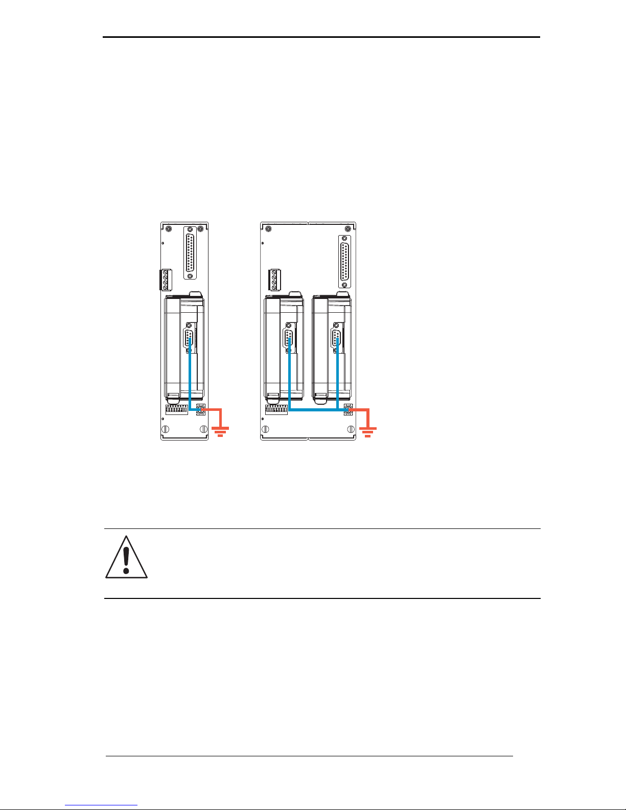
3.2 Shield/Grounding
•
The screen/shield of the Profibus cable on the HD2-GTR-4PA is connected directly to the screen/ground connection clamp of the motherboard.
If the Profibus DP cable leads into a hazardous area the screen/ground
connection clamp has to be connected to safety earth.
There might be a requirement to earth all exposed metal parts as a matter of course.
•
Earth Connection
Take care about good earthing practice and ensure a clean earth at all
times.
MB-FB-GT
MB-FB-GTR
Attention
Page 24
PROFIBUS POWER HUB SEGMENT COUPLER
Installation and Commissioning
Subject to reasonable modifications due to technical advances. Copyright Pepperl+Fuchs, Printed in Germany
Pepperl+Fuchs Group • Tel.: Germany +49 621 776-0 • USA +1 330 4253555 • Singapore +65 67799091 • Internet http://www.pepperl-fuchs.com
24
Date of Issue 24.3.11
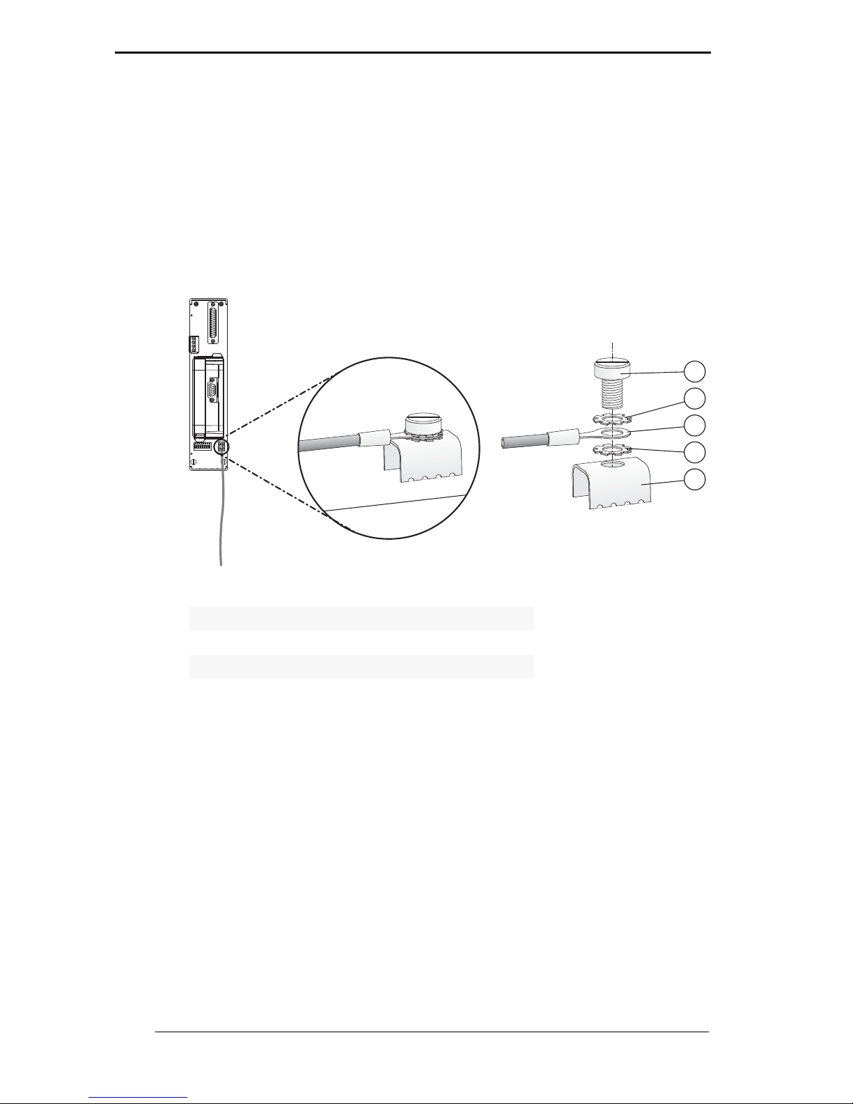
Connecting the ground connection cable
1. Connect the ground cable to a cable lug.
2. Position the cable lug over the ground connection clamp so that
the cable points downwards.
3. Screw the cable lug to the ground connection clamp using two toothed lock washers.
4. Tighten the screw so that the cable lug can not move.
•
1Screw
2 Toothed lock washer
3Cable lug
4 Ground connection clamp on motherboard
1
2
3
4
2
Page 25
PROFIBUS POWER HUB SEGMENT COUPLER
Installation and Commissioning
Subject to reasonable modifications due to technical advances. Copyright Pepperl+Fuchs, Printed in Germany
Pepperl+Fuchs Group • Tel.: Germany +49 621 776-0 • USA +1 330 4253555 • Singapore +65 67799091 • Internet http://www.pepperl-fuchs.com
25
Date of Issue 24.3.11
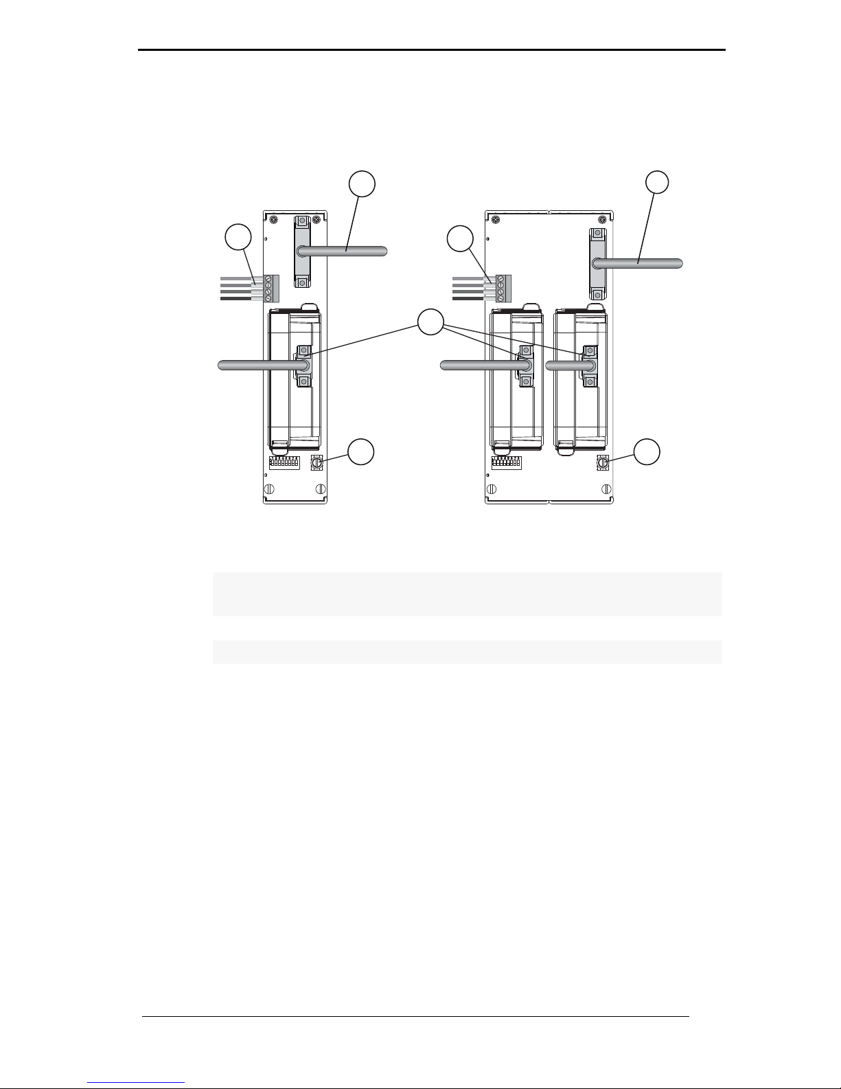
3.3 Connections
•
1 Sub-D connection to Power Hub motherboard MB*-FB*.GEN using
ACC-MB-HGC link cable
2 Diagnostics coupling to neighboring Power Hub motherboard using
ACC-MB-HDC link cable (optional, see also next page)
3 PROFIBUS DP connection
4 Ground connection clamp
MB-FB-GT
MB-FB-GTR
2
3
4
1
1
2
4
Page 26
PROFIBUS POWER HUB SEGMENT COUPLER
Installation and Commissioning
Subject to reasonable modifications due to technical advances. Copyright Pepperl+Fuchs, Printed in Germany
Pepperl+Fuchs Group • Tel.: Germany +49 621 776-0 • USA +1 330 4253555 • Singapore +65 67799091 • Internet http://www.pepperl-fuchs.com
26
Date of Issue 24.3.11
•
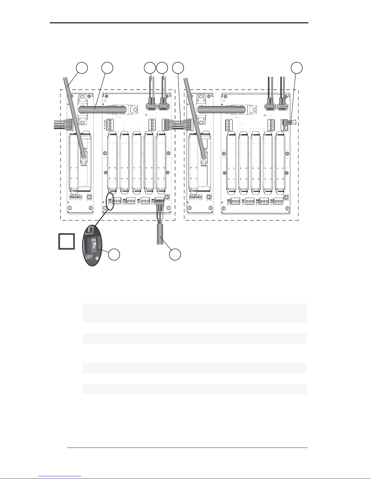
Figure 3.1: Connections of the PROFIBUS Power Hub system
1
PROFIBUS DP connection
2 ACC-MB-HGC link cable connecting Gateway motherboard and
Power Hub motherboard
3 Primary power supply connection
4 Secondary power supply connection
5 ACC-MB-HDC diagnostic link cable connecting neighboring Power
Hubs (optional, read following note)
6 Final motherboard link (optional, read following note)
7Trunk
8 Terminator
T
2
3 4
5
6
7
1
8
Page 27

PROFIBUS POWER HUB SEGMENT COUPLER
Installation and Commissioning
Subject to reasonable modifications due to technical advances. Copyright Pepperl+Fuchs, Printed in Germany
Pepperl+Fuchs Group • Tel.: Germany +49 621 776-0 • USA +1 330 4253555 • Singapore +65 67799091 • Internet http://www.pepperl-fuchs.com
27
Date of Issue 24.3.11
3.3.1 Master Connection to a Redundant PROFIBUS Power Hub System
•
Normally, diagnostic information from the diagnostic module HD2-DM* is
transmitted via the gateway. You do not need to connect neighboring Power Hubs.
Alternatively, you may bypass the gateway and transmit the diagnostic information via a separate bus. Only in this case do you need to connect
neighboring power hubs using the ACC-MB-HDC diagnostic link cable.
The last Power Hub in a row has to be fitted with a final motherboard link
(see figure 3.1).
Note
*Flying Redundancy
Master 1
Master 2*
Page 28

PROFIBUS POWER HUB SEGMENT COUPLER
Installation in Hazardous Areas
Subject to reasonable modifications due to technical advances. Copyright Pepperl+Fuchs, Printed in Germany
Pepperl+Fuchs Group • Tel.: Germany +49 621 776-0 • USA +1 330 4253555 • Singapore +65 67799091 • Internet http://www.pepperl-fuchs.com
28
Date of Issue 24.3.11
4 Installation in Hazardous Areas
4.1 Installation in Zone 2 Category 3G
The PROFIBUS Power Hub Segment Coupler may be installed in
Zone 2 Category 3G. The protection class is EEx nA C (non-arcing) gas
group IIC, IIB, IIA. Depending on the type of Power Modules used, different topologies and Zone 2 installations can be implemented.
The Fieldbus trunk is always categorized as EEx nA for Zone 2 applications. Connecting the PROFIBUS Power Hub with the Pepperl+Fuchs
Segment Protector (SPs) allows hot swapping of field devices.
Special safety instructions
EC type examination certificates and EC Certificates of Conformity and/
or the manufacturer’s Declaration of Conformity must be observed. It is
especially important to observe the "Special Conditions" included in
these documents.
•
Connections of non-energy-limited circuits under voltage may only be
made or disconnected during installation or maintenance or for repair
purposes.
•
If it is mounted in the hazardous area of Zone 2 Category 3G, the device
must be mounted in a housing, corresponding to at least protection class
IP 54 in accordance with EN 60529 and suitable for this type of installation.
•
The possibility of an explosive atmosphere occurring during installation,
maintenance or repairs is evaluated as improbable in Zone 2.
•
Devices that have been operated in general electrical plants must not be
used again after that in electrical plants that are connected to hazardous
areas.
Warning
Warning
Warning
Warning
Page 29

PROFIBUS POWER HUB SEGMENT COUPLER
PROFIBUS Commissioning
Subject to reasonable modifications due to technical advances. Copyright Pepperl+Fuchs, Printed in Germany
Pepperl+Fuchs Group • Tel.: Germany +49 621 776-0 • USA +1 330 4253555 • Singapore +65 67799091 • Internet http://www.pepperl-fuchs.com
29
Date of Issue 24.3.11
5 PROFIBUS Commissioning
5.1 Assigning a Device Address
After the module is mounted, a slave address must be assigned to the
Built-In-Slave of Gateway HD2-GTR-4PA. This assignment is performed
only via the DIP switch on the Motherboard.
The DIP switch consists of 8 switches positioned next to each other.
They can be used to assign addresses from 0 to 255 in binary form
(2
8
=256).
Assigning the Built-In-Slave Address
To assign an address to the Built-In-Slave of the Gateway HD2-GTR4PA, follow these steps:
1. Place the eight individual switches of the DIP switch in the correct positions to generate the desired address of the Built-InSlave as the sum of powers of two from left to right (see the label on the Gateway Module).
2. Restart the Gateway by disconnecting it from the power supply or
by unplugging the Gateway Module and reconnecting it.
The Built-In-Slave address is assigned.
5.2 Commissioning of Cyclic Data Exchange
An appropriate configuration tool is required to configure cyclic data exchange (defining the slave, effective data, etc.) with a PROFIBUS-DP
Master Class 1.
In non-redundant operation, Built-In-Slave addresses are permitted in
the range from 0-125; in redundant operation, addresses between 0 and
61 are permitted.
Assigning an invalid address for the type of operation in question causes
the Built-In-Slave to be deactivated.
In redundant operation, an address must be assigned to the Built-InSlave.
In the case of redundant coupling, both Gateways need to be restarted
at the same time.
Note
Note
Note
Page 30
PROFIBUS POWER HUB SEGMENT COUPLER
PROFIBUS Commissioning
Subject to reasonable modifications due to technical advances. Copyright Pepperl+Fuchs, Printed in Germany
Pepperl+Fuchs Group • Tel.: Germany +49 621 776-0 • USA +1 330 4253555 • Singapore +65 67799091 • Internet http://www.pepperl-fuchs.com
30
Date of Issue 24.3.11
Commissioning of Simplex System and Redundant System
The following section describes communication start-up of the
HD2-GTR-4PA:
1. If necessary, convert existing GSD files of PA slaves with the
P+F-GSD converter and then integrate them into the configuration tool
2. Integrate the GSD file of the HD2-GTR-4PA into the configuration
tool
3. Add Built-In-Slave (BIS) of the HD2-GTR-4PA to the DP bus configuration
4. Assign the BIS address set on the Motherboard DIP switch to the
HD2-GTR-4PA on the DP bus
5. Adjust the Watchdog. Rough value: 5 seconds (see chapter “Additional Information about Watchdog time” on page 33)
Additional steps for Redundant Coupling
The following additional steps are required for redundant coupling:
1. Add the Built-In-Slave (BIS) of the second DP/PA Gateway to
the DP bus configuration
2. Assign the BIS address set on the DP bus (the address of the first
BIS + 64) to the second DP/PA Gateway on the DP bus.
Additional steps for use of fiber-optical zones
If Coupling is designed redundantly and the DP bus uses optical fiber
as a communication medium, the following additional steps must be
performed:
Adjust the retry limit according to the baudrate (see chapter “Additional Information on Adjusting Retry” on page 35).
Because the DP/PA-Gateway is already a DP slave, its device GSD does
not need to be converted. The GSD file of the HD2-GTR-4PA is available
for download at www.pepperl-fuchs.com.
•
PA slaves do not take part in cyclic data exchange
The Built-In-Slave (BIS) of the first DP/PA Gateway must take part in cyclic data exchange. If it does not the connected PA slaves will also not
enter into cyclic data exchange.
Add the BIS of the Gateway to the DP bus configuration!
Note
Attention
Page 31

PROFIBUS POWER HUB SEGMENT COUPLER
PROFIBUS Commissioning
Subject to reasonable modifications due to technical advances. Copyright Pepperl+Fuchs, Printed in Germany
Pepperl+Fuchs Group • Tel.: Germany +49 621 776-0 • USA +1 330 4253555 • Singapore +65 67799091 • Internet http://www.pepperl-fuchs.com
31
Date of Issue 24.3.11
5.2.1 Information on the GSD Conversion
Because coupling is transparent, PROFIBUS PA nodes are treated like
PROFIBUS DP slaves by the PROFIBUS DP Master. This also applies
to start-up and configuration.
The GSD file must be integrated in a configuration tool before it can be
used to configure and operate a PROFIBUS PA slave.
The following distinctions are important to recognize in GSD files for
PROFIBUS PA slaves:
• Is the file a profile GSD or a manufacturer-specific GSD?
• is the GSD designed for communication via the RS 485 interface (DP-GSD) or by the interface in conformity with
IEC 61158-2 (PA-GSD)?
If a profile GSD is being used, the filename indicates whether it is a DPGSD or a PA-GSD. For example, file PA039733.gsd is the profile GSD
for 4 binary outputs. The "PA“ in the filename means it is a PROFIBUS
PA slave. The following "0“ indicates it is a DP-GSD. The filename of the
PA-GSD for the same profile is PA139733. The "1“ after the PA abbreviation identifies it as a PA-GSD.
If manufacturer-specific GSDs are used, for example to make use of
functionality that falls outside the profile, the following convention identifies whether it is a DP-GSD or PA-GSD:
• If you have not done so already, integrate the GSD into your
configuration tool.
• Check in your configuration tool what baud rates are supported.
If a baudrate of 31.25 kBd is supported, the file is a PA-GSD. Normally
only baudrates of 31.25 kBd, 45.45 kBd and 93.75 kBd are supported
by the PA-GSD.
If transmission rates in accordance with the PROFIBUS specification
are used (IEC 61158), i.e. baudrates of 9.6 kBd to 1.5 MBd or 12 MBd,
the file is a DP-GSD. Some PROFIBUS PA field device manufacturers
do not offer any PROFIBUS DP-GSDs. In this case the existing PROFIBUS PA-GSD must be converted. The conversion software (GSD converter) is available at no cost from www.pepperl-fuchs.com. The purpose of this conversion software is exclusively to enter missing
transmission rates and to set specific bus parameters to values that allow for problem-free operation of the PROFIBUS DP.
Converting the GSD file imposes the following functional restrictions if
that was previously supported by the original GSD file:
• FREEZE and SYNC functionality is deactivated. These
functions are used in PROFIBUS DP for synchronization of sensors/actuators. Since work is possible on the PROFIBUS DP
Page 32

PROFIBUS POWER HUB SEGMENT COUPLER
PROFIBUS Commissioning
Subject to reasonable modifications due to technical advances. Copyright Pepperl+Fuchs, Printed in Germany
Pepperl+Fuchs Group • Tel.: Germany +49 621 776-0 • USA +1 330 4253555 • Singapore +65 67799091 • Internet http://www.pepperl-fuchs.com
32
Date of Issue 24.3.11
side (Host side) at transmission speeds of up to 12 MBd and on
the PROFIBUS PA side (field side) at a rate of 31.25 MBd, problem-free operation cannot be guaranteed.
Some PROFIBUS functions are not currently supported. If the field device is intended to support one or more of the following functions, a
warning will point out that this will no longer be the case after the conversion. This affects the following functions:
• Master class 1 acyclic access
The following functions of PROFIBUS DP V2:
• Data Exchange Broadcast (Publisher/Subscriber)
• Isochronous mode, i.e. cycle-synchronous transmission
Using the Pepperl+Fuchs GSD converter
To convert GSD files, follow these steps:
1. Start program PFGSDCX.EXE
The following dialog appears:
•
2. Select the directory that contains the GSD files you wish to convert.
3. Select the GSD files you wish to convert.
The Advisory Board of the PROFIBUS User Organization has agreed
that certified GSD files changed by the Pepperl+Fuchs GSD converter
software will not lose their certificate.
Note
Page 33

PROFIBUS POWER HUB SEGMENT COUPLER
PROFIBUS Commissioning
Subject to reasonable modifications due to technical advances. Copyright Pepperl+Fuchs, Printed in Germany
Pepperl+Fuchs Group • Tel.: Germany +49 621 776-0 • USA +1 330 4253555 • Singapore +65 67799091 • Internet http://www.pepperl-fuchs.com
33
Date of Issue 24.3.11
4. Select the directory where you would like to store the converted
GSD files.
5. Convert the GSD files by clicking on the "Process GSD -->“ button
Another window appears with information about the result of the conversion process.
5.2.2 Additional Information about Watchdog time
PROFIBUS devices can activate a mechanism that monitors each time
interval in the cyclic data exchange process (also referred to as user
data exchange) to ensure that the PROFIBUS master is still active. The
time is measured in the PROFIBUS slave.
If the response monitor is active and the time (TWD) since the last cyclic
polling process has expired, the device stops the cyclic data exchange,
reverts to its original status (Wait_prm) and secures the status of the
outputs.
The time value TWD and the signal for activating the response monitor
are transmitted from the PROFIBUS master to the PROFIBUS slave in
the parameter telegram at start-up (transmitted during the cyclic data
exchange). The time T
WD
is generally defined specific to the user (not
device-specific, not in the GSD). Lesser values are limited by the cycle
times.
The time TWD is usually entered via the configuration tool. The watchdog setting in the DP/PA gateway is transparent. On some configuration
tools, the response monitor is preset once for the PROFIBUS master.
You can select one or more files for conversion by pressing the CTRL or
SHIFT keys. Files preceded by a "+" symbol are the result of a previous
conversion. These files cannot be converted again and an error message
appears if an attempt is made to do so. Files beginning with a "-" symbol
have not been converted and can be if required. Double-click to open and
view or edit a file.
•
Watchdog reprogramming during cyclic communication!
DPV1 slaves leave cyclic communication because the DPV1 standard
does not permit any Watchdog change during operation.
The BIS of the DP/PA Gateway performs diagnostics in the DTM and cyclically to determine whether the Watchdog time (TWD) is sufficient.
Note
Warning
Note
Page 34

PROFIBUS POWER HUB SEGMENT COUPLER
PROFIBUS Commissioning
Subject to reasonable modifications due to technical advances. Copyright Pepperl+Fuchs, Printed in Germany
Pepperl+Fuchs Group • Tel.: Germany +49 621 776-0 • USA +1 330 4253555 • Singapore +65 67799091 • Internet http://www.pepperl-fuchs.com
34
Date of Issue 24.3.11
While on other tools, the response monitor is preset individually for each
PROFIBUS PA participant. The response monitor value does not change in any way.
Many tools calculate the time TWD automatically with a corresponding
baud rate based on the cycle time of the master.
If the baud rates at the PROFIBUS DP end are high (e.g. 12 MBd), the
cycle times of the PA end may be 300 times longer. If a PROFIBUS PA
device has been programmed directly with a time TWD calculated at a
higher master baud rate (DP), this is usually shorter than the PA cycle
and the device does not exchange data.
The following bus parameters should be used to ensure the DP/PA gateway operates reliably:
• only one watchdog time T
WD
is programmed for the entire
PROFIBUS system. The longest delay period must be determined in order to define T
WD
• one watchdog time TWD is programmed for each individual slave.
The preset (parameterized) time TWD must be greater than the maximum occurring delay period T
V_max
.
Two types of Watchdogs can be configured on the HD2-GTR-4PA in cyclic or acyclic data exchange (chapter “Watchdog Time in the DTM” on
page 48):
• Transparent Watchdog: The Watchdog time on the DP side is
the same as on the PA side (= default setting).
• Fixed Watchdog: A Watchdog time is set on the HD2-GTR-4PA
for the PA side that is different than the DP side.
5.2.3 Information about I/O Cycle Time
The overall I/O data cycle time from a DP master via HD2-GTR-4PA to
a PA slave can be approximated as follows:
T
Cycle_IO_Data
= T
Cycle_DP
+ T
Cycle_PA_Channel
where:
T
Cycle_PA_Channel
= Cycle time of the PROFIBUS PA channel
T
Cycle_DP
= Cycle time of the PROFIBUS DP
The HD2-GTR-4PA measures the current cycle time of each PA segment
and generates a diagnostic message if the Watchdog time is too short.
Then the Watchdog time must be increased. The Gateway diagnostics
are based on the following formula: 2 x T
Cycle_PA_Channel
+ 500 ms
Note
Page 35

PROFIBUS POWER HUB SEGMENT COUPLER
PROFIBUS Commissioning
Subject to reasonable modifications due to technical advances. Copyright Pepperl+Fuchs, Printed in Germany
Pepperl+Fuchs Group • Tel.: Germany +49 621 776-0 • USA +1 330 4253555 • Singapore +65 67799091 • Internet http://www.pepperl-fuchs.com
35
Date of Issue 24.3.11
The PA cycle time T
Cycle_PA_Channel
depends on:
• the number n of nodes on a channel
• the effective data length L
The effective data length L is a unitless variable calculated as the sum
of input and output effective data quantity (in bytes) of all devices.
The cycle time is calculated approximately as follows:
Nonredundant system:
T
Cycle_PA_Channel
= (0.256 ms * L) + (n * 12 ms) + 40 ms
Redundant system:
T
Cycle_PA_Channel
= (0.256 ms * L) + (n * 12 ms) + 100 ms
5.2.4 Additional Information on Adjusting Retry
If the coupling from DP to PA is designed redundantly and the DP bus
uses optical fiber as a communication medium, Pepperl+Fuchs recommends increasing the retry limit of the DP master.
Recommended retry limits corresponding to various baudrates:
5.3 DTM Software Installation and Commissioning
System requirements for installation, commissioning and operation of
the DP/PA Gateway DTM:
• Hardware requirements based on your frame FDT
• FDT frame application (FDT specification 1.2)
• Latest version of HD2-GTR-4PA-DTM
•
Cycle time discrepancy in real application
This is the basic cycle time for ideal conditions. In reality acyclic communication, retries and diagnosis data can increase the cycle time so an additional safety margin has to be added. For the calculation of a overall
cycle time (Change of a measured signal until reaction of an Actuator)
additional parameters like the measurement cycle time of the PROFIBUS
PA devices and IO Processing cycle of the controller must be considered.
Baudrate Retry limit
45.45 kBd 2
93.75 kBd 2
187.5 kBd 2
1.5 MBd 2
3 MBd 4
6 MBd 6
12 MBd 7
Attention
Page 36

PROFIBUS POWER HUB SEGMENT COUPLER
PROFIBUS Commissioning
Subject to reasonable modifications due to technical advances. Copyright Pepperl+Fuchs, Printed in Germany
Pepperl+Fuchs Group • Tel.: Germany +49 621 776-0 • USA +1 330 4253555 • Singapore +65 67799091 • Internet http://www.pepperl-fuchs.com
36
Date of Issue 24.3.11
• 40 MB free hard drive storage
Installation of DTM Package with PACTware
TM
as an Example
To install the DTM package on your system, follow these steps:
1. Install the P+F-FieldConnex
R
DTM package
2. Start the PACT
ware
TM
program
3. Update the device catalog
•
The Create New Device Catalog window appears:
•
4. Confirm with YES
The DTM is installed and ready for operation.
Create the project tree
To create the project tree, proceed as follows:
1. Start PACT
ware
TM
2. Open the appropriate project or create a new one
3. Open the device catalog (View/Device Catalog or press F3)
Make sure that all PACT
ware
TM
projects are closed.
Make sure the latest DTM version is installed and that the device catalog
is updated.
Note
Note
Page 37
PROFIBUS POWER HUB SEGMENT COUPLER
PROFIBUS Commissioning
Subject to reasonable modifications due to technical advances. Copyright Pepperl+Fuchs, Printed in Germany
Pepperl+Fuchs Group • Tel.: Germany +49 621 776-0 • USA +1 330 4253555 • Singapore +65 67799091 • Internet http://www.pepperl-fuchs.com
37
Date of Issue 24.3.11
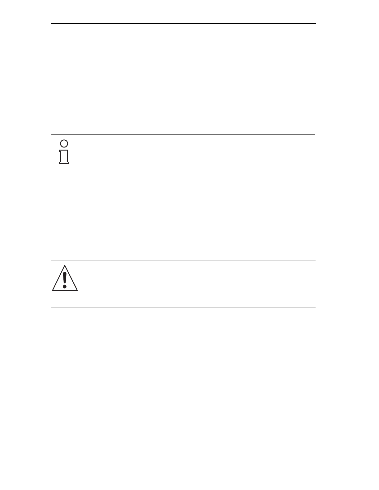
4. Open the menu entry Softing AG
•
5. Select the entry Drivers/PROFIBUS Driver
•
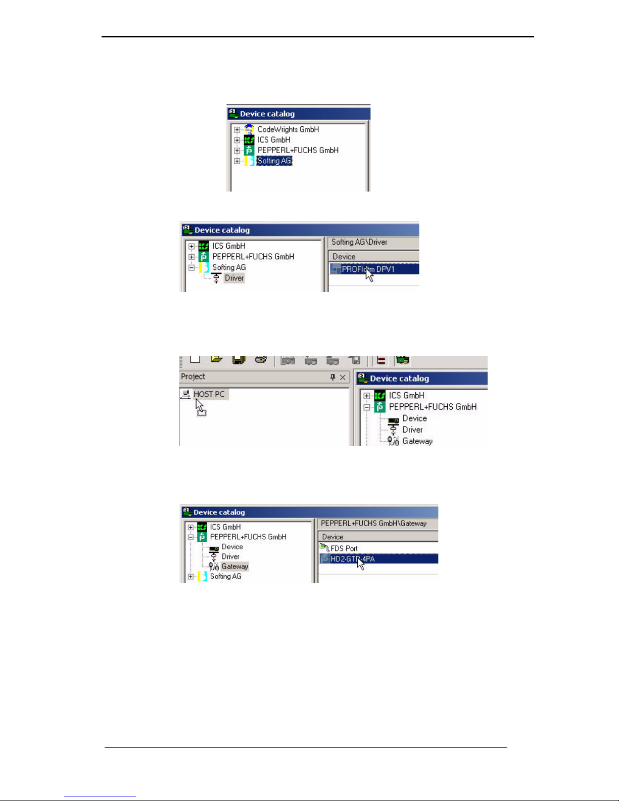
6. Drag and drop the PROFIBUS Driver to your project window/Host
PC
•
7. In the Device Catalog, open menu item Pepperl+Fuchs GmbH/
Device/HD2-GTR-4PA
•
Page 38

PROFIBUS POWER HUB SEGMENT COUPLER
PROFIBUS Commissioning
Subject to reasonable modifications due to technical advances. Copyright Pepperl+Fuchs, Printed in Germany
Pepperl+Fuchs Group • Tel.: Germany +49 621 776-0 • USA +1 330 4253555 • Singapore +65 67799091 • Internet http://www.pepperl-fuchs.com
38
Date of Issue 24.3.11
8. Drag the HD2-GTR-4PA into the project window into the PRO-
FIdtm DPV1 node. The window Add station address will appear.
•
9. Enter the station address (BIS address of the Gateway) and confirm with OK.
Your project tree should now look like this:
•
Enter assigned BIS address in the DTM
To enter the BIS address (which has been assigned on the Gatewaymotherboard) into the DTM, proceed as follows:
1. Rightclick on PROFIdtm DPV1 in the project tree and choose
Additional Functions/Edit DTM Station Addresses.
2. Enter the BIS address set on the Gateway Motherboard and confirm with Apply:
•
In rare cases, the FDT application may not immediately display the
address change in the project window even though the change has been
made.
In that case, save the project once to update the display.
Note
Page 39

PROFIBUS POWER HUB SEGMENT COUPLER
PROFIBUS Commissioning
Subject to reasonable modifications due to technical advances. Copyright Pepperl+Fuchs, Printed in Germany
Pepperl+Fuchs Group • Tel.: Germany +49 621 776-0 • USA +1 330 4253555 • Singapore +65 67799091 • Internet http://www.pepperl-fuchs.com
39
Date of Issue 24.3.11
Advanced Diagnostic Module Engineering
To integrate an Advanced Diagnostic Module HD2-DM-A via
PROFIBUS PA, proceed as follows:
1. In the device catalog, open
PEPPERL+FUCHS GmbH/Device/HD2-DM-A
2. Drag&Drop HD2-DM-A into the project window’s HD2-GTR-4PA
node
Your project tree should now look as follows:
•
3. To assign a tag to the Advanced Diagnostic Module, open the offline dialog of HD2-GTR-4PA.
4. Enter a device description into the field ADM Tag and confirm with
Enter
•
•
Data loss
The Advanced Diagnostic Module can be engineered in both the offline
and the online dialog. Make sure to load the data from the device or to
the device after engineering.
The ADM address is being detected automatically and is displayed symbolically by „999“. There is no need to assign an address.
Attention
Note
Page 40

PROFIBUS POWER HUB SEGMENT COUPLER
Operation
Subject to reasonable modifications due to technical advances. Copyright Pepperl+Fuchs, Printed in Germany
Pepperl+Fuchs Group • Tel.: Germany +49 621 776-0 • USA +1 330 4253555 • Singapore +65 67799091 • Internet http://www.pepperl-fuchs.com
40
Date of Issue 24.3.11
6 Operation
In PROFIBUS, two types of communication exist:
• cyclic and
• acyclic data exchange.
In cyclic data exchange, user data is exchanged between the Master
(Process Control System) and Slave (field device) at regular intervals.
User data includes measurement values, limit position feedback and
output data, etc. The bus cycle time depends essentially on the number
of nodes and the amount of data being transmitted.
In acyclic data exchange, "service" data, for example device parameterization or diagnostic information, is transmitted.
A number of parameters of the HD2-GTR-4PA Gateway Module can be
adjusted both through acyclic parameterization (using the DTM) and via
the Process Control System. The advantage of parameterization via the
Process Control System is the simplification of device replacement
since no additional effort is required in addition to replacing the physical
device.
6.1 Built-In-Slave (BIS) Description
The Gateway has an integrated slave (Built-In-Slave or "BIS“) with a DP
address that can be configured with the DIP switch on the Motherboard.
As a device participating in cyclic data exchange, the BIS returns
function monitoring and diagnostic data to the Master.
6.1.1 Cyclic Data Exchange
The BIS is a modular DPV1 slave with one slot. Two modules are available, each with a one-byte input and one-byte output. The input provides a combined status message for the Gateway. The status message
is coded as a PA Profile Status Byte (0x00: Bad unspecific, 0xA4: Good
Maintenance Required, 0x80: Good). For the actual value of the byte
under certain diagnosis conditions, please refer to table “Device Diagnosis Parameters” on page 42. If multiple diagnosis events are present,
the priority is as follows: Bad (highest priority), Good Maintenance required, Good (lowest priority). A dummy byte (0x00) must be sent as an
output data item.
6.1.2 Parameterization Options (Channel Assignment)
The three configuration modules Default, PA-BUS Configuration and
PA-BUS Configuration + Diag allow the parameterization of the following values:
Page 41

PROFIBUS POWER HUB SEGMENT COUPLER
Operation
Subject to reasonable modifications due to technical advances. Copyright Pepperl+Fuchs, Printed in Germany
Pepperl+Fuchs Group • Tel.: Germany +49 621 776-0 • USA +1 330 4253555 • Singapore +65 67799091 • Internet http://www.pepperl-fuchs.com
41
Date of Issue 24.3.11
6.1.3 Diagnostics (Slave Diagnostics)
The BIS returns the following of the diagnostic blocks described in the
GSD:
• Device Diagnosis
• 0- 4 x Segment Diagnosis (Channel Diagnosis)
• RedState-Block
Device Diagnosis provides specific diagnostic information about the Gateway. This information is parsed directly by the Process Control System
and displayed for the user. In redundant configuration, all diagnosis information is also available for the redundancy partner. Device Diagnosis
includes:
Default
none
PA-BUS Configuration
Watchdog Time
PA Retry limits
Number of activated PA segments
PA-BUS Configuration + Diag
Watchdog time
PA Retry limits
Number of activated PA segments
Diagnosis (ADM Alarm Observer)
If the PA bus configuration module is set, values that are set with this module cannot be changed with acyclic access during cyclic communication.
Note
Page 42

PROFIBUS POWER HUB SEGMENT COUPLER
Operation
Subject to reasonable modifications due to technical advances. Copyright Pepperl+Fuchs, Printed in Germany
Pepperl+Fuchs Group • Tel.: Germany +49 621 776-0 • USA +1 330 4253555 • Singapore +65 67799091 • Internet http://www.pepperl-fuchs.com
42
Date of Issue 24.3.11
All Device Diagnostic parameters marked with „Yes“ in the EXT_DIAG
column cause the EXT_DIAG to be set in the slave diagnosis. The Process Control System then marks that slave as defective.
Device Diagnosis
Parameters
EXT_DIAG InputData
Gateway primary device
No GOOD
Redundancy not operative
Ye s BAD
Redundancy is
syncronizing
Ye s B A D
Redundancy gateway
missing
Ye s BAD
Hardware error
detected
Ye s B A D
Redundancy link
error
Ye s BAD
No baudrate detected Yes BAD
BuiltIn-Slave
not in data exchange
No
GOOD
Firmware version
mismatch
Ye s B A D
Firmware updated,
need reboot
Ye s BAD
A PA Masters not in
token ring
Ye s B A D
PABus parameters
write locked
No GOOD
Segment MAU error Yes BAD
ADM error
or module missing
Ye s BAD
ADM: system maintenance required
Yes GOOD Maintenance
required
ADM: system out of
specification
Ye s BAD
ADM: segment
maintenance required
Yes GOOD Maintenance
required
ADM: segment out of
specification
Ye s BAD
Page 43

PROFIBUS POWER HUB SEGMENT COUPLER
Operation
Subject to reasonable modifications due to technical advances. Copyright Pepperl+Fuchs, Printed in Germany
Pepperl+Fuchs Group • Tel.: Germany +49 621 776-0 • USA +1 330 4253555 • Singapore +65 67799091 • Internet http://www.pepperl-fuchs.com
43
Date of Issue 24.3.11
Channel Diagnostics returns specific diagnostic information about each
individual segment. These error messages are prioritized and set to
preferred by the BIS depending on their ranking. The following table represents diagnostic information according to its ranking.
The RedState Block is a standardized diagnostic block, it is inserted
when the slave receives a PRM command.
6.2 Coupled Slaves
This section applies to coupled slaves on non-redundant Masters and
to Flying Redundancy Masters.
All coupled PA slaves behave as non-redundant DP slaves after the
GSD conversion, so that every PA slave appears directly on the DP bus.
The PA slaves are not merged to one single slave.
Both cyclic and acyclic communication is coupled.
As many C2 connections are coupled to the slaves as they support, al-
together a maximum of 500.
From the Master's point of view, redundancy switching of the Gateway
has no effect on PA slaves. They do not drop out of communication.
The FREEZE and SYNC modes are coupled, but because DP commu-
nication and PA communication are incompatible in terms of time, they
are not relevant for practical purposes.
Identification & Maintenance (I&M) Functions are supported.
6.3 Acyclic Data Exchange with BIS via DTM
The BIS supports four acyclic connections. Three dialogs are available
in acyclic mode via the DTM (Device Type Manager):
• the Offline Dialog
• the Online Dialog
• the Diagnostics Dialog
Channel Diagnostic parameters
Hardware Error
No slave in live list
DP Watchdog time too short
Duplicate slave address
PA master not in token ring
ADM: segment out of specification
ADM: segment maintenance required
Page 44

PROFIBUS POWER HUB SEGMENT COUPLER
Operation
Subject to reasonable modifications due to technical advances. Copyright Pepperl+Fuchs, Printed in Germany
Pepperl+Fuchs Group • Tel.: Germany +49 621 776-0 • USA +1 330 4253555 • Singapore +65 67799091 • Internet http://www.pepperl-fuchs.com
44
Date of Issue 24.3.11
In the Offline dialog, all parameters can be set locally without having any
direct effect on communication or the device. Data can be written to the
device after all settings have been made. Current parameters can also
be read in from the device, processed and saved.
In the Online Dialog, you directly effect device parameters. Your entry is
written to the device immediately, as soon as you press the Return key.
The Online Dialog additionally offers diagnostic information about the
Gateway and the PA-segments connected to the Power Hub.
The Diagnostic Dialog shows the current device parameters and
diagnostic information, changes to the data cannot be made in this dialog.
•
Figure 6.1: Functional overview of dialogs
6.3.1 Brief introduction to DTM with PACTwareTM as an Example
Connect DTM to the HD2-GTR-4PA
Make sure all settings have been made correctly (the device address,
etc.)
1. Right click in the project tree on HD2-GTR-4PA
2. Select Connect
A rhomb (#) next to the device icon in the project tree indicates that the
connection exists.
•
Data Loss
Settings made in the Online Dialog are not automatically transferred to
the Offline Dialog.
To save online settings, load the data into the
Offline Dialog (function: Read Data from Device).
Attention
Field device
Offline
dialog
Online
dialog
Upload
Download
Direct connection
Diagnosis
dialog
Diagnosis only
Page 45

PROFIBUS POWER HUB SEGMENT COUPLER
Operation
Subject to reasonable modifications due to technical advances. Copyright Pepperl+Fuchs, Printed in Germany
Pepperl+Fuchs Group • Tel.: Germany +49 621 776-0 • USA +1 330 4253555 • Singapore +65 67799091 • Internet http://www.pepperl-fuchs.com
45
Date of Issue 24.3.11
Open Offline Dialog
To open the Offline Dialog:
1. Right click in the project tree on HD2-GTR-4PA
2. Select Parameters/Offline Parameterization
Open Online Dialog
Make sure the HD2-GTR-4PA is connected.
To open the Online Dialog:
1. Right click in the project tree on HD2-GTR-4PA
2. Select Parameters/Online Parameterization
Open Diagnosis Dialog
Make sure the HD2-GTR-4PA is connected.
To open the Diagnosis Dialog:
1. Right click in the project tree on HD2-GTR-4PA
2. Select Diagnostics
Print Diagnostic Information
To print Diagnosis information:
1. Open the Diagnosis or the Online Dialog (see above)
2. Press the "Print Button“ in the DTM header
•
The diagnostic report Print Preview window appears
3. Click Print in the footer of the Print Preview window
•
The Printer Driver Selection menu appears
4. Select your printer and confirm the print job
Page 46

PROFIBUS POWER HUB SEGMENT COUPLER
Operation
Subject to reasonable modifications due to technical advances. Copyright Pepperl+Fuchs, Printed in Germany
Pepperl+Fuchs Group • Tel.: Germany +49 621 776-0 • USA +1 330 4253555 • Singapore +65 67799091 • Internet http://www.pepperl-fuchs.com
46
Date of Issue 24.3.11
6.3.2 Overview of the DTM User Interface
1 Identification area
2 Navigation area
3 Work area
4 Quick start
Page 47

PROFIBUS POWER HUB SEGMENT COUPLER
Operation
Subject to reasonable modifications due to technical advances. Copyright Pepperl+Fuchs, Printed in Germany
Pepperl+Fuchs Group • Tel.: Germany +49 621 776-0 • USA +1 330 4253555 • Singapore +65 67799091 • Internet http://www.pepperl-fuchs.com
47
Date of Issue 24.3.11
6.3.3 Structure Diagram
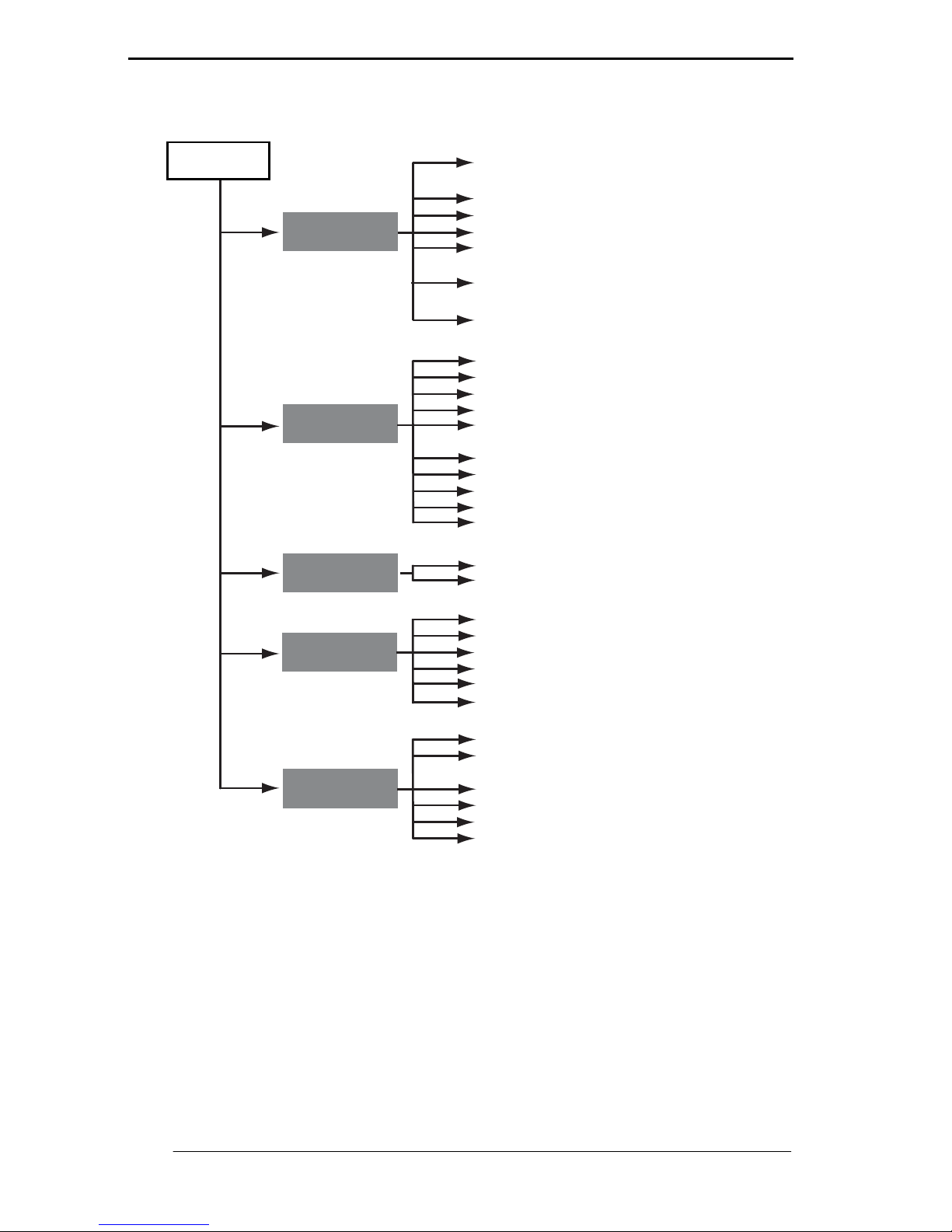
•
Figure 6.2: DTM structure - Offline Dialog
PA Master
HD2-GTR-4PA
Offline
Tag
Location
Descriptor
Signature
Segment Tags 1 ... 4
Activated PA segments
ADM Settings
ADM Alarm Observer
PA Retry Limit
Watchdog Mode
Installation Date
Device Settings
ADM Tag
PA Master Settings
Watchdog Time
PA Segment Tags
Slave Bus Parameter Set
Modul Configuration
Modul Configuration
Slave Bus Parameter Set
System
Settings
Channel
Assignment
Page 48
PROFIBUS POWER HUB SEGMENT COUPLER
Operation
Subject to reasonable modifications due to technical advances. Copyright Pepperl+Fuchs, Printed in Germany
Pepperl+Fuchs Group • Tel.: Germany +49 621 776-0 • USA +1 330 4253555 • Singapore +65 67799091 • Internet http://www.pepperl-fuchs.com
48
Date of Issue 24.3.11
•
Figure 6.3: DTM structure - Online Dialog
6.3.4 Watchdog Time in the DTM
The HD2-GTR-4PA has two Watchdog time settings:
• Transparent: The Watchdog time on the DP side is the same as
on the PA side.
• Fixed value: A Watchdog time is set on the HD2-GTR-4PA for
the PA side that differs from the time of the DP side.
HD2-GTR-4PA
Online
Tag
Location
Descriptor
Signature
Segment Tags 1 ... 4
Activated PA Segments
ADM Settings
ADM Alarm Observer
PA Retry Limit
Watchdog Mode
Installation Date
Device Parameters
PA Master Settngs
Watchdog Time
PA Segment Tags
Diagnosis (see chaper Diagnostics)
Summary Status
Detailed System Diagnosis
Tag
Installation Parameters
Device Metrics
Serial Number
Static Revision
Software Revision
Order Number
Mounting
PA Segment 1 ... 4
Summary Status
Tag
Number of devices
PA cycle time
Max. used retries
Diagnosis (see chaper Diagnostics)
Diagnosis (see chaper Diagnostics)
Summary Status
Redundancy Partner Diagnosis
Device Information
Installation Date
Serial Number
Software Revision
Mounting
Identification
Maintenance
System
Overview
System
Diagnosis
Segment
Diagnosis
Redundancy
Partner Diag.
Page 49

PROFIBUS POWER HUB SEGMENT COUPLER
Operation
Subject to reasonable modifications due to technical advances. Copyright Pepperl+Fuchs, Printed in Germany
Pepperl+Fuchs Group • Tel.: Germany +49 621 776-0 • USA +1 330 4253555 • Singapore +65 67799091 • Internet http://www.pepperl-fuchs.com
49
Date of Issue 15.5.12
When the HD2-GTR-4PA is delivered, the Watchdog setting is set by
default to transparent. You can find further information in chapter “Additional Information about Watchdog time” on page 33.
Set Fixed Watchdog Time via DTM
To change the Watchdog setting:
1. Open the Online or Offline dialog
2. Select "Fixed" from the drop-down list
•
3. Confirm the entry with Return
4. Enter the Watchdog time and confirm with Return
•
6.3.5 PA Retry Limit Setting
Parameters can also be set for the PA side retry limit in acyclic data exchange.
Set the PA Retry Limit via DTM
To set the PA retry limit in the DTM :
1. Open the Online or Offline Dialog
•
2. Select the retry limit from the drop-down list
3. Confirm your entry with Return
6.3.6 Restart Functions, Redundancy Switchover and Firmware Update
The HD2-GTR-4PA-DTM offers three additional functions:
•Restart,
• Restart with Default Values and
• Firmware Update.
Page 50

PROFIBUS POWER HUB SEGMENT COUPLER
Operation
Subject to reasonable modifications due to technical advances. Copyright Pepperl+Fuchs, Printed in Germany
Pepperl+Fuchs Group • Tel.: Germany +49 621 776-0 • USA +1 330 4253555 • Singapore +65 67799091 • Internet http://www.pepperl-fuchs.com
50
Date of Issue 24.3.11
Perform Restart
The function reboots the HD2-GTR-4PA.
1. Right click on HD2-GTR-4PA
2. Select Additional Functions/Restart
Restart is performed after confirmation.
Perform Restart with Default Values
The restart with Default Values function boots the HD2-GTR-4PA with
its default values. All manually configured data such as device tags,
Watchdog times and retry limits are lost.
To perform a restart with default values, proceed as follows:
1. Right click in the project tree on HD2-GTR-4PA
2. Select Additional Functions/Restart with Default Values
Restart is performed after confirmation.
Redundancy Switchover
The primary and secondary device exchange roles. The active BIS
drops out of communication. All coupled PA slaves remain in the data
exchange.
•
Loss of communication
If the coupling is simplex or redundancy is not available, all coupled PA
slaves drop out of the cycle.
•
Loss of communication
If the coupling is simplex or redundancy is not available, all coupled PA
slaves drop out of the cycle.
With redundant coupling, the device that has just restarted takes over all
configurations from the other device that is still active. To be able to reset
to default values in a redundant system, the restarted Gateway must be
mounted alone on the Motherboard.
•
Loss of communication
If redundancy is not available, all coupled PA slaves drop out of data exchange.
Before performing a switchover, check whether redundancy is available.
Attention
Attention
Note
Attention
Page 51

PROFIBUS POWER HUB SEGMENT COUPLER
Operation
Subject to reasonable modifications due to technical advances. Copyright Pepperl+Fuchs, Printed in Germany
Pepperl+Fuchs Group • Tel.: Germany +49 621 776-0 • USA +1 330 4253555 • Singapore +65 67799091 • Internet http://www.pepperl-fuchs.com
51
Date of Issue 24.3.11
To perform Redundancy Switching, proceed as follows:
1. Right click in the project tree on HD2-GTR-4PA
2. Select Additional Functions/Force Redundancy Switchover
After confirmation the function is performed.
Firmware Update
1. Right-click on HD2-GTR-4PA in the project tree
2. Choose Additional Functions/Firmware Download
3. Device identitfy appears, press Next
•
4. Choose the new Firmware file
•
Loss of communication
In the case of simplex coupling or if redundancy is unavailable, all coupled PA slaves leave cyclic communication.
Attention
Page 52
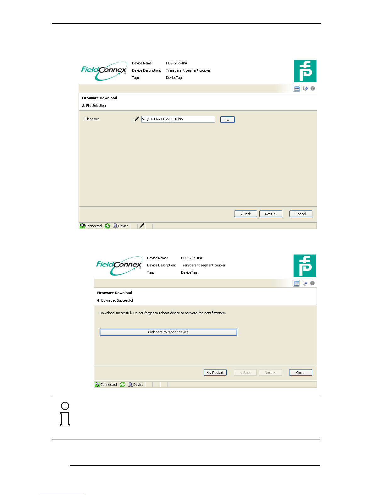
PROFIBUS POWER HUB SEGMENT COUPLER
Operation
Subject to reasonable modifications due to technical advances. Copyright Pepperl+Fuchs, Printed in Germany
Pepperl+Fuchs Group • Tel.: Germany +49 621 776-0 • USA +1 330 4253555 • Singapore +65 67799091 • Internet http://www.pepperl-fuchs.com
52
Date of Issue 24.3.11
5. Confirm the installation windows which follow by clicking Continue
•
6. Restart the Gateway
•
In the case of redundant coupling, a redundancy switchover occurs
when the Gateway is restarted. After this redundancy switchover has occurred, update the firmware (steps 1-5) for the second Gateway as well.
Note
Page 53

PROFIBUS POWER HUB SEGMENT COUPLER
Operation
Subject to reasonable modifications due to technical advances. Copyright Pepperl+Fuchs, Printed in Germany
Pepperl+Fuchs Group • Tel.: Germany +49 621 776-0 • USA +1 330 4253555 • Singapore +65 67799091 • Internet http://www.pepperl-fuchs.com
53
Date of Issue 24.3.11
6.4 Redundant Operation
6.4.1 Redundancy Behavior
During redundant operation, the Gateway simulates PA slaves for the
DP-BUS. From the point of view of the DP bus, Redundancy Switchover
has no visible effect on the Master. All slaves remain in the cycle. This
Transparent Redundancy (TR) differs from normal Flying Redundancy
(FR) behavior, which allows slaves to drop out of the cycle for a defined
time.
The HD2-GTR-4PA supports all Masters that work on the Flying Redundancy principle as well as all non-redundant Masters.
The BIS automatically detects whether the DP master is using a redundancy concept. If the DP master is working according to the Flying Redundancy concept, the Gateway automatically adjusts itself accordingly.
No settings of any kind need to be made.
With Transparent Redundancy, exchange of user data remains intact. In
the worst case, only non-critical acyclic data exchange will drop out.
6.4.2 System Environment for Redundant Operation
In redundant operation, both BISs (Primary and Backup Gateway)
should be in cyclic data exchange. Assigning bus addresses to both Gateways makes it easy to monitor both BISs with the Master, which detects the failure of one of the two BISs and reports the relevant slave
address.
The PROFIBUS Power Hub provides redundant Coupling of PA segments in the following system environments:
• with use of non-redundant Master and
• in a Flying Redundancy system.
Non-redundant Masters do not see any effect on PA slaves from Red-
undancy Switchover. The Backup Gateway takes over communication
seamlessly. Both Gateways participate in general Token Ring operation:
Primary Gateway = PA Master Address 1, Backup Gateway = PA Master
Address 2. Participation in Token Ring operation thus allows use of
handhelds for diagnostic purposes.
The BIS must participate in cyclic data exchange.
Note
Page 54

PROFIBUS POWER HUB SEGMENT COUPLER
Operation
Subject to reasonable modifications due to technical advances. Copyright Pepperl+Fuchs, Printed in Germany
Pepperl+Fuchs Group • Tel.: Germany +49 621 776-0 • USA +1 330 4253555 • Singapore +65 67799091 • Internet http://www.pepperl-fuchs.com
54
Date of Issue 24.3.11
In the FR environment all PA slaves are configurated as normal non-redundant slaves. The BIS can be configurated as an FR slave. For additional information, see chapter “Redundancy Concepts” on page 63.
•
Figure 6.4: Integration into Flying Redundancy and non-redundant system
6.4.3 Applications with Redundant Operation
Redundancy is available if:
• both Gateways are in operation with no errors
• both Gateways detect DP baudrates and
• there are no errors in PA communication.
Possible reasons for Redundancy Switchover are:
• Hardware error in the primary Gateway.
• Loss of baudrate (cable break, etc.).
• BIS drops out of the cycle (because of an unlock from the Master or the Watchdog time has expired, etc.).
Redundancy Switching has taken place if:
• both BISs have dropped out of communication and
• the primary BIS comes up again on the bus immediately or
• the BISs on the DP-BUS have changed roles.
The Primary Gateway is identifiable by:
• its LED „Red.“ (Redundancy) is flashing or being lit.
If redundant operation is not available, that will be reported by slave diagnostics.
PA slave
PA slave
PA slave
PA slave
*Flying Redundancy
primary
Gateway
backup
Gateway
Master 1 Master 2*
Note
Page 55

PROFIBUS POWER HUB SEGMENT COUPLER
Operation
Subject to reasonable modifications due to technical advances. Copyright Pepperl+Fuchs, Printed in Germany
Pepperl+Fuchs Group • Tel.: Germany +49 621 776-0 • USA +1 330 4253555 • Singapore +65 67799091 • Internet http://www.pepperl-fuchs.com
55
Date of Issue 24.3.11
If a Backup Gateway is plugged into the Motherboard:
• its BIS boots and
• it takes over all configurations from the Primary Gateway.
• The primary and secondary BISs are synchronized to each
other.
If a Gateway is separated from the redundant Motherboard:
• the primary device generates the diagnostic message "Redundancy not available, redundancy partner missing“.
•
Data loss
The reinstalled Gateway normally takes all configurations from the first
Gateway. All previous configurations of the new Gateway are overwritten.
Attention
Page 56

PROFIBUS POWER HUB SEGMENT COUPLER
Advanced Diagnostics with the PROFIBUS Power Hub
Subject to reasonable modifications due to technical advances. Copyright Pepperl+Fuchs, Printed in Germany
Pepperl+Fuchs Group • Tel.: Germany +49-621-776-0 • USA +1-330-4253555 • Singapore +65-67-799091 • Internet www.pepperl-fuchs.com
56
Date of Issue 24.3.11
7 Advanced Diagnostics with the PROFIBUS Power Hub
In conjunction with the Advanced Diagnostic Module HD2-DM-A, the
PROFIBUS Power Hub offers extensive analytic and monitoring possibilities for a PROFIBUS fieldbus installation. This diagnosis, from now
on called "Advanced Diagnostics", covers, among other things:
• proactive plant monitoring
• analysis of the Fieldbus Physical Layer (jitter, noise etc.)
• assistance during the complete fieldbus life cycle
• wizards for commissioning and fault detection
• integrated oscilloscope function
Further information regarding Advanced Diagnostics can be found in
the manual „Advanced Diagnostic Module HD2-DM-A“. You can download this manual from www.pepperl-fuchs.com.
7.1 Advanced Diagnostics Infrastructure
In general, the Advanced Diagnostics setup comprises a number of different hardware (PROFIBUS Power Hub, Advanced Diagnostic Module)
and software components (FDT, DTM). Depending on your requirements and your hardware and plant infrastructure, this setup can vary
(see also Advanced Diagnostic Module HD2-DM-A manual).
In order to integrate the Advanced Diagnostic Module HD2-DM-A into a
PROFIBUS Power Hub installation, two different setups can be implemented:
• direct connection via PROFIBUS DP (recommended) or
• via the diagnostic bus of the Power Hub motherboard.
7.1.1 Advanced Diagnostics Connection via PROFIBUS DP
In the case of a direct connection of the diagnostic module, communication between the Diagnostic Manager (DTM) and the diagnostic module takes place via PROFIBUS DP and the PROFIBUS Gateway HD2GTR-4PA. The Gateway in this case acts as an interface and a data access coordinator for the diagnostic module.
No further components are necessary, the diagnostic module is being
addressed within the DTM using "Plug&Play". With this type of connection, one diagnostic module is statically assigned to one Gateway each.
Thus, this diagnostic module appears as a child node of its corresponding PROFIBUS Gateway in the DTM project.
Page 57

PROFIBUS POWER HUB SEGMENT COUPLER
Advanced Diagnostics with the PROFIBUS Power Hub
Subject to reasonable modifications due to technical advances. Copyright Pepperl+Fuchs, Printed in Germany
Pepperl+Fuchs Group • Tel.: Germany +49-621-776-0 • USA +1-330-4253555 • Singapore +65-67-799091 • Internet www.pepperl-fuchs.com
57
Date of Issue 24.3.11
•
Figure 7.1: Schematic topology of direct connection of diagnostics
Hardware Description
Segment 1...4 PROFIBUS PA segments
HD2-DM-A Advanced Diagnostic Module (ADM) on
Fieldbus Power Hub Motherboard.
HD2-GTR-4PA Gateway Module on Gateway Motherboard.
Operator / Maintenance
Application
Depending on setup and structure, FDT can
either run on the maintenance application or
the operator application.
Software Description
FDT
(Field Device Tool)
The FDT specification defines the interaction
of DTMs with host computers or software. An
FDT frame application is a PC-based soft-
ware including many DTMs for configuration
monitoring and programming of field devices.
Both the Diagnostic Manager DTM and the
Gateway DTM run in an FDT environment.
HD2-DM-E
Segment 1
Segment 2
Segment 3
Segment 4
Segment 1
Segment 2
Segment 3
Segment 4
PROFIBUS DP
PROFIBUS
Power Hub
Motherboard
PROFIBUS PA
HD2-DM-A
FDT Frame
DTM
Diagnostic Manager
HD2-DM-E
Gateway
Motherboard
HD2-GTR-4PA
DTM
HD2-GTR-4PA
Operator / Maintenance Application
Page 58

PROFIBUS POWER HUB SEGMENT COUPLER
Advanced Diagnostics with the PROFIBUS Power Hub
Subject to reasonable modifications due to technical advances. Copyright Pepperl+Fuchs, Printed in Germany
Pepperl+Fuchs Group • Tel.: Germany +49-621-776-0 • USA +1-330-4253555 • Singapore +65-67-799091 • Internet www.pepperl-fuchs.com
58
Date of Issue 24.3.11
7.1.2 Advanced Diagnostics Connection via Diagnostic Bus
This type of diagnosis connection with a PROFIBUS installation is mainly used to forward diagnostic information to an OPC system. Communication of the Diagnostic Managers (DTM) with the Diagnostic Module
takes place via a further software module, the FieldConnex
R
Diagnostic
Server (FDS), and a further hardware component, the COM-Port converter. In contrast to direct connection via PROFIBUS DP, the FDS here
serves as an interface and a data access coordinator for the Diagnostic
Module as well as an OPC-DA server, the converter provides the connection to the RS 485 diagnostic bus of the motherboards.
The Diagnostic Modules which are part of a DTM project are not firmly
allocated to one Gateway. Rather, all HD2-DM-A modules connected to
the FDS appear at the FDS node. Alarms and warnings of all Diagnostic
Modules are analyzed centrally in one single window, the so-called System Diagnostic Window.
You can find further information regarding the FDS and the setup, configuration and commissioning of the Diagnostic Module in the manual
"Advanced Diagnostic Module HD2-DM-A“.
DTM A DTM is a device configuration and mana-
gement software. It contains a graphic user
interface and configures and diagnoses devices. DTMs are embedded in an FDT frame
application, such as PACT
ware
TM
or in a DCS
with an FDT interface. The DTM for the Advanced Diagnostic Module is called Diagnostic Manager.
Software Description
Page 59

PROFIBUS POWER HUB SEGMENT COUPLER
Advanced Diagnostics with the PROFIBUS Power Hub
Subject to reasonable modifications due to technical advances. Copyright Pepperl+Fuchs, Printed in Germany
Pepperl+Fuchs Group • Tel.: Germany +49-621-776-0 • USA +1-330-4253555 • Singapore +65-67-799091 • Internet www.pepperl-fuchs.com
59
Date of Issue 24.3.11
•
Figure 7.2: Topology of diagnostic connection via diagnostic bus
Hardware Description
Segment 1...4 PROFIBUS PA segments
HD2-DM-A Advanced Diagnostic Module (ADM) on Fieldbus
Power Hub Motherboard.
HD2-GTR-4PA Gateway Module on Gateway Motherboard.
Diagnostic Server Server or Cabinet PC on which the FieldConnexR
Diagnostic Server (FDS) is running. The Server is
connected to the Advanced Diagnostic Module via
the RS-485 diagnostic bus.
HD2-DM-E
Segment 1
Segment 2
Segment 4
Segment 1
Segment 2
Segment 3
Segment 4
Diagnostic Server
FDS
TCP/IP
Power Hub
Motherboard
Operator Application
Asset
Management
Diagnostic Bus
RS 485
OPC-DA
Converter
HD2-DM-A
Serial Com Port
HD2-DM-E
Gateway
Motherboard
HD2-GTR-4PA
Maintenance Application
FDT Frame
DTM
Diagnostic Manager
PROFIBUS DP
Page 60

PROFIBUS POWER HUB SEGMENT COUPLER
Advanced Diagnostics with the PROFIBUS Power Hub
Subject to reasonable modifications due to technical advances. Copyright Pepperl+Fuchs, Printed in Germany
Pepperl+Fuchs Group • Tel.: Germany +49-621-776-0 • USA +1-330-4253555 • Singapore +65-67-799091 • Internet www.pepperl-fuchs.com
60
Date of Issue 24.3.11
Operator
Application
Application on which the plant management or operator system is running. An OPC-DA client can also
be running here.
Maintenance
Application
Host application for the FDT frame.
Converter Device which provides the connection between seri-
al Ethernet and RS 485. Since the FDS works on a
serial COM port, a converter is needed to connect
the FDS with the RS 485 diagnostic bus in the cabinet.
Interface Description
OPC-DA Standardized interface allowing access to DCS data
(OPC = OLE for Process Control). Integrated into
the FDS.
TCP/IP Communication protocols used on the Internet and
on most commercial networks.
Software Description
FDS The FieldConnex
R
Diagnostic Server works as an
interface and a data access coordinator for the Diagnostic Module HD2-DM-A, it includes the OPC-DA
service.
FDT The FDT specification defines the interaction of
DTMs with host computers or software. An FDT frame application is a PC based software including
many DTMs for configuration monitoring and programming of field devices. Both the Diagnostic Manager DTM and the Gateway DTM run in an FDT
environment.
DTM A DTM is a device configuration and management
software. It contains a graphic user interface and
configures and diagnoses devices. DTMs are embedded in an FDT frame application, such as PACT
ware
TM
or in a DCS with an FDT interface. The DTM
for the Advanced Diagnostic Module is called Diagnostic Manager.
Hardware Description
Page 61

PROFIBUS POWER HUB SEGMENT COUPLER
Advanced Diagnostics with the PROFIBUS Power Hub
Subject to reasonable modifications due to technical advances. Copyright Pepperl+Fuchs, Printed in Germany
Pepperl+Fuchs Group • Tel.: Germany +49-621-776-0 • USA +1-330-4253555 • Singapore +65-67-799091 • Internet www.pepperl-fuchs.com
61
Date of Issue 24.3.11
7.2 PROFIBUS Advanced Diagnostics Integration
If the Advanced Diagnostic Module HD2-DM-A is connected via
PROFIBUS DP, the PROFIBUS-Gateway HD2-GTR-4PA acts as the interface and the data access coordinator for diagnostic messages to the
DCS and the DTM if the function "Alarm Observer" has been activated.
If the Alarm Observer is activated, basic warnings and alarms of the
Diagnostic Module are integrated into the slave diagnosis and can be
parsed by the DCS via cyclic data exchange. Additionally, these
warnings and alarms also appear directly in the DTM diagnostic dialog
(Online Parameterization) of the PROFIBUS Gateways.
The Alarm Observer can be switched on both acyclically via the DTM
and cyclically via DCS Gateway configuration.
Activating Alarm Observer in the DTM
1. Open the window Offline or Online Parameterization
2. Choose Alarm Observer Enabled from the DropDown list and confirm with Return
•
Page 62

PROFIBUS POWER HUB SEGMENT COUPLER
Advanced Diagnostics with the PROFIBUS Power Hub
Subject to reasonable modifications due to technical advances. Copyright Pepperl+Fuchs, Printed in Germany
Pepperl+Fuchs Group • Tel.: Germany +49-621-776-0 • USA +1-330-4253555 • Singapore +65-67-799091 • Internet www.pepperl-fuchs.com
62
Date of Issue 24.3.11
7.2.1 Advanced Diagnostic Messages in the Gateway DTM
Due to the integration of basic alarms and warnings into the slave diagnosis of the Gateway, the DTM diagnosis dialog of the Gateway has
been extended by the following entries:
•
Figure 7.3: Device-specific messages
•
Figure 7.4: Segment-specific messages
Page 63

PROFIBUS POWER HUB SEGMENT COUPLER
Basic Principles
Subject to reasonable modifications due to technical advances. Copyright Pepperl+Fuchs, Printed in Germany
Pepperl+Fuchs Group • Tel.: Germany +49 621 776-0 • USA +1 330 4253555 • Singapore +65 67799091 • Internet http://www.pepperl-fuchs.com
63
Date of Issue 24.3.11
8 Basic Principles
8.1 Redundancy Concepts
8.1.1 Overview
Two redundancy concepts have become established on the market:
Flying Redundancy and System Redundancy. These redundancy implementations are described below.
8.1.2 Flying Redundancy
Under this concept, both slave and master instances are connected to
the same physical bus so there is only one DP cycle. The Address of the
Primary Slave incremented by 64 is assigned to the Backup Slave:
•
Figure 8.1: Flying Redundancy
This concept involves the disadvantage that in the event of a fault on the
bus, all communication is interrupted. If Redundancy Link Modules
(RLM) are used, this can be avoided by means of so-called Media Redundancy. As the following topology illustrates, a fault is only relevant to
the corresponding bus:
Page 64

PROFIBUS POWER HUB SEGMENT COUPLER
Basic Principles
Subject to reasonable modifications due to technical advances. Copyright Pepperl+Fuchs, Printed in Germany
Pepperl+Fuchs Group • Tel.: Germany +49 621 776-0 • USA +1 330 4253555 • Singapore +65 67799091 • Internet http://www.pepperl-fuchs.com
64
Date of Issue 24.3.11
•
Figure 8.2: Flying Redundancy combined with Media Redundancy
This structure represents a common "Flying Redundancy“ concept. It
demonstrates that the Primary Slave and Backup Slave do not need to
be connected to the same physical bus.
8.1.3 System Redundancy
Under the concept of "System Redundancy" there are two Masters,
each one of which performs its own PROFIBUS cycle on two different
lines. The redundant Slave instances are connected to each other with
the corresponding cables:
•
Figure 8.3: System Redundancy
The main disadvantage of this concept is that non-redundant Slaves
can only be used if Y-Links are also used. System Redundancy is
usually found in combination with the Siemens S7.
The Pepperl+Fuchs HD2-GTR-4PA Gateway does not support "System
Redundancy".
Page 65

PROFIBUS POWER HUB SEGMENT COUPLER
Appendix 1 / Glossary
Subject to reasonable modifications due to technical advances. Copyright Pepperl+Fuchs, Printed in Germany
Pepperl+Fuchs Group • Tel.: Germany +49 621 776-0 • USA +1 330 4253555 • Singapore +65 67799091 • Internet http://www.pepperl-fuchs.com
65
Date of Issue 24.3.11
9 Appendix 1 / Glossary
This appendix gives explanations concerning the explosion protection
declarations used in this manual. It also contains a glossary of terms often used in connection with Fieldbus applications.
Fieldbus Glossary:
Term Explanation
Acyclic data exchange Event-driven communication used to
read or write parameters into or out of
a field device
Advanced Diagnostic Module Module of the FieldConnex
TM
System
which is plugged onto the Power Hub
Motherboard and which delivers diagnostic functions such as advanced
Physical Layer Diagnostics.
Basic Diagnostic Module Module of the FieldConnexTM-Sy-
stems which is plugged onto the Power Hub Motherboard and delivers
basic diagostic information such as
redundant supply of segments, supply
voltage failure of a module etc.
CREST Crosstalk and Resonance Suppressi-
on Technology. Prevents signal overlay and resonance, increases the
signal-to-noise-ratio and thus maintains a high signal quality level.
Crosstalk Signal overlay. Signals of one se-
gemtn partly appear on another. Can
be caused by capacitive coupling. Remedy: Drilled cable connections,
CREST.
Cyclic data exchange cyclic exchange of process data and
setpoint values between Master and
sensors/actuators which are connected over the fieldbus.
Daisy chaining Series connection of devices
DIP Switch Switch used to assign an address for
configuration of a device.
Page 66

PROFIBUS POWER HUB SEGMENT COUPLER
Appendix 1 / Glossary
Subject to reasonable modifications due to technical advances. Copyright Pepperl+Fuchs, Printed in Germany
Pepperl+Fuchs Group • Tel.: Germany +49 621 776-0 • USA +1 330 4253555 • Singapore +65 67799091 • Internet http://www.pepperl-fuchs.com
66
Date of Issue 24.3.11
DTM Device Type Manager. Software which
allows parametization and Diagnosis
of field devices via a GUI. Parameterization can be done online, i.e. with instant effect of changes, or offline.
Earth leakage Short circuit via earth. Causes signal
deviations (asymmetry) in case of redundant supply.
Galvanic isolation Physical separation of circuits. Charge
carriers cannot flow from one circuit
into another
GSD converter Software from Pepperl+Fuchs which
converts GSD files from
PROFIBUS DP to PROFIBUS PA
GSD file Text file which describes communicati-
on behavior and supported functions
of a PROFIBUS device
Intrinsic Safety Safety concept. Uses energy limitation
to ensure that no temperatures or
sparks are present which could lead to
ignition of an explosive atmosphere.
Current, Voltage and Power in an intrinsically safe circuit are so low that
ignition cannot take place in case of
short circuit, circuit breakage or earth
leakage. Intrinsically safe devices can
be removed from or added to circuits
during operation.
Jitter Deviation from ideal timing of an
event. Here: Deviation from the ideal
zero passage of the signal as compared to the last zero passage
Mobile Advanced
Diagnostic Module
Modul which offers the functionality of
the Advanced Diagnostic Module but
which is designed for mobile use in the
field since it is USB powered
Noise Often caused by overlay of a number
of disturbances. Leads to signal deterioration
Term Explanation
Page 67

PROFIBUS POWER HUB SEGMENT COUPLER
Appendix 1 / Glossary
Subject to reasonable modifications due to technical advances. Copyright Pepperl+Fuchs, Printed in Germany
Pepperl+Fuchs Group • Tel.: Germany +49 621 776-0 • USA +1 330 4253555 • Singapore +65 67799091 • Internet http://www.pepperl-fuchs.com
67
Date of Issue 24.3.11
Physical Layer Layer 1 of the OSI 7 layer model. This
is where physical data exchange takes
place
Power Conditioner Module Not galvanically isolated Power Hub
Module for segment supply
Power Hub Module Term under which Power Supply Mo-
dules and Power Conditioner Modules
as well as Diagnostic Modules are
subsumed
Power loss Energy produced during device opera-
tion which is let off in form of heat into
surroundings
Power Supply Module Galvanically isolated Power Hub Mo-
dule which limits votage to a given value and supplies the segment with this
voltage
PROFIBUS DP PROFIBUS Decentralized Periphery.
Most often used PROFIBUS protocol
using transmission rates between
9,6 kbit/s and 12 Mbit/s.
PROFIBUS MBP PROFIBUS Manchester-Coded Bus
Powered. New Term for
PROFIBUS PA
PROFIBUS PA PROFIBUS Process Automation.
PROFIBUS protocol using a transmission rate of 31,25 kbit/s. Unlike
PROFIBUS DP, PROFIBUS PA can be
used in intrinsically safe circuits
Redundant Coupling Coupling which is implemented twice,
thereby offering increased reliability.
Coupling is performed by two Gateway
Modules on the Gateway Motherboard
Redundant Supply Supply which is implemented twice,
thereby offering increased reliability.
Per segment, two Power Modules supply field devices
Retry limit Number of retries which are underta-
ken before a field device is interpreted
as non-existent by the host
Term Explanation
Page 68

PROFIBUS POWER HUB SEGMENT COUPLER
Appendix 1 / Glossary
Subject to reasonable modifications due to technical advances. Copyright Pepperl+Fuchs, Printed in Germany
Pepperl+Fuchs Group • Tel.: Germany +49 621 776-0 • USA +1 330 4253555 • Singapore +65 67799091 • Internet http://www.pepperl-fuchs.com
68
Date of Issue 24.3.11
RS 485 Communication protocol on the
PROFIBUS DP segment
Segment Protector Junction Box by Pepperl+Fuchs with
implemented short circuit protection
SegmentChecker Software for designing, calculating
and checking for plausibility of entire
fieldbus installations using a GUI.
Spur A usually short cable which connects
the field device to the trunk
Static Revision Counter Counter which is increased by one
everytime a substantial change of
state occurs. Can be used for status
monitoring
transparent Coupling Coupling in which all PA slaves appear
on the DP bus as if they were DP slaves
Tr u nk Main line of a fieldbus segment. Leads
from the supply to the Junction Box,
where the spurs go off
Watchdog time Time after which a device is taken out
of the cyclic data exchange
Zone 0 Zone in which a hazardous, potencial-
ly explosive atmosphere comprised of
air and inflammable gases, fumes or
fog is present permanently, over longer periods of time or frequently.
Zone 1 Zone in which during normal operation
a hazardous, potentially explosive atmosphere comprised of air and inflammable gases, fumes or fog is
occasionally present.
Zone 2 Zone in which a hazardous, potentially
explosive atmosphere comprised of
air and inflammable gases, fumes or
fog is normally not or only present for
short periods of time.
Term Explanation
Page 69

PROFIBUS POWER HUB SEGMENT COUPLER
Parameter Reference List
Subject to reasonable modifications due to technical advances. Copyright Pepperl+Fuchs, Printed in Germany
Pepperl+Fuchs Group • Tel.: Germany +49 621 776-0 • USA +1 330 4253555 • Singapore +65 67799091 • Internet http://www.pepperl-fuchs.com
69
Date of Issue 15.5.12
10 Parameter Reference List
10.1 General Parameters
10.1.1 PA Master Parameters
Work on the bus (for example connecting or disconnecting field devices)
can cause malfunctions on the bus, which may cause other field devices
to fail. To counteract this problem, the retry limit can be increased. Increasing the retry limit increases the cycle time under some circumstances.
Name Description
TAG (device) Device TAG; Default EMPTY
Reserved
-
Mounting location Mounting location of the device; Default EMPTY
Software version Software version of the device
Serial number Serial number of the device
Static revision "Static revision“ counter is incremented when non-
volatile values are changed.
Information Device information in a bit field
Bit 0 = Board Type
• 0 = Non-redundant Motherboard
• 1 = Redundant Motherboard
Bit 1 = Device position on Motherboard*
• 0 = Left device
• 1 = Right device
*0 for non-redundant Motherboard
Totals status Combined device status message (good: 0x00;
bad. 0x80)
Number of activated PA segments
Number of active PA segments (1...4)
Name Description
PA Retry Limit Retry limit of PA Master (valid values: 1...7)
Default: 1 (firmware 2.6.0 or older)
Default: 3 (firmware 2.6.1 or newer)
Watchdog mode Value of / working with Watchdog time (WDt):
• 0 = Transparent WDt
• 1= Fixed WDt*
*Valid values 2...25 sec.; Default: 50* 100 ms
Page 70

PROFIBUS POWER HUB SEGMENT COUPLER
Parameter Reference List
Subject to reasonable modifications due to technical advances. Copyright Pepperl+Fuchs, Printed in Germany
Pepperl+Fuchs Group • Tel.: Germany +49 621 776-0 • USA +1 330 4253555 • Singapore +65 67799091 • Internet http://www.pepperl-fuchs.com
70
Date of Issue 24.3.11
10.1.2 PA Segment Parameters
10.2 Diagnostic Parameters
Diagnostic parameters represent the current status of the device/segment as a bit field.
10.2.1 Device Diagnostic Parameters
Name Description
TA G
Segment TAG; Default EMPTY
Number of nodes Number of devices on this segment (Masters +
slaves)
PA bus cycle time Value of the last PA bus cycle time in ms
Bit Description
0 0: Backup device
1: Gateway is primary redundant device
(always with non-redundant layout)
1 Redundancy status (only with redundant layout):
0: OK
1: Redundancy not operative
2 Synchronization status (only with redundant layout)
0: OK
1: Redundancy is synchronizing
3 Redundancy device status (only with redundant layout)
0: OK
1: Redundancy gateway missing
4 Hardware error status
0: OK
1:Hardware error detected
5 Redundancy communication status (only with redundant layout)
0: OK
1: Redundancy link error
6 DP baudrate status
0: OK
1: No baudrate detected
7 Built-In slave status
0: OK
1: Built-in slave not in Data-Exchange state
8 Firmware versions in both gateways differ
0: False
1: True
Page 71

PROFIBUS POWER HUB SEGMENT COUPLER
Parameter Reference List
Subject to reasonable modifications due to technical advances. Copyright Pepperl+Fuchs, Printed in Germany
Pepperl+Fuchs Group • Tel.: Germany +49 621 776-0 • USA +1 330 4253555 • Singapore +65 67799091 • Internet http://www.pepperl-fuchs.com
71
Date of Issue 24.3.11
10.2.2 PA Segment Diagnostic Parameters
9 Firmware was updated, reboot required
0: False
1: True
10 A PA master is not participating the token ring
0: False
1: True
11 Cyclic bus parameters write locked
0: False
1: True
(Watchdog. Retry Limit, Segment Status)
12
A segment MAU error has been detected
0: False
1: True
13 Diagnostic Module (ADM) state
0: OK
1: Diagnostic module error or module missing
14 System maintenance required
0: False
1: True
15 System out of specification
0: False
1: True
16 Segment maintenance required
0: False
1: True
17
Segment out of specification
0: False
1: True
Bit Description
0 Live list status:
0: OK
1: No PA slave detected in segment live list
1 Watchdog status:
0: OK
1: DP Watchdog time too short
2 Device address status:
0: OK
1: Double slave address (other device or BIS)
3 Reserved
Bit Description
Page 72

PROFIBUS POWER HUB SEGMENT COUPLER
Parameter Reference List
Subject to reasonable modifications due to technical advances. Copyright Pepperl+Fuchs, Printed in Germany
Pepperl+Fuchs Group • Tel.: Germany +49 621 776-0 • USA +1 330 4253555 • Singapore +65 67799091 • Internet http://www.pepperl-fuchs.com
72
Date of Issue 24.3.11
10.2.3 Redundancy Partner Parameters
4 Master diagnostic status:
0: OK
1: PA master not in token ring
5 Hardware state:
0: OK
1: Segment MAU error
6 Segment maintenance required
0: False
1: True
7
Segment out of specification
0: False
1: True
Name Description
Software version (R) Software version of the redundancy partner
Serial number (R) Serial number of the redundancy partner
Static Revision (R) "Static Revision“ counter of the redundancy partner.
Redundancy diagnostics Diagnostic status of the redundancy partner
Redundancy information Redundancy Information of the redundancy partner
Bit Description
Page 73

PROFIBUS POWER HUB SEGMENT COUPLER
Troubleshooting
Subject to reasonable modifications due to technical advances. Copyright Pepperl+Fuchs, Printed in Germany
Pepperl+Fuchs Group • Tel.: Germany +49 621 776-0 • USA +1 330 4253555 • Singapore +65 67799091 • Internet http://www.pepperl-fuchs.com
73
Date of Issue 24.3.11
11 Troubleshooting
This chapter is designed to offer help in connection with your
PROFIBUS Power Hub.
11.1 Faults Indicated via LEDs
In case a fault should occur, a good starting point is to make sure that the
field wiring is complete, properly terminated and that all field spurs are
attached. It is also advisable to check if the Gateway Module(s) and the
Power Modules are properly plugged into the connection slots on their respective motherboards.
Symptom Possible cause Remedy
LED „PWR“ is
off
No power
Gateway defective
Check Power Supply
Restart Gateway. If problem persists, send Gateway to Pepperl+Fuchs
LED „DP/ERR“
is flashing red
No data transmission on
DP side
Master problem
Gateway defective
Check cables
Check termination
Check Master
Restart Gateway. If problem persists, send Gateway to Pepperl+Fuchs
LED „DP/ERR“
is solid red
Hardware error Restart Gateway. If pro-
blem persists, send Gateway to Pepperl+Fuchs
LED „Red.“
(Redundancy)
is flashing yellow
Redundancy not available.
Reason:
Synchronisation in progress
Second Gateway Module
is missing on a redundant
board
Backup Gateway is defective
Not a fault. Wait a few seconds
Plug in second Gateway
Module
Send Gateway to Pepperl+Fuchs
Note
Page 74

PROFIBUS POWER HUB SEGMENT COUPLER
Troubleshooting
Subject to reasonable modifications due to technical advances. Copyright Pepperl+Fuchs, Printed in Germany
Pepperl+Fuchs Group • Tel.: Germany +49 621 776-0 • USA +1 330 4253555 • Singapore +65 67799091 • Internet http://www.pepperl-fuchs.com
74
Date of Issue 24.3.11
LED „RED“ is
off
Gateway Module is plugged into Simplex-Motherboard
Only one Gateway Module
is plugged into redundant
motherboard
Redundant board is used
and LED „Red.“ is solid
yellow at primary Gateway
Use redundant motherboard
Not a fault
Not a fault. Gateway is
backup device
LED „Seg 1“ ...
„SEG 4“ are
flashing red
Address collision:
The same address is
assigned to field devices
on two segments
BIS address collision:
The same address is assigned to a field device and
one of the Built-In-Slaves
(in case of redundant
board: address or address
+ 64)
Change address of PA
slave
Change address of PA
slave
LED „Seg 1“ ...
„SEG 4“ is solid red AND
LED „DP/ERR“
is solid red
Hardware error Send Gateway to Pep-
perl+Fuchs
Redundancy
switchover occurs for no apparent reason
Built-In-Slave has left data
exchange
Inactivity/startup toggle
Not a fault. See PROFIBUS specification
Not a fault. While not
used, redundant slaves
constantly change their
roles (see PROFIBUS
specification)
Symptom Possible cause Remedy
Page 75

PROFIBUS POWER HUB SEGMENT COUPLER
Troubleshooting
Subject to reasonable modifications due to technical advances. Copyright Pepperl+Fuchs, Printed in Germany
Pepperl+Fuchs Group • Tel.: Germany +49 621 776-0 • USA +1 330 4253555 • Singapore +65 67799091 • Internet http://www.pepperl-fuchs.com
75
Date of Issue 24.3.11
11.2 Faults Indicated via DTM
No redundancy even though
two Gateway
Modules are
used
Gateway Module is defective
Send Gateway to Pepperl+Fuchs
Symptom Possible cause Remedy
Redundancy
switchover occurs for no apparent reason
Built-In-Slave has left data
exchange
Inactivity/startup toggle
Not a fault. See PROFIBUS specification
Not a fault. While not
used, redundant slaves
constantly change their
roles (see PROFIBUS
specification)
„Redundancy
partner missing“
No second Gateway
Module plugged into motherboard
Secondary Gateway Module has failed
Plug second Gateway
Module into motherboard
Replace second Gateway
Module
No redundancy
even though
two Gateway
Modules are
used
Gateway Module is defective
Send Gateway to Pepperl+Fuchs
„Firmware
version mismatch“
Devices use different firmware versions
Harmonize firmware versions
„Firmware updated“
Device has not been rebooted
Reboot device. Firmware
is not active until device
has been rebooted
„Hardware error“
Poor signal quality
Hardware error
Perform Physical Layer
Diagnosis
Send Gateway in
Symptom Possible cause Remedy
Page 76

PROFIBUS POWER HUB SEGMENT COUPLER
Troubleshooting
Subject to reasonable modifications due to technical advances. Copyright Pepperl+Fuchs, Printed in Germany
Pepperl+Fuchs Group • Tel.: Germany +49 621 776-0 • USA +1 330 4253555 • Singapore +65 67799091 • Internet http://www.pepperl-fuchs.com
76
Date of Issue 24.3.11
PA-Bus-Master
parameters
(WD mode, WD
time, No. of retries, Segment
No.) cannot be
written
PA-Bus-Master parameters are write-protected
because Built-In-Slave
has been taken into cyclic
data exchange using PA
bus configuration module
Use different module to
configure cyclic data exchange
Diagnostic module error or
module missing
Diagnostic Module is defekt or has been removed
(by active ADM Alarm Observer only).
Replace Diagnostic
Module
Switch off ADM Alarm
Observer
ADM reports
system maintenance required
At least one monitored system value has violated
the preset limit
Execute diagnosis with
DTM Diagnostic Manager
for detail information (for
further information see
Advanced Diagnostic Module HD2-DM-A manual).
ADM reports
system out of
specification
At least one monitored system value has violated
the specification limit
ADM reports
segment
maintenance
required
At least one monitored
segment value has violated the preset limit
ADM reports
segment out of
specification
At least one monitored
segment value has violated the specification limit
Symptom Possible cause Remedy
Page 77

PROFIBUS POWER HUB SEGMENT COUPLER
Troubleshooting
Subject to reasonable modifications due to technical advances. Copyright Pepperl+Fuchs, Printed in Germany
Pepperl+Fuchs Group • Tel.: Germany +49 621 776-0 • USA +1 330 4253555 • Singapore +65 67799091 • Internet http://www.pepperl-fuchs.com
77
Date of Issue 24.3.11
11.3 Faults Indicated via DCS
In case faults are indicated via the control system, make sure the BuiltIn-Slaves of your PROFIBUS Power Hub System is integrated into the
engineering tool correctly.
Symptom Possible cause Remedy
PA slaves keep
leaving cyclic
data exchange
Termination problem on
PA side
Fault on PA bus
Poor signal quality on PA
side
Watchdog time too short
Check Termination
Eliminate fault on PA bus
Perform Physical Layer
Diagnosis on PA side with
Advanced Diagnostic Module
Increase watchdog time
PA slaves and
DP slaves keep
leaving cyclic
data exchange
Fault on DP bus
Poor signal quality on DP
side
Eliminate fault on DP bus
Check DP signal quality
Device diagnosis: No redundancy even
though two Gateway Modules
are used
Poor signal quality
Gateway Module defect
Perform Physical Layer
Diagnosis on PA side with
Advanced Diagnostic Module
Contact Pepperl+Fuchs
Device diagnosis: „Redundancy partner
missing“
No second Gateway
Module plugged into motherboard
Secondary Gateway Module has failed
Plug second Gateway
Module into motherboard
Replace second Gateway
Module
Device diagnosis: „Hardware
error“
Poor signal quality
Hardware error
Perform Physical Layer
Diagnosis
Send Gateway in
Device diagnosis: „Firmware
version mismatch“
Devices use different firmware versions
Harmonize firmware versions
Page 78

PROFIBUS POWER HUB SEGMENT COUPLER
Troubleshooting
Subject to reasonable modifications due to technical advances. Copyright Pepperl+Fuchs, Printed in Germany
Pepperl+Fuchs Group • Tel.: Germany +49 621 776-0 • USA +1 330 4253555 • Singapore +65 67799091 • Internet http://www.pepperl-fuchs.com
78
Date of Issue 24.3.11
Device diagnosis: „Firmware
updated“
Device has not been rebooted
Reboot device. Firmware
is not active until device
has been rebooted
PA slaves do not
take part in cyclic data exchange
Redundant system, but
Built-In-Slave has not
been added to cyclic data
exchange
Add Built-In-Slave to cyclic data exchange
PA-Bus-Master
parameters
(WD mode, WD
time, No. of retries, Segment
No.) cannot be
written
PA-Bus-Master parameters are write-protected
because Built-In-Slave
has been added to cyclic
data exchange using PA
bus configuration module
Use different module to
configure cyclic data exchange
Slave not visible
in DCS
Respective segment is
deactivated
Poor signal quality on PA
side
Harmonize number of PA
segments at Gateway
and actual number of existing segments
Perform Physical Layer
Diagnosis on PA side with
Advanced DIagnostic Module
ADM error or
module missing
Diagnostic Module is defekt or has been removed
(by active ADM Alarm Observer only).
Replace Diagnostic
Module
Switch off ADM Alarm
Observer
ADM: system
maint. required
At least one monitored system value has violated
the preset limit
Execute diagnosis with
DTM Diagnostic Manager
for detail information (for
further information see
Advanced Diagnostic Module HD2-DM-A manual).
ADM: system
out of spec.
At least one monitored system value has violated
the specification limit
ADM: segment
maint. required
At least one monitored
segment value has violated the preset limit
ADM: segment
out of spec.
At least one monitored
segment value has violated the specification limit
Symptom Possible cause Remedy
Page 79

PROFIBUS POWER HUB SEGMENT COUPLER
Troubleshooting
Subject to reasonable modifications due to technical advances. Copyright Pepperl+Fuchs, Printed in Germany
Pepperl+Fuchs Group • Tel.: Germany +49 621 776-0 • USA +1 330 4253555 • Singapore +65 67799091 • Internet http://www.pepperl-fuchs.com
79
Date of Issue 24.3.11
11.4 Problems with Gateway Operation
Symptom Remedy/Background
Built-In-Slave does
not accept the
address assigned via
the DIP switch on the
Motherboard
Reboot Gateway. In case of redundancy: Restart BOTH Gateways AT THE SAME TIME.
Caution: No redundancy available while booting!
Default values are not
taken over when restart with defaults is
performed
In case of Redundancy: boot BOTH Gateways AT THE SAME TIME. See chapter “Restart Functions, Redundancy Switchover and
Firmware Update” on page 49.
Caution: No redundancy available while booting!
PA-Bus-Master parameters are write-protected
Built-In-Slave has been added to cyclic data
exchange using PA bus configuration module.
Remedy: Use different module to configure
cyclic data exchange
PA slaves do not take
part in cyclic data exchange
Add Built-In-Slave to cyclic data exchange.
Unusual Gateway behavior and irregular
recurring diagnosis
messages
Possible cause: address collision with master
of backup Gateway (address 2)
Remedy: Change address of the colliding
slave
Page 80

PROFIBUS POWER HUB SEGMENT COUPLER
Quick Acting Reference List
Subject to reasonable modifications due to technical advances. Copyright Pepperl+Fuchs, Printed in Germany
Pepperl+Fuchs Group • Tel.: Germany +49 621 776-0 • USA +1 330 4253555 • Singapore +65 67799091 • Internet http://www.pepperl-fuchs.com
80
Date of Issue 24.3.11
Activating Alarm Observer in the DTM .....................................................61
Additional steps for Redundant Coupling .................................................30
Additional steps for use of fiber-optical zones ..........................................30
Advanced Diagnostic Module Engineering ...............................................39
Assigning the Built-In-Slave Address .......................................................29
Commissioning of Simplex System and Redundant System ....................30
Connect DTM to the HD2-GTR-4PA ........................................................44
Connecting the ground connection cable .................................................24
Create the project tree ..............................................................................36
Dismounting of HD2-* modules from the Motherboard ............................23
Enter assigned BIS address in the DTM .................................................38
Firmware Update ......................................................................................51
Installation of DTM Package with PACTwareTM as an Example ................36
Mounting Motherboards on a DIN rail .......................................................22
Mounting of HD2-* modules on the Motherboard .....................................22
Open Diagnosis Dialog .............................................................................45
Open Offline Dialog ..................................................................................45
Open Online Dialog ..................................................................................45
Perform Restart ........................................................................................50
Perform Restart with Default Values ........................................................50
Print Diagnostic Information .....................................................................45
Redundancy Switchover ...........................................................................50
Set Fixed Watchdog Time via DTM ..........................................................49
Set the PA Retry Limit via DTM ................................................................49
Using the Pepperl+Fuchs GSD converter ................................................32
Page 81

PROFIBUS POWER HUB SEGMENT COUPLER
Notes
Subject to reasonable modifications due to technical advances. Copyright Pepperl+Fuchs, Printed in Germany
Pepperl+Fuchs Group • Tel.: Germany +49-621-776-0 • USA +1-330-4253555 • Singapore +65-67-799091 • Internet www.pepperl-fuchs.com
84
Date of Issue 24.3.11
Page 82

PROFIBUS POWER HUB SEGMENT COUPLER
Notes
Subject to reasonable modifications due to technical advances. Copyright Pepperl+Fuchs, Printed in Germany
Pepperl+Fuchs Group • Tel.: Germany +49-621-776-0 • USA +1-330-4253555 • Singapore +65-67-799091 • Internet www.pepperl-fuchs.com
85
Date of Issue 24.3.11
Page 83

With regard to the supply of products, the current issue of the following document is applicable:
The General Terms of Delivery for Products and Services of the Electrical Industry, as publ ished by
the Central Association of the "Elektrotechnik und Elektroindustrie (ZVEI) e.V",
including the supplementary clause "Extended reservation of title".
We at Pepperl+Fuchs recognise a duty to make a contribution to the fut ure.
For this reason, this printed matter is produced on paper bl eached without the use of chlorine.
Page 84

Subject to modifications
Copyright Pepperl+Fuchs • Printed in Germany
www.pepperl-fuchs.com
Worldwide Headquarters
Pepperl+Fuchs GmbH
68307 Mannheim · Germany
Tel. +49 621 776-0
E-mail: info@de.pepperl-fuchs.com
For the Pepperl+Fuchs representative
closest to you check www.pepperl-fuchs.com/pfcontact
PROCESS AUTOMATION –
PROTECTING YOUR PROCESS
187632 04/2011
 Loading...