

Page 1

INSTRUCTION MANUAL
Door Interrupt System
With FYQLA1-140R-3
FACTORY AUTOMATION
Logic Amplier
Original Instructions
Page 2

Contents
Introduction ...................................................................................................... 3
Declaration of conformity .................................................................................. 4
Information regarding EC conformity ................................................................. 4
Document purpose ............................................................................................ 4
Scope ........................................................................................................... 4
Delivery ........................................................................................................ 4
Denitions ................................................................................................... 5
Symbols used ............................................................................................... 5
General statements ................................................................................. 5
Qualied personnel ...................................................................................... 5
Intended use ............................................................................................... 6
Safety system test ........................................................................................ 6
Product description ........................................................................................... 7
Features ....................................................................................................... 7
Functions ........................................................................................................... 7
Power-up sequence ....................................................................................... 7
Daily inspection ....................................................................................... 8
Safety inputs ............................................................................................... 10
Reset faulted state ....................................................................................... 10
Hardware ......................................................................................................... 10
Inputs ......................................................................................................... 10
Indicators .................................................................................................... 11
Indicator status table ................................................................................... 11
Guided relays .............................................................................................. 12
Input devices ................................................................................................... 12
Magnetic switches ...................................................................................... 12
Nominal oset distances ............................................................................. 13
Device dimensions ...................................................................................... 13
Installation ...................................................................................................... 14
Installation requirements ............................................................................ 14
Clearance around the device ....................................................................... 14
General safety notes ...................................................................................... 14
Installation and testing ................................................................................ 14
Electrical installation ....................................................................................... 15
Powering the device .................................................................................... 15
Wiring requirements ................................................................................... 15
Wiring diagram ........................................................................................... 16
Electrical connection .................................................................................. 17
Commissioning and startup .............................................................................. 18
Validation of the application ....................................................................... 18
Diagnostics...................................................................................................... 19
Faults .................................................................................................... 19
Technical support ................................................................................... 19
Troubleshooting ................................................................................. 19
Fault diagnosis ................................................................................... 20
Approvals ............................................................................................... 20
Product specications ...................................................................................... 20
Dimensions ...................................................................................................... 23
Page 3

Door Interrupt System with FYQLA1-140R-3 Logic Amplier
Introduction
Congratulations!
You have chosen a device manufactured by Pepperl+Fuchs. Pepperl+Fuchs
develops, produces and distributes electronic sensors and interface modules for
the market of automation technology on a worldwide scale.
Before you install this device and put it into operation, please read the instructions
thoroughly. The instructions and notes contained in this operating manual will
guide you step-by-step through the installation and commissioning procedures to
ensure trouble-free use of this product. By doing so, you:
• Can utilize the entire range of device functions
• Reduce costs from downtime
• Increase the eectiveness and operating eciency of your machine
Store this instruction manual somewhere safe in order to have it available for future
reference. Directly after opening the packaging, please ensure that the device is
intact and that the package is complete.
Copyright
Copyright © 2017 by Pepperl+Fuchs, Inc.
All rights reserved
The company Pepperl+Fuchs, Inc. claims copyright on this documentation. To
modify, extend, hand over to a third party, or copy this documentation without
written approval by the company, Pepperl+Fuchs, Inc. is expressly prohibited. Nor
is any liability assumed for damages resulting from the use of the information
contained herein. Further, this publication and features described herein are
subject to change without notice.
The publisher reserves the right to alter the information and data contained in
this manual without prior notice. Unless otherwise indicated, the company names
as well as other names and data used in the examples are purely ctitious. The
publisher may have registered patents or pending patent applications for subject
matter covered in the manual. This manual does not give you license to these
patents.
3
Page 4
Door Interrupt System with FYQLA1-140R-3 Logic Amplier
Note
Contact
If you have any questions about the device, its functions, or accessories, please
contact your local Pepperl+Fuchs representative.
Declaration of conformity
The FYQLA1-140R-3 was developed and manufactured compliant with the
applicable standards and guidelines.
A corresponding declaration of conformity may be requested from the manufacturer.
Note
Information regarding EC conformity
Pepperl+Fuchs declares that the product described in this manual conforms with
EC Directives by providing the following information:
Manufacturer
Declaration of conformity www.pepperl-fuchs.com
Directives observed
Pepperl+Fuchs GmbH, Lilienthalstraße 200, 68307
Mannheim, Germany, www.pepperl-fuchs.com
2006/42/EC (Machinery Directive)
2014/30/EU (EMC Directive)
2014/35/EU (Low Voltage Directive)
Standards observed
Documentation ocer
EN ISO 13849-1:2015, EN 60664-1:2008,
EN 61326-1:2012, EN 61326-3-2:2008
Pepperl+Fuchs GmbH, Lilienthalstraße 200, D-68307
Mannheim, Germany
Document purpose
Scope
The purpose of this document is to give the user the required information to
properly apply and install the door interrupt system. The product model covered
under this document includes the FYQLA1-140R-3.
Delivery
Included in the delivery:
• 1 - FYQLA1-140R-3 logic amplier
• 10 - 22 k resistors
• 1 - Instruction manual
Must be used with approved devices that are sold separately.
See page 12.
4
Page 5

Door Interrupt System with FYQLA1-140R-3 Logic Amplier
Denitions
• Input Device – Externally mounted dual-channel switching device
• Input – Dual channel, redundant monitoring port
• Qualied Personnel – Persons trained in the use of the product, machinery,
and system
Symbols used
This symbol warns of a danger.
Failure to observe this warning may result in personal injury or
Warning
death, property damage or destruction.
This symbol warns of a possible fault.
Failure to observe the instructions given in this warning may
Attention
result in the device and any facilities or systems connected to
it developing a fault or even failing completely.
This symbol draws your attention to important information.
Note
General statements
Qualied personnel
The door interrupt system is a safety product. However, just adding the door
interrupt system to a machine or process will not meet safety standards.
Functional Safety Management (FSM), considering a full lifecycle approach,
must be used to guarantee functional safety. Competence is essential in the
delivery of functional safety. The application must be planned by qualied
personnel that know how to apply the necessary standards and regulations.
The door interrupt system must be installed by qualied personnel who are
properly trained in the installation and usage of the FYQLA1-140R-3 product.
These persons must have access to all instructions and knowledge of all
required safety requirements regarding the application of such devices and
machinery equipment.
Requirements:
• Manual must be read by persons using this equipment
• Device users must be trained and qualied in the use of safety-rated
devices
• Users must learn and follow all the safety rules and operating principles in
this manual
• Users must follow all warnings, cautions, and other safety messages in this
manual
• Only original spare parts from Pepperl+Fuchs may be used for repairs
• The unit contains no user serviceable parts
5
Page 6

Door Interrupt System with FYQLA1-140R-3 Logic Amplier
Warning
Warning
Warning
Note
Intended use
The door interrupt system monitors up to six input devices. The external devices
are individually wired to the system and the signals are evaluated to determine if
one of the input devices is in the open state.
The FYQLA1-140R-3 must be used in accordance with its intended
purpose. The system must be installed according to regulations for
safeguarding from hazardous locations or areas being entered, or as
a safety relay for safety components appropriate for the described
conditions. When used dierently, the intended function of the system
is not guaranteed. Appropriate measures should be taken such that
any forseeable misuse is prevented
Safety system test
Only a qualied trained person should perform this test. Any
problems detected as a result of this test must be repaired by
qualied personnel before operating the equipment! DO NOT operate
the equipment if problems are detected or serious injury could result!
The purpose of this test is to verify the function of each switch and
control component in the safety system. The person performing the
test should be familiar with the dierent guards and controls on the
equipment. This test should be performed daily. If the machine is not
in continuous operation, test before each use. See the Daily inspection
ow diagram, pages 8-9.
6
Regular maintenance testing
It is recommended to test the door interrupt system regularly to verify proper
operation on a daily schedule. These should be performed and documented by
qualied personnel. See test sequence, Daily inspection, pages 8-9.
This safety device and associated equipment should be tested
regularly by qualied personnel familiar with the principles and
procedures in this manual. If the testing indicates a problem with this
device or system, the equipment is not safe to operate. Call qualied
personnel immediately to locate and repair the fault.
This safety device and associated equipment should be tested when
any change or modication is done to the device and/or setup by
qualied personnel familiar with the principles and procedures in
this manual. If the testing indicates a problem with this device or
system, the equipment is not safe to operate. Call qualied personnel
immediately to locate and repair the fault.
Page 7

Door Interrupt System with FYQLA1-140R-3 Logic Amplier
Product description
Features
The FYQLA1-140R-3 is a category 3 PL d( ISO 13849-1:2015) logic amplier.
The basic features of the FYQLA1-140R-3 include inputs for up to six individual
two-channel switches for monitoring door access or guarded/monitored functions.
Both channels are monitored and cross checked for proper operational switch
states. The safety function monitors all switches, and they must have closed state
conditions on both channels to allow the safety relay output to be energized.
• Monitored inputs (6)
• N.O. output relay contact
• Internal relay monitoring
• Screw terminals
• LED input indicators
• LED fault indicator
• LED relay status indicators
• LED relay power indicator
Together with the 50FY41 series sensors and 52FY31 series actuators, the
FYQLA1-140R-3 can be used to protect one or more points of hazardous areas.
Functions
Power-up sequence
After power is applied to the system, an internal system check is performed
verifying the functional logic and connected switch conditions. If any errors are
detected at power-up, the safety output relays will remain in the de-energized
state. Time to complete this internal verication is approximately two to three
seconds.
Power-up state (output relay energized):
• All internal function checks were veried and all input switch states are in the
closed position
Power-up state safety function (output relay de-energized):
• All internal function checks were veried, but one or more input switch states
are in the open position
• One or more internal function checks fail
7
Page 8
Door Interrupt System with FYQLA1-140R-3 Logic Amplier
Are the 2 green relay
LEDs lit?
Are only the 2 red
input LEDs for the open
door lit?
No
Yes
Yes
Open or remove first
guard/door equipped with
the 50FY41 switch
No
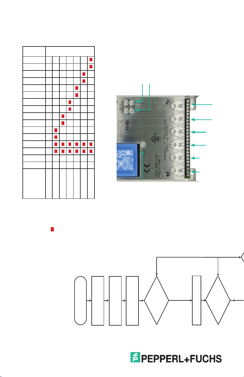
Description
Fault LEDs
Input 6b LED
Input 6a LED
Input 5b LED
Input 5a LED
Input 4b LED
Input 4a LED
Input 3b LED
Input 3a LED
Input 2b LED
Input 2a LED
Input 1b LED
Input 1a LED
SR2 Red LED
SR1 Red LED
SR2 Grn LED
SR1 Grn LED
p p
All guards closed
Green LED
p
Only input 1 open
Red LED
Only input 2 open
Only input 3 open
Only input 4 open
Only input 5 open
momentarily at power up
O at all times other than
Only input 6 open
SR1, SR2 LEDs
Red relay status
Red fault LED
Green relay status
5A, 5B 6A, 6B
3A, 3B 4A, 4B
1A, 1B 2A, 2B
Input
status
LEDs
Daily inspection
Power off
No
Yes
Reapply power
Wait 3 -5 seconds
switches are closed
Ensure that all door guard
LEDs on?
Are any red input
Verify all doors are closed
No
Yes
LEDs on?
Are any red input
8
Page 9

Door Interrupt System with FYQLA1-140R-3 Logic Amplier
the 50FY41 switch
Open or remove next
guard/door equipped with
No
Yes
been tested?
Have all inputs
Close open guard/door
Yes
LEDs lit?
Are the 2 red relay
No
Yes
Wait 3 -5 seconds
door lit?
Are only the 2 red
input LEDs for the open
No
Yes
Yes
LEDs lit?
Are the 2 green relay
No
the 50FY41 switch
Open or remove first
guard/door equipped with
Is the red fault LED
Document results in
No
lit or blinking?
inspection records
Done / Passed
Yes
Shut down machine &
contact repair technician
9
Page 10

Door Interrupt System with FYQLA1-140R-3 Logic Amplier
System inputs
The six device inputs allow the user to monitor up to six functional switch devices.
Each device must have two channels of output, one sourcing output and one
sinking output. These outputs must operate in tandem for a valid switch function
to be recognized by the FYQLA1-140R-3. If the output channels of the switches are
not functioning in a synchronized manner the amplier will not accept the switch
closure as a valid. The allowable timing between closure of switch channel A and
channel B is approximately one second. If any given pair of switch channels does
not transition to the proper state in the minimum time, then the monitor will issue a
fault on that switch channel and prevent the output from closing.
Reset faulted state
If an invalid door switch sequence is detected by the Channel A and Channel B
synchronization, the output safety relays will open and red fault LED will blink.
Reset is accomplished by a power down/power up sequence.
Actuator Switch
Channel A
Channel B
Monitor input
Channel A
Output relays to de-energize equipment
When an invalid input condition is recognized by the door interrupt
system, the output safety relay will be de-energized. This will cause the
relay contact pair to open. Be sure to verify the contact power ratings
Attention
when applying these relay outputs to energize/de-energize associated
equipment.
Hardware
Inputs
• Six switch inputs compatible with dual channel devices
▸ Pepperl+Fuchs’ 50FY41 series magnetic sensors
Channel B
Minimum time
between transitions
10
Page 11

Door Interrupt System with FYQLA1-140R-3 Logic Amplier
Indicators
The FYQLA1-140R-3 has indicators on front of the device for the following
functions:
• State of the connected input switches
▸ Two indicators per switch input (channel A & channel B)
▸ Indicator is illuminated (on) when the switch state is open
• Relay output status
▸ Two indicators available, one per relay state:
Red indicator illuminated when de-energized
Green indicator illuminated when energized
• Fault Indicator
▸ Fault indicator ashes under the following conditions:
Input switch sequence error (channel A and channel B timing)
▸ Output relay contact monitor fault
Indicator status table
Switch Status Relay 1 Status Relay 2 Status
1
2
2
2
Green LED ON
p
Red LED ON
Red
Channel
1 LED
Condition
Door
Sensor
Open
Door
Normal
Operation
Sensor
Closed
Door
Sensor
Fault
Relay 1
Welded
Contact
Fault
Faults
Relay 2
Welded
Contact
Fault
Internal
Relay
Fault
Power O
1) Indicator status changes to fault 1-2 seconds after input sequence fault is detected
2) Fault may require the next operational cycle to start before fault is indicated
Red
Channel
2 LED
Red
Open
LED
Green
Closed
Red
BLINKING
OFF
Red
Green
Open
LED
Closed
LED
p p
p
LED
p
OPEN
CLOSED
Red
Fault
LEDs
SR1
Contact
Status
11
Page 12

Door Interrupt System with FYQLA1-140R-3 Logic Amplier
Guided relays
The door interrupt system incorporates two force-guided safety relays that are
monitored for proper operation and generate a redundant output for application
use.
Input devices
Magnetic switches
The 50FY41 series hall eect door switches are a noncontact, magnetic actuation
system consisting of a sensor and a magnetically keyed actuator. The sensor
contains two hall-eect integrated circuits that are connected independently.
When exposed to this magnetic actuator and properly aligned, the sensor
responds with an output.
Approved devices
• 50FY41 series Hall eect door interrupt sensor
• 52FY31 series Keyed hall eect magnetic-actuator
NOTE: These are the only approved devices that should be used.
50FY41 sensor alignment
12
Attention
Cable length
Attention
Ensure the alignment of the sensor and magnetic actuator are correct
for proper operation. A 10 mm (0.39 in) separation distance between
sensor and actuator will cause an OFF condition, independent of axial
oset distance.
Sensor cable length must not exceed 25 m (80 ft).
Page 13

Door Interrupt System with FYQLA1-140R-3 Logic Amplier
Nominal oset distances
Sensing distance mm (in)
Oset Max. Actuator
O Distance
Distance
0 (zero) 2.5 (0.1) 10 (0.4)
3.8 (0.15) 1.3 (0.05) 10 (0.4)
7.5 (0.3) 0 (zero) 10 (0.4)
Offset
Hall effect sensor
Device dimensions
(for reference only—dimensions in mm)
39
25.4 12.7
39
25.4 12.7
Magnet actuator
Distance
25.4
39
2 x ø5
50FY41 hall eect sensor
Cable Length
25.4
39
52FY31 magnet actuator
2 x ø5
13
Page 14

Door Interrupt System with FYQLA1-140R-3 Logic Amplier
Note
Installation
Installation requirements
Panel mounted inside an enclosure using the four mounting feet in the stainless
steel housing. The FYQLA1-140R-3 is intended to be installed in a clean and dry
environment. A control cabinet must be used to guarantee that the unit is exposed to
no worse than an IP20 environment. The unit is designed to meet the requirements for
industrial environments. Suitability for other environments cannot be ensured.
Clearance around device
Adequate clearance should be provided around the device to allow for proper
cooling and ventilation of the control unit.
General safety notes
Installation and testing
After installation, the FYQLA1-140R-3 and all connected devices must be tested to
ensure proper wiring and operation. All wiring should be veried before applying
power to the unit. Once power is applied, each door switch should be opened to
verify proper operation of the system.
Periodic inspection and testing of the door interrupt system is
recommended. The device must be cycled and safety operation veried
once per day, or between equipment usage cycles. During this time,
proper operation of the safety switches and the correct response
of output safety relays must be veried. Inspection records of the
performed inspections must be maintained.
14
Page 15

Door Interrupt System with FYQLA1-140R-3 Logic Amplier
Warning
Warning
Warning
Electrical installation
Switch the main machine power OFF prior to installation!
The machine could inadvertently start during installation.
The door interrupt system fullls the EMC requirements in accordance
with EN/IEC 61326-3-2:2008 for safety related systems.
Powering the device
The FYQLA1-140R-3 is to be powered only with 120 VAC with
a supply tolerence of no greater than 15% and a frequency of
45-65 Hz.
All connected downstream devices and wiring/installation must
correspond to the required category according to
ISO 13849-1:2015.
Wiring requirements
• GREEN terminal block: Input supply power/Relay contact output
• BLACK terminals: CH1 ... CH 6, 50FY41 switch inputs
Improper installation
This product is designed to conform to the technical requirements of
ISO 13849-1:2015. To ensure compliance with these requirements,
50FY41 series sensors and 52FY31 series actuators MUST be used
with the FYQLA1-140R-3.
Consult with the local safety agency and its requirements when
designing a machine control system, interface, and all control
elements that aect safety. Strictly adhere to all installation
instructions. Failure to comply with these instructions could result in
death or serious injury.
15
Page 16

Door Interrupt System with FYQLA1-140R-3 Logic Amplier
Wiring diagram
16
FYQLA1-140R-3
Page 17

Door Interrupt System with FYQLA1-140R-3 Logic Amplier
Warning
Electrical connection
Monitor terminals 50FY41 Unused inputs
R (positive) RED - positive
W (normally open, sourcing) WHITE - output
B (negative) BLACK - ground
O (normally open, sinking) ORANGE - output
Use two, 22 K
resistors
(included)
50FY41
Red
White
Black
Orange
x1
R
x2
W
x3
B
x4
O
If less than six sensors are connected to the safety monitor, install two, 22 K
resistors (one between R-W and one between B-O) into the unused inputs.
R W B O
Do not connect or remove wires with power applied.
17
Page 18

Door Interrupt System with FYQLA1-140R-3 Logic Amplier
Warning
Warning
Commissioning and startup
Do not commission without a check by qualied safety personnel!
The door interrupt system must be installed by qualied personnel
who are properly trained in the installation, application, and usage of
the FYQLA1-140R-3 product.
You must ensure that no one is located in the hazardous area before
commissioning!
Check the hazardous area and secure it so that people cannot enter.
For example, set up warning signs, attach blocking ropes or similar.
Observe the relevant laws and local regulations.
Validation of the application
You may commission the system only if all pretests were successful. Validation may
be performed only by qualied personnel. The general acceptance comprises the
following tests:
• Check whether the components used correspond to the required Performance
Level in accordance with EN ISO 13849-1:2015.
• Check that the devices connected to the door interrupt system are in
accordance with this user manual.
• Clearly mark all connection cables and plugs.
• Perform a complete verication of the safety functions of the system in each
operating mode and error simulation. Observe the response times of the
system in response to tested functions.
18
Page 19

Door Interrupt System with FYQLA1-140R-3 Logic Amplier
Diagnostics
Faults
The door interrupt system has multiple LEDs mounted on the top of the device to
provide diagnostic and troubleshooting assistance. LEDs are provided for each
switch input pair, indicating the status of the individual channel. Also provided are
output LEDs indicating the status of each of the safety relays. In addition, a fault
LED provides indication of when an input switch error has occurred, resulting in a
fault condition and opening of the safety relay. Fault conditions can be cleared only
upon power down-power up, of the door interrupt system.
Technical support
Troubleshooting
Problem Probable cause Remedy
No supply power Verify incoming power is present
No LEDs illuminated
Fault LED is ashing
and single LED is lit
for a sensor input
while actuated or
de-actuated
Blown internal fuse
Misaligned sensor and
actuator
Input screw terminal loose Fully install screw terminal
Defective sensor
Internal failure in door switch
monitor
Verify input power is within spec,
and then replace fuse
Check alignment and realign as
needed
See Fault diagnosis (next page)
to help determine problems
All inputs activated
(all input LEDs are o)
and the relays do not
activate
Defective unit Replace unit
19
Page 20

Door Interrupt System with FYQLA1-140R-3 Logic Amplier
Fault diagnosis
If fault LED ashes and no sensor alignment problem can be found:
• Turn o power
• Unwire sensors from input terminals
• Power up unit
•
If fault LED begins to ash repeatedly after 2-3 seconds, the system needs to be
replaced. If the fault LEDs do not begin to ash:
• Remove power, then wire one sensor (R,W,B,O) connection at a time. Apply
power, waiting 2-3 seconds. Repeat sequence with all sensors until fault
LED begins to ash. This will be the sensor/actuator that is generating
the fault condition. Reevaluate alignment and terminal connections. If no
problem is found, replace the sensor and/or actuator in question
Approvals
UL508
Product specications
Input specications
FYQLA1-140R-3 120 VAC ± 15% <0.25A @ 45 to 65 Hz
Input devices (6) dedicated noncontact hall eect door
Switch voltage input 12 VDC (2 channel, sink/source)
Typical response time 20 ms (switch open to contact open)
Power up time 3 s
Output specications
Contact material AgCuNi + 0.2 um Au
Continuous current 5 mA to 5 A (N.O. contact)
Relay type 1 relay output, force guided connection,
Inrush current (max) 30 A for 20 ms
Maximum switching
characteristics
(Determined acc. to
EN60947-4-1/EN60947-5-1)
External fusing should be added
to protect the application and unit
from unforseen circumstances
sensors (50FY41 series)
normally open contacts
AC-1: 250 V/5 A (100,000 cycles)
AC-15: 230 V/3 A (150,000 cycles)
DC-1: 24 V/5 A (100,000 cycles)
DC-13: 24 V/1 A /0.1 Hz (100,000 cycles)
20
Page 21

Door Interrupt System with FYQLA1-140R-3 Logic Amplier
Product specications (cont.)
Functional safety related parameters*
Safety function
Safe state
Standards/regulations ISO 13849-1 :2015/UL 508
Performance level acc. to ISO 13849-1 PL d
Structure acc. to ISO 13849-1 Category 3
MTTFd (years)
DC
d
PFH 2.06 x 10E
CCF
TM (years)
Pollution degree
Over-voltage category
Rated insulation voltage 250 V
Protection degree IP20, Class 1 “indoor use only”
Housing material 304 stainless steel
Internal hardware diagnostic fault
detection
Relay output closed only when sensors activated by
appropriate target
Relay output open
75850
98.6 %
-7
5 %
20
2
(OC) II
< 4 s
*The following assumptions were made during the failure modes, eects, and diagnostic analysis (FMEDA) of the
FYQLA1-140R-3:
• Failure rates are constant, wear out mechanisms are not included.
• Failure rates are based on the Siemens standard SN29500.
• Power supply failures are not included in the FMEDA, a loss of power introduces the safe state.
• It was assumed that the appearance of a safe error (e. g., output in safe state) would be repaired within 8
hours (e. g., remove sensor burnout).
• During the absence of the device for repairing, measures have to be taken to ensure the safety function (for
example: substitution by an equivalent device).
• The stress levels are average for an industrial environment and can be compared to the Ground Fixed
Classication of MIL-HDBK-217F. Alternatively, the assumed environment is similar to IEC 60654-1 Class C
(sheltered location) with temperature limits within the manufacturer’s rating and an average temperature over
a long period of time of 40 °C. Humidity levels are assumed within manufacturer’s rating. For a higher average
temperature of 60 °C, the failure rates should be multiplied with an experience based factor of 2.5. A similar
multiplier should be used if frequent temperature uctuation must be assumed.
21
Page 22

Door Interrupt System with FYQLA1-140R-3 Logic Amplier
Product specications (cont.)
Ambient conditions
Operating temperature -25 °C to +70 °C noncondensing
Storage temperature -25 °C to +70 °C noncondensing
Terminal block - power and relays
Conductor cross section capacity 0.2 mm² to 2.5 mm² (22 to 14 AWG) Cu
Tightening torque 0.5 Nm (4.5 lb-in)
Strip length 7 mm
Connection method Terminal block - screw connection
Terminal block - sensor inputs
Conductor cross section capacity 0.5 mm² to 2.5 mm² (22 to 14 AWG) Cu
Tightening torque 0.5 to 0.6 Nm (4.5 to 5.3 lb-in)
Strip length 6 mm
Connection method Terminal block - screw connection
General data
Dimensions - FYQLA1-140R-3 203.0 mm H x 135.0 mm W x 58.0 mm D
Mechanical service life (approx.) > 1,000,000 operations
Indicators
Sensor status
Relay status
Fault status
LED red, one per channel / two per input
LED green (2), red (2)
LED red, ashing
(See indicator status table, pg 11, for indication
denitions)
22
Page 23

Door Interrupt System with FYQLA1-140R-3 Logic Amplier
Dimensions
(for reference only—dimensions in mm)
4X Ø 5.56
L2
R1 R1
L1
V
120
1/8 A SLOW BLOW
250 VAC
203
1/8A
190
5A 250VAC
!
Twinsburg, Ohio 44087
Phone: (330)425–3555
.630 A 250 VAC
RELAY
CONDITION
CLOSED
OPEN
37
58
LOGIC AMPLIFIER
FYQLA1-140R-3
DISCONNECT 22K RESISTORS WHEN
1
2
R W B 0
R W B 0
LISTED
IND. CONT. EQ.
1EA5
CONNECTING SENSORS
3
R W B 04R W B 05R W B 06R W B 0
108
135
23
Page 24

North/Central American Headquarters
Pepperl+Fuchs Inc.
Twinsburg · Ohio · USA
Tel. +1 330 486 0002
E-Mail: fa-info@us.pepperl-fuchs.com
Subject to modifications • Copyright Pepperl+Fuchs • Printed in USA • TDOCT-B1Z0_ENG 09/18
 Loading...