

Multiturn absolute encoder FVM58
Model Number
FVM58
Features
• Industrial standard
housing Ø58 mm
•25-bit multiturn
• Output code: gray and binary
• Short-circuit proof push-pull output
• Inputs for selecting counting direction, LATCH, and PRESET
• Code change frequency up to 400
kHz
• Servo or clamping flange
Description
The emphasis for this series is on rapid data transfer. Position data are read directly out of the Gray
code disc. The high code switching frequency of
400 kHz is achieved by consciously avoiding the
use of a microcontroller.
In terms of the mechanics, designs with clamping
flange or servo flange are available for the FVM58
multiturn absolute encoder.
Release date: 2014-04-15 10:12 Date of issue: 2016-01-26 t25462_eng.xml
Refer to “General Notes Relating to Pepperl+Fuchs Product Information”.
Technical data
Functional safety related parameters
MTTFd 110 a
Mission Time (T
L
1.9 E+11 at 6000 rpm and 20/40 N axial/radial shaft load
10h
Diagnostic Coverage (DC) 0 %
Electrical specifications
Operating voltage U
No-load supply current I
Power consumption P
Linearity ± 0.5 LSB
Output code Gray code, binary code
Code course (counting direction) cw ascending (clockwise rotation, code course ascending)
Code preparation time 0.3 ms
Interface
Interface type Push-pull, parallel , short-circuit protected
Resolution
Multiturn 25 Bit
Load current 20 mA
Voltage drop ≤ 2.5 V
Signal voltage
High operating voltage minus voltage drop
Low ≤ 2.8 V
Rise time 300 ns
De-energized delay 300 ns
Code change frequency 400 kHz
Input 1
Input type Selection of counting direction (cw/ccw)
Signal voltage
High 10 ... 30 V
Low 0 ... 2 V
Input current < 6 mA
Signal duration ≥ 10 ms
Input 2
Input type Temporary storage (LATCH)
Signal voltage
High 10 ... 30 V
Low 0 ... 2 V
Input current < 6 mA
Signal duration ≥ 100 µs
Switch-on delay < 0.1 ms
Switch-off delay < 0.1 ms
Input 3
Input type zero-set (PRESET)
Signal voltage
High 10 ... 30 V
Low 0 ... 2 V
Input current < 6 mA
Signal duration ≥ 10 ms
Switch-on delay < 1 ms
Connection
Connector type 9426, 26-pin
Cable Ø9 mm, 15 x 2 x 0.14 mm2, 2 m
Standard conformity
Degree of protection DIN EN 60529, IP65
Climatic testing DIN EN 60068-2-3, no moisture condensation
Emitted interference EN 61000-6-4:2007
Noise immunity EN 61000-6-2:2005
Shock resistance DIN EN 60068-2-27, 100 g, 6 ms
Vibration resistance DIN EN 60068-2-6, 10 g, 10 ... 2000 Hz
Ambient conditions
Operating temperature -40 ... 85 °C (-40 ... 185 °F)
Storage temperature -40 ... 85 °C (-40 ... 185 °F) (cable models: -5 ... 70 °C)
Mechanical specifications
Material
Combination 1 housing: powder coated aluminum
Combination 2 (Inox) housing: stainless steel
Mass approx. 400 g (combination 1)
Rotational speed max. 12000 min
Moment of inertia 30 gcm
Starting torque ≤ 5 Ncm
Shaft load
Axial 40 N
Radial 110 N
) 20 a
M
B
0
0
10 ... 30 V DC
max. 140 mA
≤ 2.5 W , without output drivers
cable models:
-30 ... 70 °C (rigid wiring)
-5 ... 70 °C (flexible wiring)
flange: aluminum
shaft: stainless steel
flange: stainless steel
shaft: stainless steel
approx. 800 g (combination 2)
-1
2
1
Multiturn absolute encoder FVM58
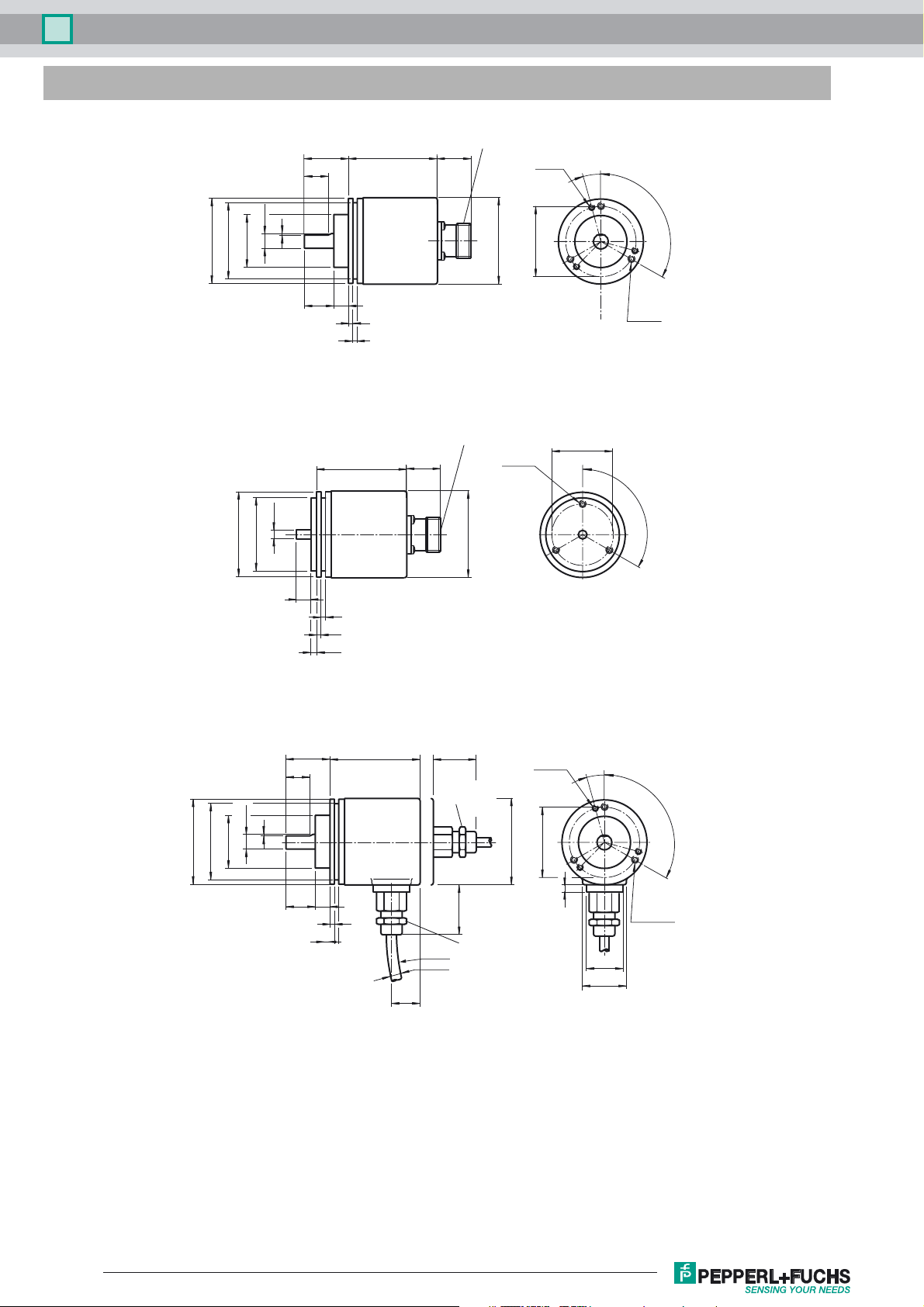
Dimensions
ø53
ø58
ø36f7
Clamping flange
ø58
ø50f7
ø10h8
ø6h7
1
30 62
18
20 10
3
3
62
Connector, axial
~28
** Aluminium: d = 59, stainless steel: d = 61
Connector, axial
~28
d**
d**
3 x M4
6 deep
3 x M3
6 deep
ø48
ø42
15˚
3 x 120˚
3 x M4
6 deep
3 x 120˚
Servo flange
1
ø10h8
ø53
ø58
ø36f7
Clamping flange
10
30
18
20 10
3
3
4
3
3
** Aluminium: d = 59, stainless steel: d = 61
62
~18
~28
Cable gland
PG9, axial
~33
Cable gland
R100
ø9
radial
PG9,
** Aluminium: d = 59, stainless steel: d = 61
d**
3 x M3
6 deep
ø48
15˚
3 x 120˚
5
25
30
3 x M4
6 deep
Release date: 2014-04-15 10:12 Date of issue: 2016-01-26 t25462_eng.xml
Refer to “General Notes Relating to Pepperl+Fuchs Product Information”.
2

Multiturn absolute encoder FVM58
ø42
3 x 120˚
5
25
30
ø6h7
ø58
ø50f7
Servo flange
~28
62
Cable gland
PG9, axial
d**
10
3
3
4
~18
~33
Cable gland
R100
ø9
radial
PG9,
** Aluminium: d = 59, stainless steel: d = 61
3 x M4
6 deep
Electrical connection
Signal Cable Ø9 mm, 30-core Connector 9426, 26-pin Explanation
GND (rotary encoder) White 1 Power supply
(rotary encoder) Brown 2 Power supply
U
b
Bit 1 Green 3 Data output
Bit 2 Yellow 4 Data output
Bit 3 Grey 5 Data output
Bit 4 Pink 6 Data output
Bit 5 Blue 7 Data output
Bit 6 Red 8 Data output
Bit 7 Black 9 Data output
Bit 8 Violet 10 Data output
Bit 9 Grey/Pink 11 Data output
Bit 10 Red/Blue 12 Data output
Bit 11 White/Green 13 Data output
Bit 12 Brown/Green 14 Data output
Bit 13 White/Yellow 15 Data output
Bit 14 Yellow/Brown 16 Data output
Bit 15 White/Grey 17 Data output
Bit 16 Grey/Brown 18 Data output
Bit 17 White/Pink 19 Data output
Bit 18 Pink/Brown 20 Data output
Bit 19 White/Blue 21 Data output
Bit 20 Brown/Blue 22 Data output
Bit 21 White/Red 23 Data output
Bit 22 Brown/Red - Data output
Bit 23 White/Black - Data output
Bit 24 Brown/Black - Data output
Bit 25 Pink/Green - Data output
V/R Grey/Green 25 Input for selection of counting direction
Latch Yellow/Grey 24 Temporary storage input
PRESET Yellow/Pink 26 Zero setting
19 6
4 5
18
17 3
2
16
1
15
25
14
24
13 23
26
7
20
8
9
21
12
11
22
10
Release date: 2014-04-15 10:12 Date of issue: 2016-01-26 t25462_eng.xml
Refer to “General Notes Relating to Pepperl+Fuchs Product Information”.
3

Multiturn absolute encoder FVM58
Inputs
Input for temporary storage (LATCH)
Input zero setting (PRESET)
IN
Filter
U
e
⊥
Pull down
Logic
Input level: "0"
"1" 10 V ... 30 V,
Ie < 6 mA
0 V ... 2 V,
Input for selection of counting direction (V/R)
IN
U
e
⊥
Pull up
Filter
Logic
Input for selection of counting direction (V/R)
The counting direction for the absolute value rotary encoder as seen looking on the shaft is defined as right rotating (cw) rising or descending. The counting
direction can be reversed with the V/R input. If the input is not used, the counting direction is defined as rising (standard), the level is at "1". Pulse duration
T > 10 ms.
Input level: "1" or unused = rising code value with direction of rotation cw.
Input level: "0" = descending code value for direction of rotation cw.
Input for temporary storage (LATCH)
With LATCH input "active", the position data on the parallel interface are "frozen". This makes it possible to accept position data without errors (especially
for binary position data), since any change in the data during the read procedure is prevented. If this input is unused, its value is "0". Pulse duration T > 100
µs.
Input level: "1" = position data saved and stable at the output.
Input level: "0" or unused = position data free running at the output.
Input zero setting (PRESET)
By means of the PRESET input, the absolute value rotary encoder can be adjusted electronically to position value 0. Pulse duration T > 10 ms.
Input level: "0" or unused = inactive.
Input level: "1" = Data output word is set to 0.
Release date: 2014-04-15 10:12 Date of issue: 2016-01-26 t25462_eng.xml
Refer to “General Notes Relating to Pepperl+Fuchs Product Information”.
4

Multiturn absolute encoder FVM58
Accessories
For type Accessories Name/defining feature Order code
D1: Ø10 mm, D2: Ø10 mm 9401
Couplings
Measurement wheels with circumference of 500 mm
FVM58N-011
Measurement wheels with circumference of 200 mm
Mounting aids
Couplings
FVM58N-032
Mounting aids
All Connector Cable socket 9426
For additional information on the accessories, please see the "Accessories" section.
D1: Ø10 mm, D2: Ø10 mm 9404
D1: Ø10 mm, D2: Ø10 mm 9409
D1: Ø10 mm, D2: Ø10 mm KW
Plastic 9101, 10
Pimpled rubber 9102, 10
Knurled aluminium 9103, 10
Knurled plastic 9112, 10
Plastic 9108, 10
Pimpled rubber 9109, 10
Knurled aluminium 9110, 10
Knurled plastic 9113, 10
Mounting bracket 9203
Mounting bracket 9213
D1: Ø6 mm, D2: Ø6 mm 9401
D1: Ø6 mm, D2: Ø6 mm 9402
D1: Ø6 mm, D2: Ø6 mm 9404
D1: Ø6 mm, D2: Ø6 mm 9409
2D1: Ø6 mm, D2: Ø6 mm KW
Mounting bracket and set 9300 and 9311-3
Eccentric clamping elements 9310-3
Release date: 2014-04-15 10:12 Date of issue: 2016-01-26 t25462_eng.xml
Refer to “General Notes Relating to Pepperl+Fuchs Product Information”.
5

Multiturn absolute encoder FVM58
Order code
FVM58 – 3 N–
Shaft version
V
Data format
Fast parallel
F
Number of bits singleturn
(Resolution)
8192
13
Number of bits multiturn
*)
(Revolutions)
4096 (only connection type K2)
12
256
08
Temperature range
Not expanded
N
Output code
Binary
B
Gray
G
Option 1
V/R, LATCH, PRESET
3
Exit position
Axial
A
Radial
R
Connection type
Cable Ø9 mm, 15 x 2 x 0.14 mm²
K2
Plug connector type 9426, 26-pin (only axial)
AE
, 2 m
Shaft dimension/flange version
Shaft Ø10 mm x 20 mm with clamping flange
011
Shaft Ø6 mm x 10 mm with servo flange
032
Housing material
Aluminium, powder coated
N
Inox
I
Principle of operation
Multiturn
M
*) total number of bits (singleturn + multiturn) = 25 bit (cable version)
Solid shaft total number of bits (singleturn + multiturn) = 21 bit (plug connector version)
*)
Release date: 2014-04-15 10:12 Date of issue: 2016-01-26 t25462_eng.xml
Refer to “General Notes Relating to Pepperl+Fuchs Product Information”.
6
 Loading...