

Page 1
FABRIKAUTOMATION
MANUAL
VB24
BARCODE SCANNER
Page 2

VB24
ii
CONTENTS
REFERENCES ............................................................................................................. v
Conventions .................................................................................................................. v
Reference Documentation ............................................................................................ v
Services and Support .................................................................................................... v
SAFETY AND COMPLIANCE NOTICES .................................................................... vi
Laser Safety ................................................................................................................. vi
FCC Compliance .......................................................................................................... vii
Power Supply ............................................................................................................... vii
CE Compliance ............................................................................................................ vii
Handling ...................................................................................................................... viii
GENERAL VIEW .......................................................................................................... x
1 RAPID CONFIGURATION ........................................................................................... 1
Step 1 – Connect the System ........................................................................................ 1
Step 2 – Mount and Position the Scanner ..................................................................... 4
Step 4 – Mode Configuration ......................................................................................... 6
Step 5 – Install Genius™ Configuration Program ........................................................ 10
Step 6 – Test Mode ..................................................................................................... 15
Advanced Scanner Configuration ............................................................................... 16
2 INTRODUCTION ........................................................................................................ 17
2.1 Product Description ..................................................................................................... 17
2.1.1 Indicators .................................................................................................................... 18
2.2 ID-NET™ .................................................................................................................... 18
2.2.1 How To Setup/Configure the Scanner Network ........................................................... 20
2.3 Human Machine Interface ........................................................................................... 21
2.3.1 Diagnostic Indication ................................................................................................... 21
2.3.2 Mode Functions .......................................................................................................... 22
2.4 Display ........................................................................................................................ 24
2.4.1 Display Messages ....................................................................................................... 25
3 INSTALLATION ......................................................................................................... 28
3.1 Package Co
3.2 Mechanical Installation ................................................................................................ 29
3.3 Positioning .................................................................................................................. 33
4 CBX ELECTRICAL CONNECTIONS ......................................................................... 35
4.1 Power Supply .............................................................................................................. 36
4.2 Main Serial Interface ................................................................................................... 37
4.2.1 RS232 Interface .......................................................................................................... 38
4.2.2 RS485 Full-Duplex Interface ....................................................................................... 39
ntents ....................................................................................................... 28
Page 3

VB24
iii
4.2.3 RS485 Half-Duplex Interface ...................................................................................... 40
4.3 ID-NET™ Interface ...................................................................................................... 42
4.3.1 ID-NET™ Cables ........................................................................................................ 42
4.3.2 ID-NET™ Response Time .......................................................................................... 43
4.3.3 ID-NET™ Network Termination .................................................................................. 47
4.4 Auxiliary RS232 Interface ............................................................................................ 47
4.5 Inputs .......................................................................................................................... 48
4.5.1 Code Verifier ............................................................................................................... 51
4.6 Outputs ....................................................................................................................... 51
4.7 User Interface - Host ................................................................................................... 53
5 25-PIN CABLE ELECTRICAL CONNECTIONS ........................................................ 54
5.1 Power Supply .............................................................................................................. 55
5.2 Main Serial Interface ................................................................................................... 55
5.2.1 RS232 Interface .......................................................................................................... 56
5.2.2 RS485 Full-Duplex Interface ....................................................................................... 57
5.2.3 RS485 Half-Duplex Interface ...................................................................................... 58
5.3 ID-NET™ Interface ...................................................................................................... 60
5.3.1 ID-NET™ Cables ........................................................................................................ 60
5.3.2 ID-NET™ Response Time .......................................................................................... 61
5.3.3 ID-NET™ Network Termination .................................................................................. 65
5.4 Auxiliary RS232 Interface ............................................................................................ 65
5.5 Inputs .......................................................................................................................... 66
5.5.1 Code Verifier ............................................................................................................... 69
5.6 Outputs ....................................................................................................................... 69
5.7 User Interface - Host ................................................................................................... 70
6 TYPICAL LAYOUTS ................................................................................................... 72
6.1 Point-to-Point .............................................................................................................. 72
6.2 Pass-Through ............................................................................................................. 74
6.3 ID-NET™ .................................................................................................................... 76
6.4 RS232 Master/Slave ................................................................................................... 79
6.5 Multiplexer Layout ....................................................................................................... 80
7 READING FEATURES ............................................................................................... 81
7.1 Advanced Code Reconstruction (ACR™ 4) ................................................................ 81
7.1.1 Tilt Angle for Advanced Code Reconstruction ............................................................. 82
7.1.2 Advanced Code Reconstruction Reading Conditions ................................................. 83
7.2 Linear Code Reading .................................................................................................. 85
7.2.1 Step-Ladder Mode ...................................................................................................... 85
7.2.2 Picket-Fence Mode ..................................................................................................... 86
7.3 Performance ............................................................................................................... 87
7.4 Reading Diagrams ...................................................................................................... 88
Page 4

VB24
iv
8 MAINTENANCE ......................................................................................................... 91
8.1 Cleaning ...................................................................................................................... 91
9 TROUBLESHOOTING ............................................................................................... 92
9.1 General Guidelines ..................................................................................................... 92
10 TECHNICAL FEATURES ........................................................................................... 95
GLOSSARY ................................................................................................................ 97
INDEX ....................................................................................................................... 101
Page 5

VB24
v
REFERENCES
CONVENTIONS
This manual uses the following conventions:
“User” or “Operator” refers to anyone using a VB24.
“Device” refers to the VB24.
“You” refers to the System Administrator or Technical Support person using this manual to
install, mount, operate, maintain or troubleshoot a VB24.
REFERENCE DOCUMENTATION
The documentation related to the VB24 management is listed below:
• CBX100 Installation Manual
• CBX500 Installation Manual
• CBX Accessory Manuals
SERVICES AND SUPPORT
Pepperl+Fuchs GmbH provides several services as well as technical support through its
website. Log on to www.pepperl-fuchs.com.
• PRODUCTS
Search through the links to arrive at your product page which describes specific Info,
Features, Applications, Models, Accessories, and Downloads including the Genius™
utility program, which allows device configuration using a PC. It provides RS232 and
Ethernet interface configuration.
• SERVICE
- Overview - Warranty Extensions and Maintenance Agreements
- Sales Network- Listing of Subsidiaries, Repair Centers, Partners
- Helpdesk
- Material Return Authorization
Page 6
VB24
vi
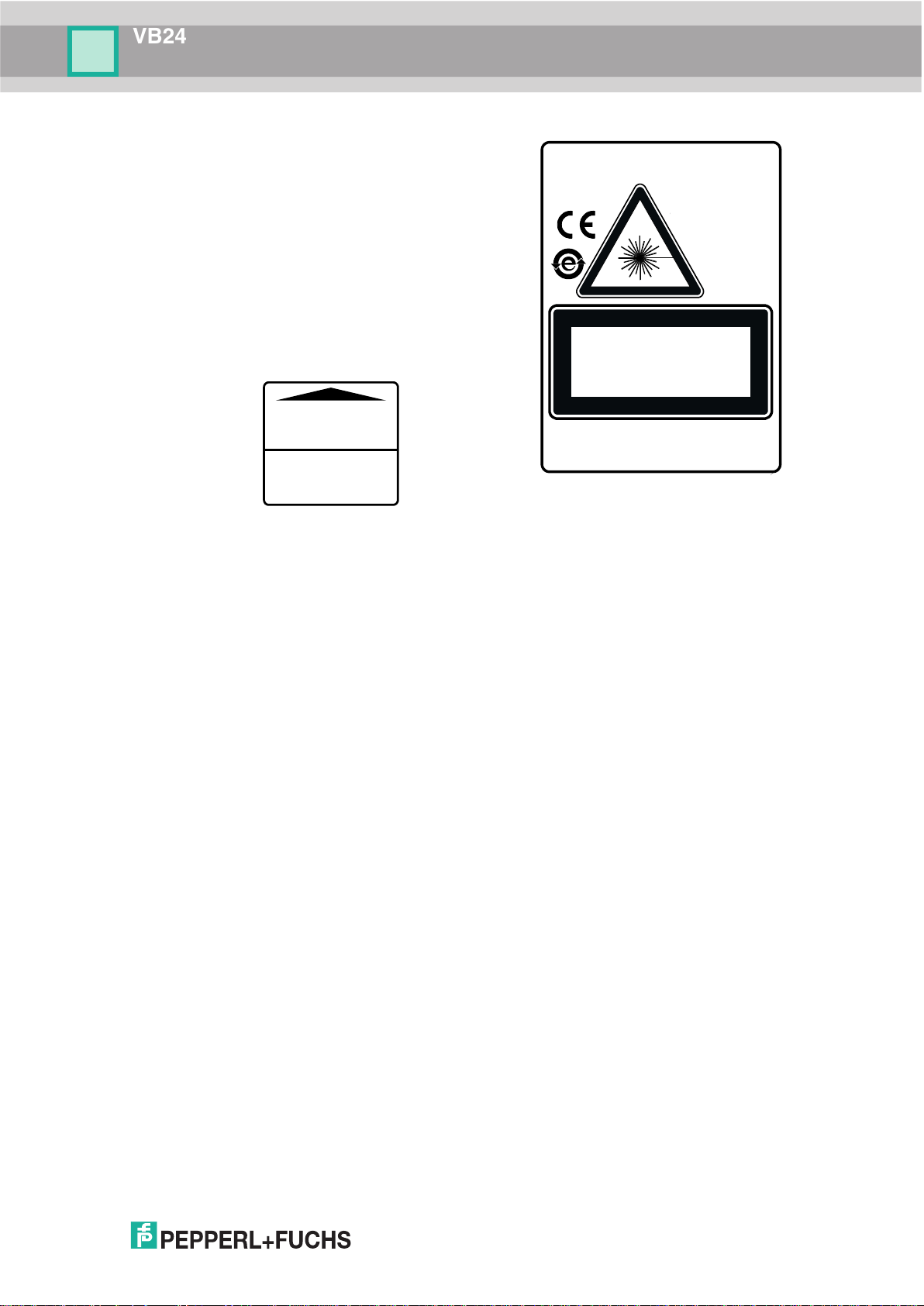
SAFETY AND COMPLIANCE NOTICES
LASER SAFETY
The following information is provided to comply with the rules imposed by international
authorities and refers to the correct use of the VB24 scanner.
Standard Regulations
This scanner utilizes a low-power laser diode. Although staring directly at the laser beam
momentarily causes no known biological damage, avoid staring at the beam as one would
with any very strong light source, such as the sun. Avoid that the laser beam hits the eye of an
observer, even through reflective surfaces such as mirrors, etc.
This product conforms to the applicable requirements of both EN 60825-1 and CDRH 21 CFR
1040 at the date of manufacture. The scanner is classified as a Class 2 laser product
according to EN 60825-1 regulations and as a Class II laser product according to CDRH
regulations.
There is a safety device, which allows the laser to be switched on only if the motor is rotating
above the threshold for its correct scanning speed.
The laser beam can be switched off through a software command.
Use of controls or adjustments or performance of procedures other than
WARNING
The laser light is visible to the human eye and is emitted from the window on the front of the
scanner (Figure A
Warning labels indicating exposure to laser light and the device classification are applied onto
the body of the scanner.
those specified herein may result in exposure to hazardous visible laser light.
, 5).
Page 7
VB24
vii
Disconnect the power supply when opening the
device during maintenance or installation to avoid
exposure to hazardous laser light.
The laser diode used in this device is classified as
a class 3B laser product according to EN 60825-1
regulations and as a Class IIIb laser product
according to CDRH regulations.
Any violation of the optic parts in particular can
cause radiation up to the maximum level of the
laser diode (40 mW at
AVOID EXPOSURE
LASER LIGHT IS EMITTED
FROM THIS APERTURE
CAUTION-CLASS 3B
LASER LIGHT WHEN OPEN
AVOID EXPOSURE TO BEAM
Complies with 21 CFR 1040.10
except for deviations pursuant
to Laser Notice N°50,
date June 24,2007
LASER LIGHT
DO NOT STARE INTO BEAM
CLASS 2 LASER PRODUCT
MAX. OUTPUT RADIATION 1 mW
EMITTED WAVE LENGTH 630~680 nm
IEC 60825-1:2007
U.S. pat. 5,992,740; 6,394,352B1; 6,742,710B2; 6,688,524B1.
Eu pat. 789,315B1; 959,426B9; 1,096,416 B1.
Jp pat.: JP 4,376,353
Warning and Device Class Labels
630 to 680 nm).
FCC COMPLIANCE
Modifications or changes to this equipment without the expressed written approval of
Pepperl+Fuchs GmbH could void the authority to use the equipment.
This device complies with PART 15 of the FCC Rules. Operation is subject to the following two
conditions: (1) This device may not cause harmful interference, and (2) this device must
accept any interference received, including interference which may cause undesired
operation.
This equipment has been tested and found to comply with the limits for a Class A digital
device, pursuant to part 15 of the FCC Rules. These limits are designed to provide reasonable
protection against harmful interference when the equipment is operated in a commercial
environment. This equipment generates, uses, and can radiate radio frequency energy and, if
not installed and used in accordance with the instruction manual, may cause harmful
interference to radio communications. Operation of this equipment in a residential area is likely
to cause harmful interference in which case the user will be required to correct the interference
at his own expense.
POWER SUPPLY
This product is intended to be installed by Qualified Personnel only.
This accessory device is intended to be supplied by a UL Listed or CSA Certified Power Unit
with «Class 2» or LPS power source, which supplies power directly to the scanner via the 25pin connector.
CE COMPLIANCE
Warning:
This is a Class A product. In a domestic environment this product may cause radio
interference in which case the user may be required to take adequate measures.
Page 8
VB24
viii
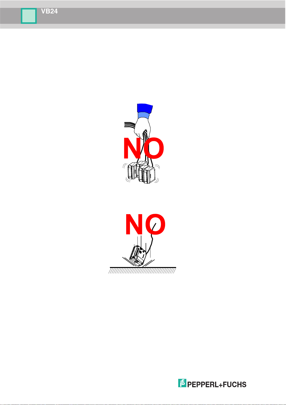
HANDLING
The VB24 is designed to be used in an industrial environment and is built to withstand
vibration and shock when correctly installed, however it is also a precision product and
therefore before and during installation it must be handled correctly to avoid damage.
• avoid that the scanners hit one another causing damage. They should be handled
separately.
• avoid that the scanners are dropped (exceeding shock limits).
Page 9

VB24
ix
• do not fine tune the positioning by striking the scanner or bracket.
• do not weld the scanner into position which can cause electrostatic, heat or output window
damage.
• do not spray paint near the scanner which can cause output window damage.
Page 10
VB24
x
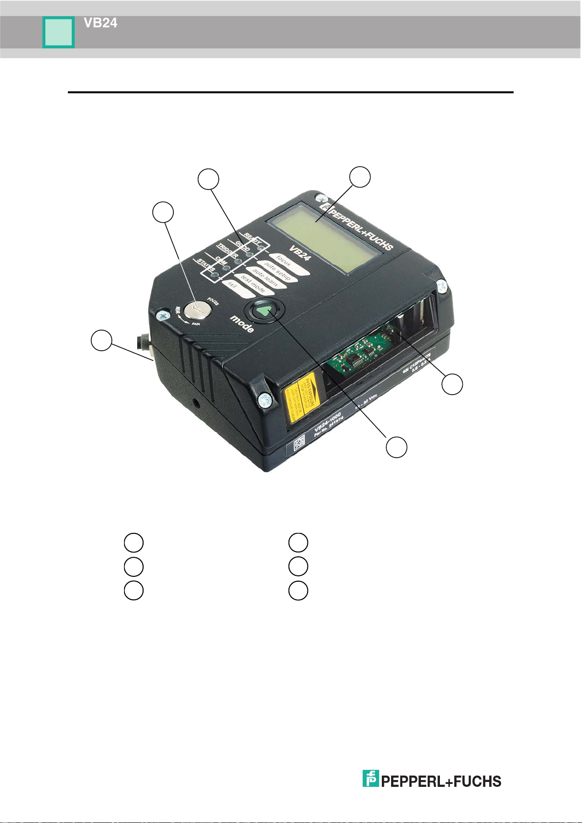
1
2
3
6
5
"POWER ON" LED
Indicator LEDs
Laser Beam Output Window
Push Button
4
Display
Focus Adjustment
4
2 1 3 5 6
GENERAL VIEW
VB24-1000
Figure A
Page 11
VB24
1
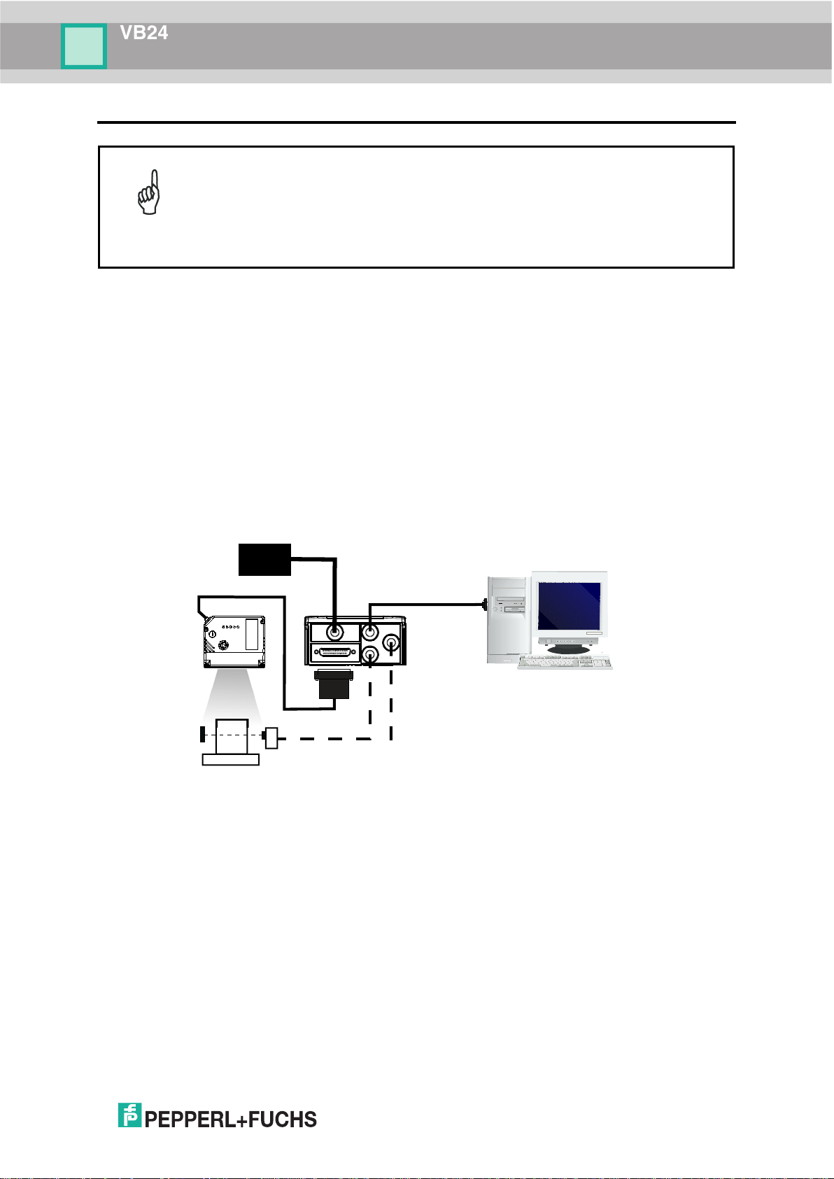
This chapter illustrates a Stand Alone application. For other types of
VB24
Host
Power
supply
*
* Presence Sensor
CBX100/500
I/O, AUX
MAIN
1 RAPID CONFIGURATION
installations, such as ID-NET™, Fieldbus, Pass-Through, Multiplexer Layout,
NOTE
etc., refer to chapters
the Genius™ configuration program, refer to the Context-Sensitive Help OnLine.
STEP 1 – CONNECT THE SYSTEM
To connect the system in a Stand Alone configuration, you need the hardware indicated in
Figure 1.
In this layout the data is transmitted to the Host on the main serial interface.
In Local Echo communication mode, the RS232 auxiliary interface can be used to transmit
data independently from the main interface selection.
When On-Line Operating mode is used, the scanner is activated by an External Trigger
(photoelectric sensor) when the object enters its reading zone.
4, 5 and 6. For complete scanner configuration using
P.S.
Figure 1 – VB24 in Stand Alone Layout
(for On-Line mode)
Page 12
VB24
2
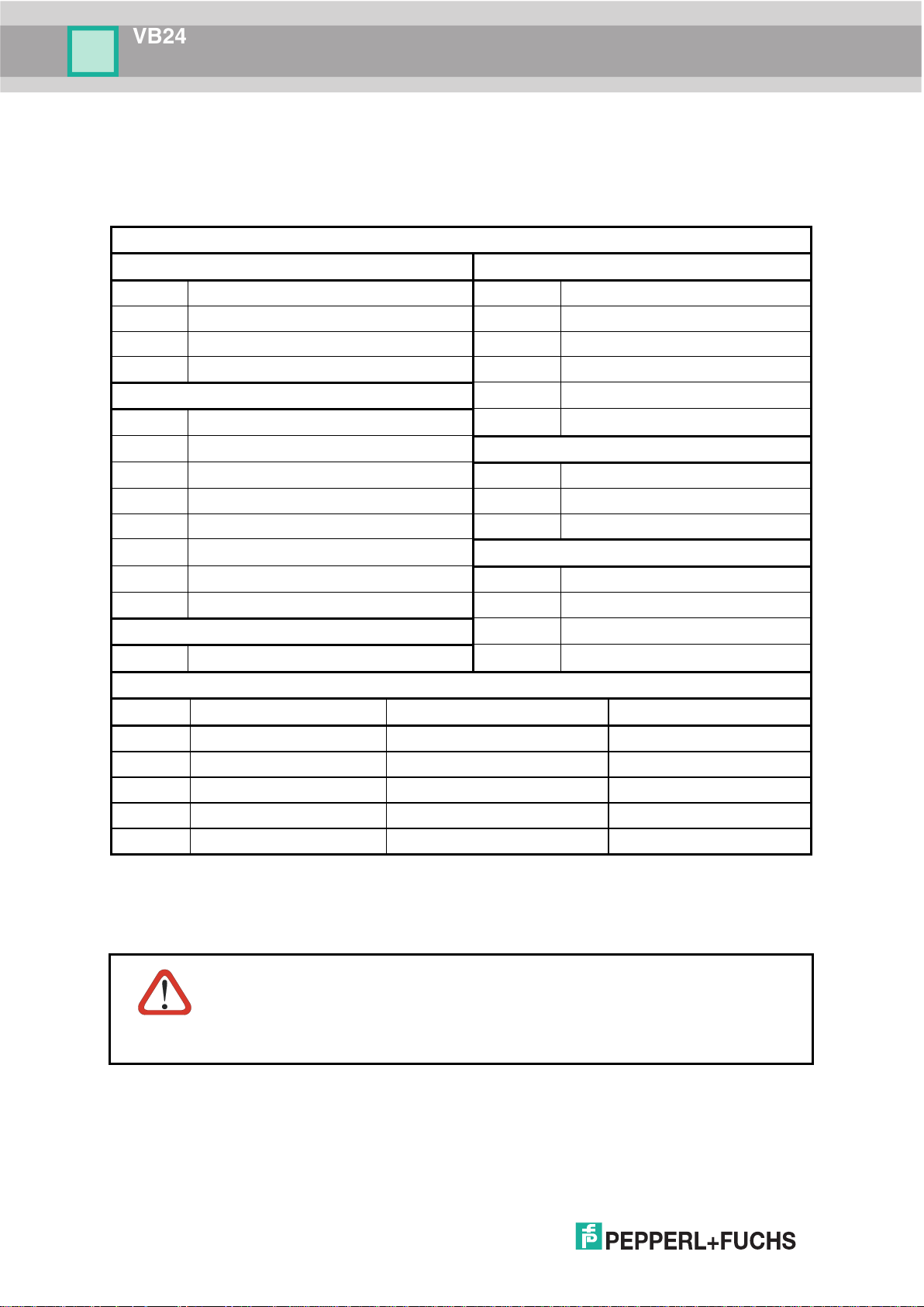
CBX100/500 Terminal Block Connectors
Input Power
Outputs
Vdc
Power Supply Input Voltage +
+V
Power Source - Outputs
GND
Power Supply Input Voltage -
-V
Power Reference - Outputs
Earth
Protection Earth Ground
O1+
Output 1 +
O1-
Output 1 -
Inputs
O2+
Output 2 +
+V
Power Source – External Trigger
O2-
Output 2 -
I1A
External Trigger A (polarity insensitive)
Auxiliary Interface
I1B
External Trigger B (polarity insensitive)
TX
Auxiliary Interface TX
-V
Power Reference – External Trigger
RX
Auxiliary Interface RX
+V
Power Source – Inputs
SGND
Auxiliary Interface Reference
I2A
Input 2 A (polarity insensitive)
ID-NET™
I2B
Input 2 B (polarity insensitive)
REF
Network Reference
-V
Power Reference – Inputs
ID+
ID-NET™ network +
Shield
ID-
ID-NET™ network -
Shield
Network Cable Shield
Main Interface
RS232
RS485 Full-Duplex
RS485 Half-Duplex
TX
TX+
RTX+
RTS
TX-
RTX-
RX
*RX+
CTS
*RX-
SGND
SGND
SGND
Do not connect GND, SGND and REF to different (external) ground
CBX100/500 Pinout for VB24
The table below gives the pinout of the CBX100/500 terminal block connectors. Use this
pinout when the VB24 reader is connected by means of the CBX100/500:
* Do not leave floating, see par. 4.2.2 for connection details.
references. GND, SGND and REF are internally connected through filtering
CAUTION
circuitry which can be permanently damaged if subjected to voltage drops
over 0.8 Vdc.
Page 13
VB24
3
13
25
14
1
25-pin D-sub male connector pinout
Pin
Name
Function
13, 9
Vdc
Power supply input voltage +
25, 7
GND
Power supply input voltage -
1
CHASSIS
Cable shield connected to chassis
18
I1A
External Trigger A (polarity insensitive)
19
I1B
External Trigger B (polarity insensitive)
6
I2A
Input 2 A (polarity insensitive)
10
I2B
Input 2 B (polarity insensitive)
8
O1+
Output 1 +
22
O1-
Output 1 -
11
O2+
Output 2 +
12
O2-
Output 2 -
20
RX
Auxiliary RS232 RX
21
TX
Auxiliary RS232 TX
23
ID+
ID-NET™ network +
24
ID-
ID-NET™ network -
14, 15, 16, 17
NC
Not Connected
RS485
Full-Duplex
RS485
Half-Duplex
2
TX
TX+
RTX+
3
RX
*RX+
4
RTS
TX-
RTX-
5
CTS
*RX-
25-pin Connector Pinout for VB24
The table below gives the pinout of the 25-pin male D-sub connector for connection to the
power supply and input/output signals. Use this pinout when the VB24 reader is connected by
means of the 25-pin connector:
Figure 2 - 25-pin Male D-sub Connector
Pin Name RS232
MAIN INTERFACE
(SW SELECTABLE)
* Do not leave floating, see par. 5.2.2 for connection details.
Page 14
VB24
4
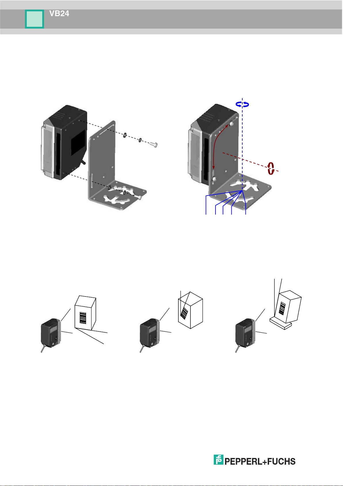
Skew
-45° -15° 0° 15° 45°
Pitch
S
T
P
STEP 2 – MOUNT AND POSITION THE SCANNER
VB24 Standard Models
1. To mount the VB24, use the mounting bracket to obtain the most suitable position for the
reader as shown in the figures below.
Figure 3 - Positioning with Mounting Bracket
2. When mounting the VB24 take into consideration these three ideal label position angles:
Skew 15° to 30°, Tilt 0° and Pitch 0°.
Assure at least 15° Minimize Minimize
3. Refer to the Reading Diagrams in par. 7.4 to decide the distance your scanner should be
Figure 4 –Skew, Tilt and Pitch Angles
positioned at.
Page 15
VB24
5
1. Power up the scanner. Wait for the power up sequence to finish. By default the scanner focus is in
n. The alternating message on the display shows the mechanical Focus
2. Using a screwdriver turn the focus adjustment screw in the desired direction, clockwise (focus nearer to
ocus position in centimeters and
See the Focus
READY
GOOD
TRIGGER
COM
STATUS
SETUP
LEARN
TEST
FOCUS
READY
GOOD
TRIGGER
COM
STATUS
SETUP
LEARN
TEST
FOCUS
READY
GOOD
TRIGGER
COM
STATUS
SETUP
LEARN
TEST
FOCUS
less than 30 cm
30 cm NEAR
32-38 cm
READY
GOOD
TRIGGER
COM
STATUS
SETUP
LEARN
TEST
FOCUS
READY
GOOD
TRIGGER
COM
STATUS
SETUP
LEARN
TEST
FOCUS
READY
GOOD
TRIGGER
COM
STATUS
SETUP
LEARN
TEST
FOCUS
40 cm MEDIUM
42-58 cm
60 cm FAR
READY
GOOD
TRIGGER
COM
STATUS
SETUP
LEARN
TEST
FOCUS
more than 60 cm
Step 3 – Focus the Scanner
The reading distance depends on the focus distance of the scanner and should be set
according to the application requirements. The Focus Position is set directly through the focus
adjustment screw on the front panel of the scanner. This screw moves the internal lens of the
scanner to change the focal length of the scanner. The setting is continuous but should not be
set beyond the limits "Too Far" or "Too Near" which appear on the display at the extremes of
the focus range. Although the scanner reads across the entire focus range, there are three
guaranteed positions which correspond to the reading diagrams in par. 7.4.
the Unlocked positio
Position.
the scanner) or counterclockwise (focus farther from the scanner). The f
inches is shown on the scanner display.
The value of the Focus Position must be stored in memory. If the mechanical position changes by
more than the allowed tolerance of the value in memory, an alarm will be sent.
NOTE
Lock function in step 4, Mode Configuration.
As an additional visual aid during focusing, the indicator LEDs show the relative focus position
as follows:
Page 16
VB24
6
configure for
static reading performance
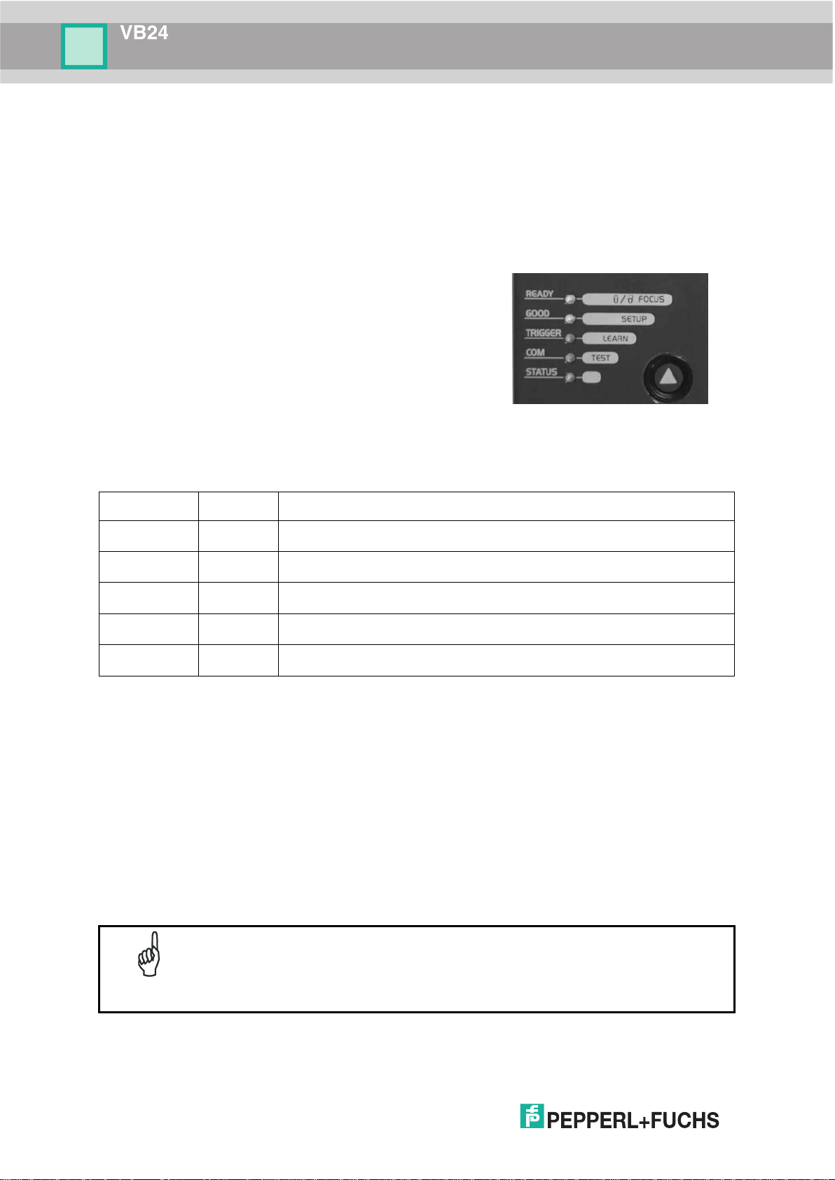
LED
Color
Description
READY
Green
This LED indicates the device is ready to operate.
GOOD
Green
This LED confirms successful reading.
TRIGGER
Yellow
This LED indicates the status of the reading phase. *
COM
Yellow
This LED indicates active communication on main serial port. **
STATUS
Red
This LED indicates a NO READ result.
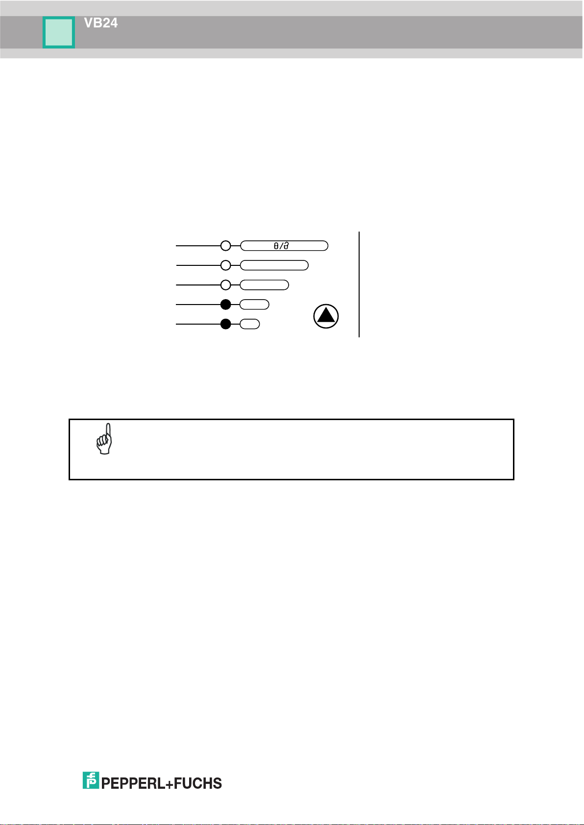
STEP 4 – MODE CONFIGURATION
Mode is the intuitive Human Machine Interface designed to improve ease of installation and
maintenance.
Status and diagnostic information are clearly presented by means of the five colored LEDs,
whereas the single push button gives immediate access to the following relevant functions:
• AutoSetup to self-optimize and auto-configure
reading performance in demanding applications
• AutoLearn to self-detect and auto-
reading unknown barcodes (by type and length)
• Focus Lock to memorize the mechanical focus
position
• Test Mode with bar graph visualization to check
The colors and meaning of the five LEDs are illustrated in the following table:
* In On-Line mode the TRIGGER LED corresponds to the active reading phase signaled by the Presence Sensor.
In Automatic and Continuous modes the TRIGGER LED is always on indicating that the reader is ready to read a
code.
** When connected to a Fieldbus network through the CBX500, the COM LED is always active, even in the
absence of data transmission, because of polling activity on the Fieldbus network.
During the reader startup (reset or restart phase), all the LEDs blink for one second.
On the back of the reader near the cable, the “POWER ON” LED indicates the laser scanner is
correctly powered.
When entering the Mode interface on the VB24-X1XX the Oscillating Mirror
NOTE
remains in the default fixed position (0°) in order to make barcode reading
easier while performing the Mode functions.
Page 17
VB24
7
green
green
yellow
yellow
red
READY
GOOD
TRIGGER
COM
STATUS
SETUP
LEARN
TEST FOCUS
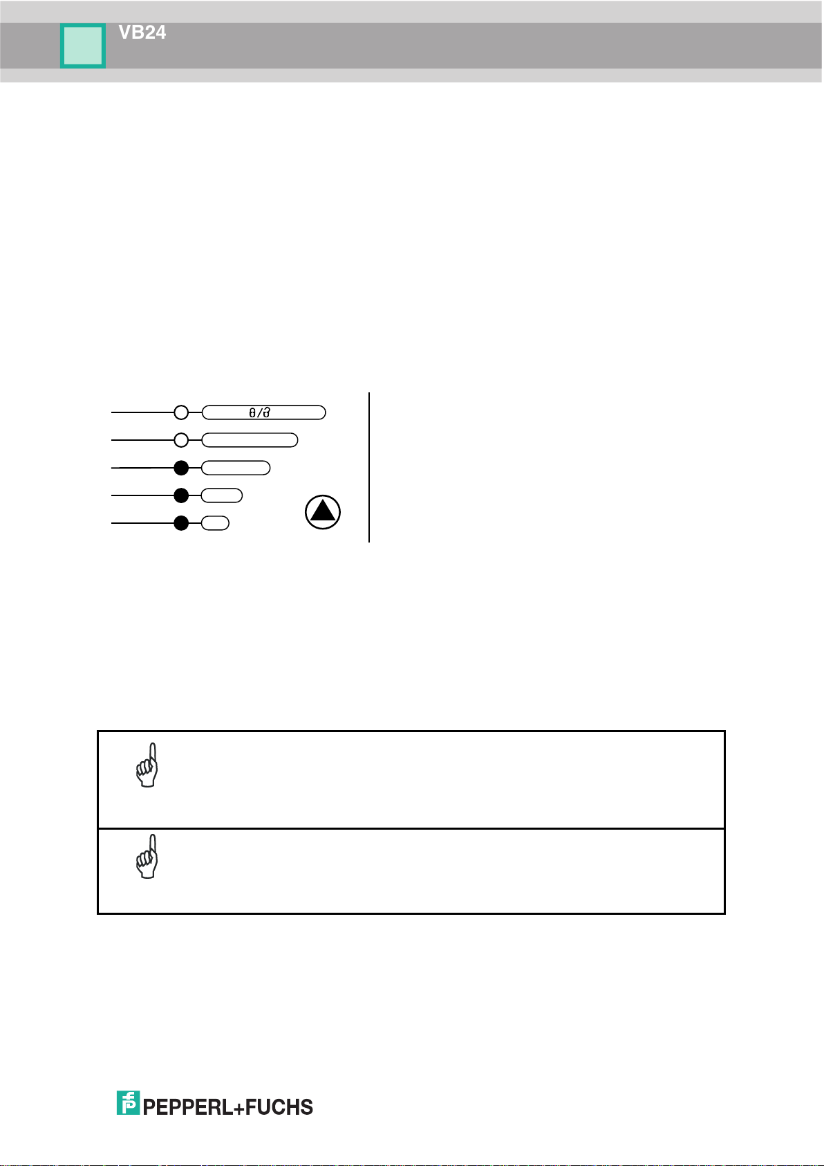
The procedure is as follows:
e LEARN LED
reader has detected the
, if needed, the above
LED returns to the blinking
mode is enabled.
If the barcode cannot be read because of low contrast or excessive ambient
light, you can perform the AutoSetup function to optimize the optical
owing parameters are forced: Code
Auto Learn
If you are configuring your scanner using Mode push button, you must start with the Auto
Learn procedure.
1. Enter the Auto Learn function by holding the Mode push button pressed until the LEARN
LED is on.
2. Release the button to enter the Auto Learn function.
Once entered, the reader starts a procedure to automatically detect and recognize
barcodes (by type and length), which are presented to it (*). The laser turns on and the
LEARN LED blinks to indicate the ongoing process.
A) place the desired barcode on
the scanline.
B) wait until th
stays steady on (indicating the
Figure 5 – Mode Interface: Auto Learn Function
3. Exit the process by pressing the Mode push button once. The scanner will restart at the
end of the process, and then the detected barcodes are automatically configured in
scanner memory.
NOTE
NOTE
barcode).
C) repeat
two steps to program up to 10
different barcodes (the LEARN
state for the next code). If more
than one barcode is detected
in the scan line, the Multi Label
parameters. Then you can perform AutoLearn to recognize the barcode
symbology.
On exit from Autolearn, the foll
Combination = Single Label, Reading Mode = Linear. If necessary, these
parameters can be changed through Genius™.
Page 18
VB24
8
green
green
yellow
yellow
red
READY
GOOD
TRIGGER
COM
STATUS
SETUP
LEARN
TEST FOCUS
The procedure is as follows:
the AutoSetup function
(the laser turns on and the
until the SETUP LED
reader has detected the
barcode)
Auto Setup (Optional)
At the end of the Auto Learn procedure, you have the possibility to follow the Auto Setup
procedure to set up the reading parameters.
1. Enter the Auto Setup function by holding the Mode push button pressed until the SETUP
LED is on.
2. Release the button to enter the Auto Setup function.
3. Once entered, if a barcode label is positioned in front of the scanline, the scanner
automatically performs the optimal setup of the reading parameters for that specific
barcode.
A) place the desired barcode on
the scanline.
B) enter
SETUP LED blinks to indicate
the ongoing process)
Figure 6 – Mode Interface: Auto Setup Function
C) wait
stays steady on (indicating the
This procedure ends either when the barcode is successfully decoded or after a timeout of
about 7 (seven) seconds.
The scanner will restart at the end of the process, and then the optimized reading parameters
for that barcode are automatically configured in scanner memory.
Page 19
VB24
9
green
green
yellow
yellow
red
READY
GOOD
TRIGGER
COM
STATUS
SETUP
LEARN
TEST
FOCUS
The procedure is as follows:
message appears on the display
(indicating the focus position has
been saved to memory). The
(default to display only)
Focus Lock/Unlock
You must perform the Focus Lock procedure to save the mechanical focus position to
memory. If the mechanical focus position is changed by more than the allowed tolerance of
the value in memory, a diagnostic alarm will be sent to the display.
1. Enter the Focus Lock function by holding the Mode push button pressed until the FOCUS
LOCK LED is on.
2. Release the button to enter the Focus Lock function.
Once entered, the scanner automatically performs the Lock (saving) or Unlock procedure
depending on the previous state of the Locked Position parameter.
A) enter the Focus Lock function
B) wait until the "Focus locked at..."
Figure 7 – Mode Interface: Focus Lock/Unlock Function
The scanner will restart at the end of the process.
If your application has been configured using Mode, go to STEP 6.
NOTE
Reset Scanner to Factory Default (Optional)
If it ever becomes necessary to reset the scanner to the factory default values, you can
perform this procedure by holding the Mode push button pressed while powering up the
scanner. At the end of the procedure (about 5-6 seconds), the Configuration and
Environmental parameters are reset, all LEDs blink simultaneously 3 times and the message
"Default Set" is shown on the display.
following parameters are set:
• Locked Position = your mechanical
setting
• Focus Displacement (Alarm) = set
Page 20

VB24
10
STEP 5 – INSTALL GENIUS™ CONFIGURATION PROGRAM
Genius
• Wizard approach for new users;
• Multi-language version;
• Defined configuration directly stored in the reader;
• Communication protocol independent from the physical interface allowing to consider the
This configuration procedure assumes scanner connection to a CBX100/500. Genius™,
running on a laptop computer, is connected to the scanner auxiliary port through the
CBX100/500 9-pin connector. To communicate with the scanner, Genius™ performs an auto
baudrate detection starting from its default parameters which are 115200, 8, N, 1. These
parameters can also be set in the Genius™ Tools>Options>Communications window.
Wizard for Quick Reader Setup
™
is a scanner configuration tool providing several important advantages:
reader as a remote object to be configured and monitored.
After installing the Genius™ software program the following window appears asking the user
to choose the desired configuration level.
Figure 8 - Genius™ Wizard Opening Window
The Wizard option is advised for rapid configuration or for new users, since it shows a step-bystep scanner configuration.
Page 21
VB24
11
1. Select the Create a new configuration button.
You will be guided through the configuration being asked to define the following
parameters:
a. Barcode selection and definition
Page 22
VB24
12
b. Operating mode selection and definition
c. Digital Outputs configuration
Page 23
VB24
13
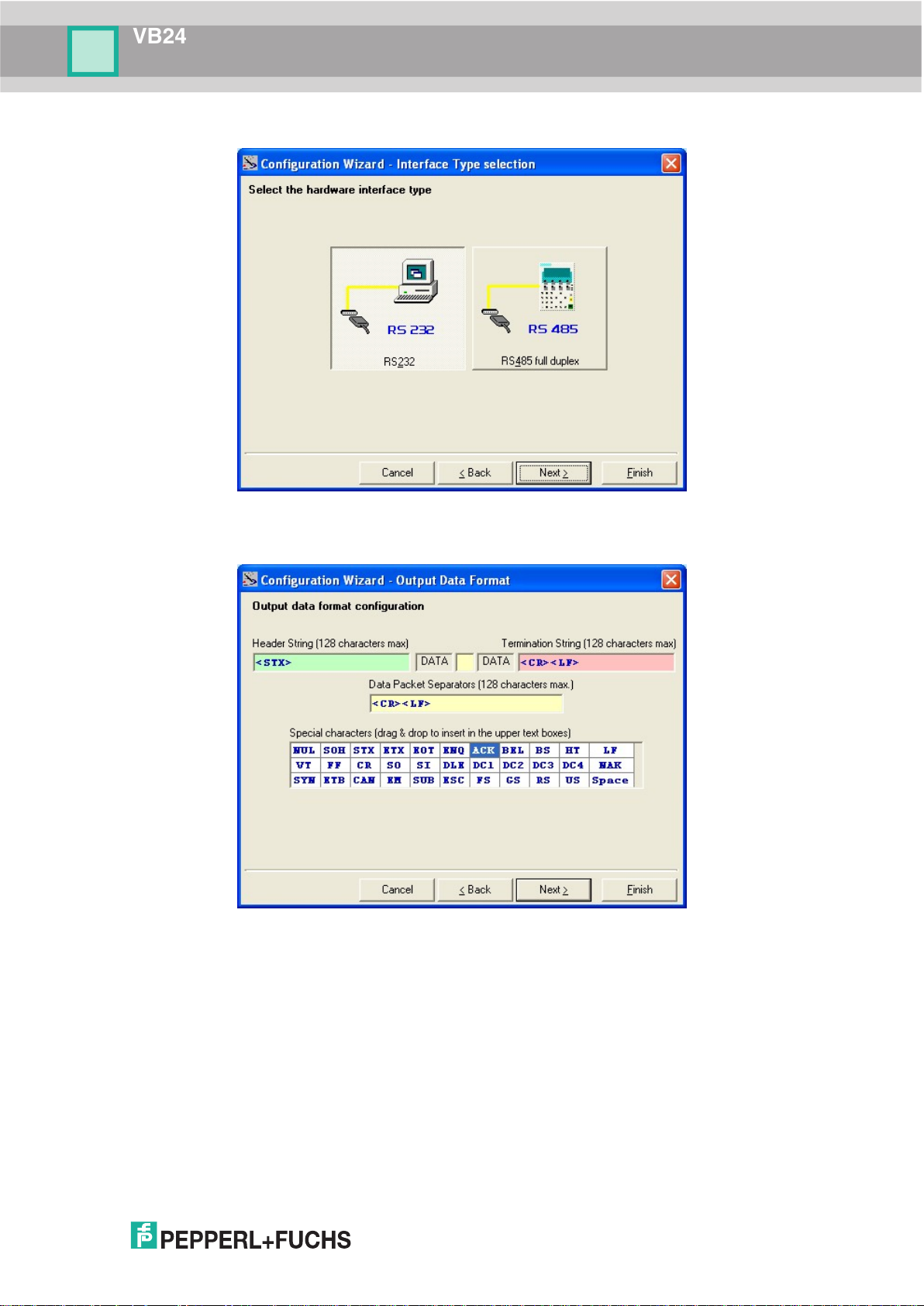
d. Hardware interface selection
e. Output data format configuration
The On Line operating Mode requires the reader to be connected to an External
Trigger/Presence Sensor using I1A and I1B inputs.
The Automatic operating mode does not require connection to an external Presence
Sensor. When working in this mode the reader is continuously scanning, while the
reading phase is activated each time a barcode enters the reader reading zone. The
reader stops reading after an N number of scans without a code. Barcode characters
are transmitted on the serial interface. In case of a failed reading phase no message is
sent to the host computer.
Page 24

VB24
14
3. After sending the configuration to the
scanner you have completed the
4. By clicking Finish, the System
Information window will be displayed
scanner.
2. After defining the parameter values the following window appears allowing to complete the
reader configuration as follows:
• Saving the configuration to disk;
• Switching to Advanced mode;
• Sending the configuration to the scanner.
configuration process.
with specific information concerning the
Page 25
VB24
15
green
green
yellow
yellow
red
READY
GOOD
TRIGGER
COM
STATUS
SETUP
LEARN
TEST
FOCUS
STEP 6 – TEST MODE
Use a code suitable to your application to test the system.
1. Enter the Test mode function by holding the Mode push button pressed until the TEST
LED is on.
2. Release the button to enter the Test mode function.
Once entered, the Bar-Graph on the five LEDs is activated and if the scanner starts
reading barcodes the Bar-Graph shows the Good Read Rate. In case of no read condition,
only the STATUS LED is on and blinks.
Figure 9 – Mode Interface: Test Mode Function
3. To exit the Test Mode, press the Mode push button once.
By default, the Test Mode exits automatically after two minutes.
NOTE
Page 26
VB24
16
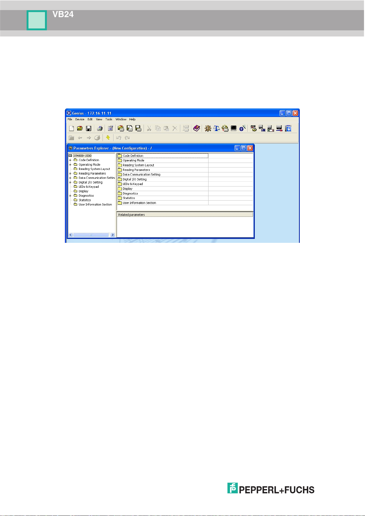
ADVANCED SCANNER CONFIGURATION
The ADVANCED selection available when starting the Genius™ program is addressed to
expert users being able to complete a detailed scanner configuration. By choosing this option
it is possible either to start a new scanner configuration or to open and modify an old one. The
desired parameters can be defined in the following window, similar to the MS Explorer:
Figure 10 - Genius™ Parameter Explorer Window
Host Mode Programming
The scanner can also be configured from a host computer using the Host Mode programming
procedure, by commands via the serial interface. See the Host Mode Programming file on the
webpage.
Alternative Layouts
• The ID-NET™ network is a built-in high-speed interface dedicated for high-speed scanner
interconnection. ID-NET™ is in addition to the Main and Auxiliary serial interfaces. If you
need to install an ID-NET™ network refer to the VB24 Reference Manual.
The scanner can also be configured by reading programming barcodes. See the "Setup
Procedure Using Programming Barcodes" printable from the webpage.
• If you need to install an Ethernet network, Fieldbus network, Pass-Through network,
Multiplexer network or an RS232 Master/Slave network refer to the VB24 Reference
Manual.
Page 27

VB24
17
Standard Application
A standard application program is factory-loaded onto the VB24.
ough the
, or via the serial interface (Genius™
based Host Mode Programming).
2 INTRODUCTION
2.1 PRODUCT DESCRIPTION
The VB24 laser scanner satisfies the most advanced needs of a wide range of users. It has
been developed focusing on the realistic requirements of its target market. The outstanding
result is an extremely compact, cost-effective and easy to use industrial scanner.
Program
This program controls barcode reading, serial port interfacing, data
formatting and many other operating and control parameters.
It is completely configurable from a host computer thr
Genius™ utility program
Some of the main features of VB24 are listed below:
• ACR4™ (Advanced Code Reconstruction – 4
• small dimensions and light weight
• software programmable scanning speed
• completely configurable via serial interface (Genius™)
• 3 serial communication interfaces (Main, Auxiliary, ID-NET™)
• supply voltage from 10 to 30 Vdc
• reads all popular codes
• test mode to verify the reading features and exact positioning of the scanner without the
th
Generation)
need for external tools
• programmable in 4 different operating modes to suit the most various barcode reading
system requirements
• code verifier
• low power consumption
The VB24 uses a solid-state laser diode as a light source; the light emitted has a wavelength
between 630 and 680 nm. Refer to the section “Safety Precautions” at the beginning of this
manual for information on laser safety.
The protection class of the enclosure is IP65, the reader is therefore suitable for industrial
environments where high protection against harsh external conditions is required.
Page 28
VB24
18
LED
Color
Description
READY
Green
This LED indicates the device is ready to operate.
GOOD
Green
This LED confirms successful reading.
TRIGGER
Yellow
This LED indicates the status of the reading phase. *
COM
Yellow
This LED indicates active communication on main serial port. **
STATUS
Red
This LED indicates a NO READ result.
ID-NET™ interface allows local connection
of multiple scanners reading different sides
of the same target. All scanners share a
single presence sensor and
each reading phase a single
NET™, data communication
among scanners is highly efficient so that
2.1.1 Indicators
The five LEDs on the side of the scanner (Figure A
* In On-Line mode the TRIGGER LED corresponds to the active reading phase signaled by the Presence Sensor.
In Automatic and Continuous modes the TRIGGER LED is always on indicating that the reader is ready to read a
code.
** When connected to a Fieldbus network through the CBX500, the COM LED is always active, even in the
absence of data transmission, because of polling activity on the Fieldbus network.
During the reader startup (reset or restart phase), all the LEDs blink for one second.
On the back of the reader near the cable, the “POWER ON” LED indicates the laser scanner is
correctly powered.
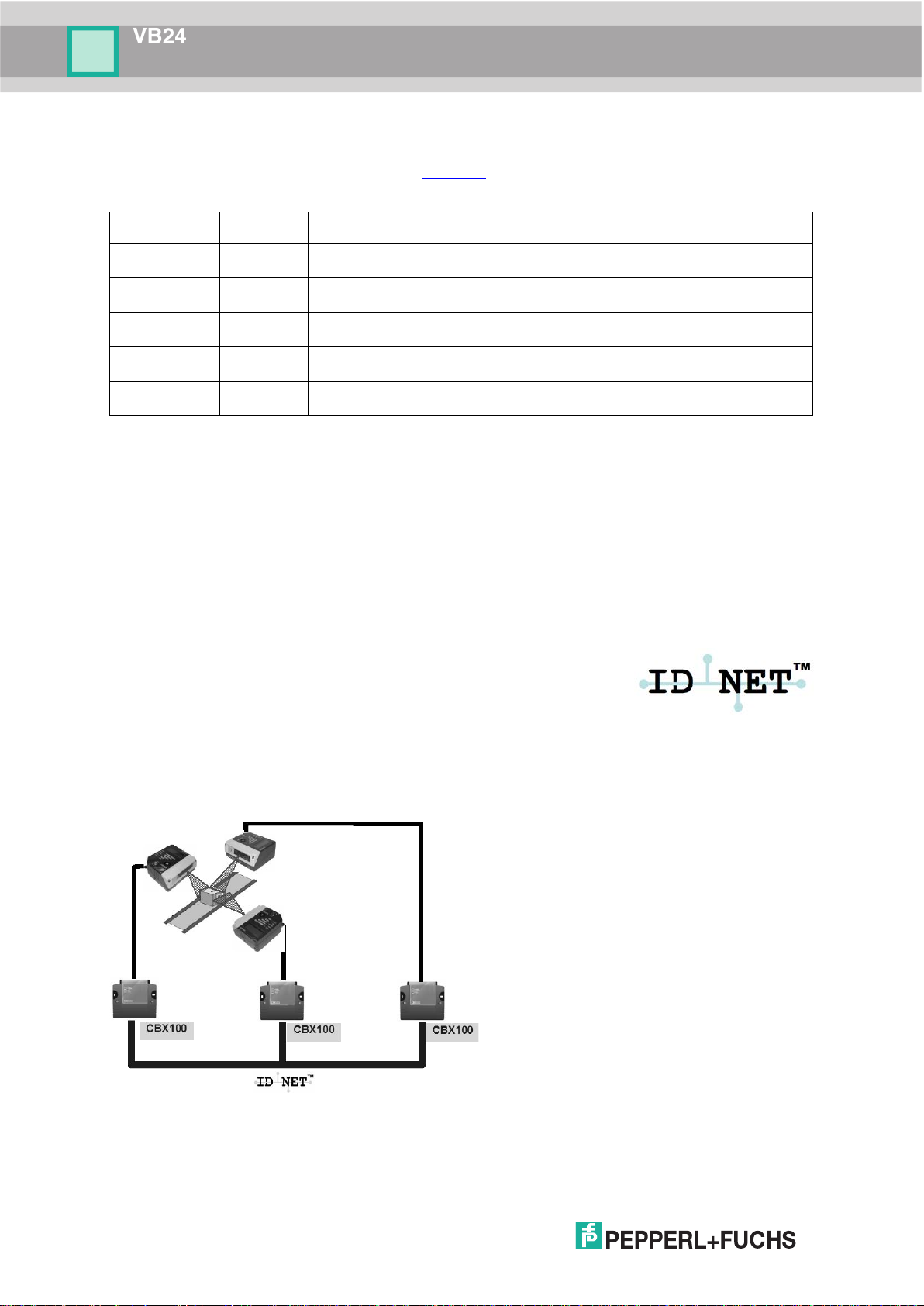
2.2 ID-NET™
The ID-NET™ network is a built-in high-speed interface dedicated
for high-speed scanner interconnection. ID-NET™ is in addition to
the Main and Auxiliary serial interfaces.
The following network configurations are available:
ID-NET™ M/S Synchronized: Single station – multiple scanners
, 3) indicate the following:
activate/deactivate simultaneously.
At the end of
data message is transmitted to the host.
Thanks to ID-
an immediate result will be available.
Page 29

VB24
19
ID-NET™ M/S Multidata: Multiple stations – single scanner
ID-NET™ interface allows connection of scanners reading objects placed on independent
conveyors. All scanners are typically located far away from each other and they use a
dedicated presence sensor.
At the end of each reading phase, each scanner transmits its own data message to the host.
Thanks to ID-NET™, data collection among readers is accomplished at a high speed without
the need of an external multiplexing device. This leads to an overall cost reduction and to a
simple system wiring.
Page 30
VB24
20
If necessary, the ID-NET™ baudrate can be set individually on each Slave
Baudrate parameter. Then follow the
2.2.1 How To Setup/Configure the Scanner Network
A complete ID-NET™ scanner network can be rapidly setup, as follows:
Mounting & Connection
1. Mechanically mount/install all the readers (refer to par. 3.2 and 3.3).
2. Wire ID-NET™ (refer to par. 4.3 or 5.3).
3. Connect a PC equipped with Genius™ to the planned Master scanner.
4. Power up the entire system.
Configuration
1. Launch Genius™.
2. From the Genius™ Device Menu select “Local Device Network Settings” and program the
Role of the Master scanner (Synchronized or Multidata).
This procedure requires the Network Baud Rate be the same for all Slaves and Master,
(500 kbs is the default value). It can be changed after network setup using Genius™
through the Master scanner. See also the alternative procedure in the note below.
3. At the prompt to "Send updated Network configuration to the Local Device" (Master)
choose "Yes".
4. Then run the NET-AUTOSET procedure from the Icon in the Devices Area. Genius™ sets
all slave scanners according to the Master Role (Synchronized or Multidata), and assigns
each a random address. If necessary, this address can be changed through the Network
Wizard.
5. Configure the System parameters via Genius™.
6. If using the CBX connection box equipped with a BM100 Backup module, perform System
Backup at the Master.
The scanner network is ready.
scanner to match the Master. Connect each Slave to Genius™ and set the
NOTE
Reading System Layout > Network
procedure above.
An alternative method of programming scanner address and role assignment
NOTE
can be accomplished by using the “Connectivity Programming Barcodes”
(refer to the “Setup Procedure Using Programming Barcodes” document).
Page 31

VB24
21
The intuitive Human Machine Interface designed with the
precise goal of improving ease of installation and
maintenance.
Status and diagnostic information are clearly presented
function key gives immediate access to relevant
to memorize the mechanical focus
static reading performance
READY
GOOD
TRIGGER
COM
STATUS
SETUP
LEARN
TEST
FOCUS
LED
STATUS
READY
BLINK
ON to indicate any Failure different than
TRIGGER
ON to indicate a Motor Failure.
COM
ON to indicate a Laser Failure.
STATUS
BLINK
2.3 HUMAN MACHINE INTERFACE
Fehler! Textmarke nicht definiert.
by means of five-colored LEDs, whereas the single multi-
functions:
• Autosetup to self-optimize reading performance
in demanding applications
• Autolearn to self-detect unknown barcodes
• Focus Lock
position
• Test Mode with bar-graph visualization to check
Mode push button is the common interface adopted in all new products: “You learn one, you
can use them all”.
The colors and meaning of the five LEDs when in the one of the operating modes (On-Line,
Automatic or Continuous) are illustrated in par 2.1.1.
Except for the Focus Lock/Unlock function, the Mode functions do not work if
the motor or laser are turned off, see chp. 9 for details.
NOTE
2.3.1 Diagnostic Indication
The “STATUS” and “READY” LEDs blink simultaneously to signal the presence of a failure.
Diagnostic message can be enabled to provide details about specific failure conditions. These
messages will be shown on the display and if enabled for transmission, also on the selected
interfaces.
At the same time one or more LEDs light up according to the following scheme:
VB24 also shows specific diagnostic messages on its display, see par. 2.4 for details.
GOOD
Motor or Laser failures.
Page 32

VB24
22
Quick access to the following functions is provided by
an easy procedure using the push button:
1
2
3 – Release the button to enter the specific function.
READY
GOOD
TRIGGER
COM
STATUS
SETUP
LEARN
TEST
FOCUS
READY
GOOD
TRIGGER
COM
STATUS
SETUP
LEARN
TEST
FOCUS
READY
GOOD
TRIGGER
COM
STATUS
SETUP
LEARN
TEST
FOCUS
READY
GOOD
TRIGGER
COM
STATUS
SETUP
LEARN
TEST
FOCUS
Release button to
Exit
Release button to
enter Test Mode
Release button to
enter AutoLearn
READY
GOOD
TRIGGER
COM
STATUS
SETUP
LEARN
TEST
FOCUS
READY
GOOD
TRIGGER
COM
STATUS
SETUP
LEARN
TEST
FOCUS
READY
GOOD
TRIGGER
COM
STATUS
SETUP
LEARN
TEST
FOCUS
Release button to
enter AutoSetup
(cycle)
Release button to
Exit
2.3.2 Mode Functions
– Press the button (the STATUS LED will give a
visual feedback).
– Hold the button until the specific function LED is
on (TEST, LEARN or SETUP).
Once button is pressed, the cycle of LEDs activation is as follows:
Release button to
enter Focus Lock/Unlock
Test Mode Function
Once entered, the Bar-Graph on the five LEDs is activated and if the scanner starts reading
barcodes the Bar-Graph shows the Good Read Rate. In case of no read condition, only the
STATUS LED is on and blinks.
To exit the Test Mode, press the Mode push button once.
Page 33

VB24
23
The AutoSetup function does not modify the programmed barcode
AutoLearn Function
Once entered, the reader starts a procedure to automatically detect and recognize barcodes
(by type and length), which are presented to it
to indicate the ongoing process.
The procedure is as follows:
- place the desired barcode on the scanline.
- wait until the LEARN LED stays steady on (indicating the reader has detected the
barcode).
- repeat, if needed, the above two steps to program up to 10 different barcodes (the LEARN
LED returns to the blinking state for the next code). If more than one barcode is detected in
the scan line, the Multi Label mode is enabled.
- exit the process by pressing the Mode push button once.
The scanner will restart at the end of the process, and then the detected barcodes are
automatically configured in scanner memory.
AutoSetup Function
Once entered, if a barcode label is positioned in front of the scanline, the scanner
automatically performs the optimal setup of the reading parameters for that specific barcode.
The procedure is as follows:
1
. The laser turns on and the LEARN LED blinks
- place the desired barcode on the scanline.
- enter the AutoSetup function (the laser turns on and the SETUP LED blinks to indicate the
ongoing process).
- wait until the SETUP LED stays steady on (indicating the reader has detected the
barcode).
This procedure ends either when the barcode is successfully decoded or after a timeout of
about 7 (seven) seconds.
The scanner will restart at the end of the process, and then the optimized reading parameters
for that barcode are automatically configured in scanner memory.
NOTE
symbologies. If needed, the AutoLearn function can be performed after
Autosetup.
Page 34

VB24
24
Priority
Message Type
0:
File Transfer, Backup & Restore, Restore Default Parameters
1:
Mode Menu Selection
2:
Focus Setup Procedure
3:
Diagnostic Alarms *
4:
Reading Results
5:
Welcome Message 2
Focus Lock/Unlock
Once entered, the scanner automatically performs the Focus Lock procedure to save the
mechanical focus position to memory. If the mechanical focus position is changed by more
than the allowed tolerance of the value in memory, a diagnostic alarm will be sent to the
display.
The procedure is as follows:
- enter the Focus Lock function.
- wait until the "Focus locked at..." message appears on the display (indicating the focus
position has been saved to memory). The following parameters are set:
• Locked Position = your mechanical setting
• Focus Displacement (Alarm) = set (default to display only)
If the Focus lock has already been set, this procedure can be used to Unlock the focus value.
In this case control of the focus position is disabled.
The scanner will restart at the end of the process.
Reset Scanner to Factory Default
If it ever becomes necessary to reset the scanner to the factory default values, you can
perform this procedure by holding the Mode push button pressed while powering up the
scanner. At the end of the procedure (about 5-6 seconds), the Configuration and
Environmental parameters are reset, all LEDs blink simultaneously 3 times and the message
"Default Set" is shown on the display.
2.4 DISPLAY
The VB24 is equipped with a 2 line by 16 character LCD display which shows various
diagnostic, menu and operating mode messages according to a defined priority (0 = top
priority):
* Diagnostic Alarm Messages can be enabled/disabled in Genius™.
2
For Master devices only, Network Diagnos tics can be enabled through the Network Status Monitor parameter in Genius™
instead of the Welcome Message.
Page 35

VB24
25
A A A % Z Z Z Z Z Z Z Z Z Z Z F = X X X c m - Y Y . Y i
n
X X X X X X X X X
Y Y D G T A u t o l e a r n O k # Z Z
A l e r t : M o t o r S p e e d = X X X X / Y Y Y
Y
A l e r t : F a i l u r e # X X X
The display language for messages can be selected in Genius™. The currently supported
languages are:
• English (default)
• French
• German
• Italian
• Japanese
2.4.1 Display Messages
The following examples of VB24 Local Display messages are given to help interpret the
information reported.
Test Mode Results:
A = reading percentage from 000 to 100%.
Z = code content.
F = focus distance in given in centimetres and inches.
Autolearn Results:
X = recognized code symbology.
Y = number of digits in the read code
Z = number of configured slot (at the end of the procedure this number represents the total
slots configured).
Diagnostic Alarms:
X = expected speed
Y = actual speed
Generic Alarms:
X = numeric error value (even if User Defined Messages are selected for data transmission
the numeric error value is sent to the display)
Page 36

VB24
26
A l e r t : I D - N E T N o d e # X X F a i l # Y Y
Y
A A A A X X X X X X X X X X X Y Y C o d e s
G o o d X X X X X X X X X X X Y Y D G T D W W W S S
S
Slave Node Alarms:
X = slave node number (1-31)
Y = numeric error value
Reading Results:
A = reading result – Good (Good Read), Part (Partial Read), Mult (Multiple Read)
X = code content
Y = number of codes read
X = code content
Y = number of digits in the code
DGT = "digits"
D = code direction – F=forward, R=reverse, U=unknown
Linear Reading (only if the Quality Counters parameter is enabled)
W = number of scans on the code
S = Quality Counters value (max 100)
Code Reconstruction
W = number of scans on the code (max 255)
S = number of decodes (max 255), on the digit in the code which was decoded the least
number of times
Page 37

VB24
27
X X X X X X X X X X X X R R R K K K Y Y Y Y Y Y Y Y Y N N
N
S N X X X X X X X X X F = Z Z Z C M - Y Y . Y I
N
1 N e t w o r k 1 5 S S S S S S S S S S S S S S S
S
1 6 N e t w o r k 3 1 S S S S S S S S S S S S S S S
S
Message 1
Message 2
Message 1
Message 2
Welcome Message:
The display alternates between message 1 and 2.
X = scanner model
K = software – STD=Standard, SS=Special
Y = software version
R = Device Network Type – MUL=Multidata, SYN=Synchronized, ALN=Alone, MUX=Slave
Mux32, MST=Master RS232, SLV=Slave RS232
N = Device Network Setting – M00=ID-NET™ Network Master, Sxx= ID-NET™ Network
Slave address, Axx= Mux32 Slave address, 232= RS232 network, Null string= Alone (no
network)
X = device serial number
Z = focus position in cm
Y = focus position in inches
Network Diagnostic Messages (Master only):
The display alternates between message 1 and 2.
S = Slave diagnostic condition:
* = scanner OK
- =scanner not detected at startup
? =scanner detected at startup but not responding to diagnostic polling
! = scanner diagnostic error
Page 38

VB24
28
3 INSTALLATION
3.1 PACKAGE CONTENTS
Verify that the VB24 reader and all the parts supplied with the equipment are present and
intact when opening the packaging; the list of parts includes:
• VB24 reader with cable
• Mounting Kit: - bracket
- screws
- flat washers
- lock washers
Figure 11- VB24 Package Contents
Page 39

VB24
29
85
M4
M4
M4
M4
81
[3.19]
87.7
[3.45]
37
[1.46]
41.9
[1.65]
37.8
[1.49]
27.9
[1.10]
12.1
[0.48]
5.2
[0.21]
M5
M5
7.5
[0.30]
34
[1.34]
10
[0.39]
13
[0.51]
10
[0.39]
41.4
[1.63]
M5
42
[1.65]
mm
3.2 MECHANICAL INSTALLATION
VB24 can be installed to operate in different positions. The four screw holes (M4 x 5) on the
body of the reader are for mechanical fixture to the L-shaped mounting bracket.
There are also three screw holes (M5 x 3) for fixture to the U-shaped mounting bracket.
The following diagrams give the overall dimensions of the scanner and mounting brackets and
may be used for installation. Refer to par. 0 and 3.3 for correct positioning.
[in]
[3.34]
101
[3.98]
Figure 12 – VB24 Overall Dimensions
Page 40

VB24
30
55
[2.17]
10
[0.39]
=
70
[2.76]
=
80
[3.15]
Ø4.2
Ø4.2
[Ø0.17] N°4
30°
Ø8.1
[Ø0.32] N°2
8.1
[0.32] N°6
70
[2.76]
120
[4.72]
3
[0.12]
4.2
[0.17]
71.6
[2.82]
100.6
[3.96]
103
[4.06]
74
[2.91]
=
76.9
[3.03]
=
3
[0.12]
108
[4.25]
30
[1.18]
64.2
[2.53]
70
[2.76]
==
Ø5.5
[Ø0.22] N°2
56
[2.20]
15°
15°
45°
45°
9
[0.35]
==
27.5
[1.08]
45°
45°
45°
45°
15°
15°
15°
15°
64.2
[2.53]
Ø5.5
[Ø0.22]
8.1
[0.32] N°2
mm
mm
[in]
Figure 13 – L Shape Mounting Bracket Overall Dimensions
[in]
Figure 14 – U Shape Mounting Bracket Overall Dimensions
Page 41

VB24
31
Skew
-45° -15° 0° 15° 45°
Pitch
Mounting VB24
Using the VB24 mounting bracket you can quickly and easily obtain standard mounting
positions (i.e. 15° Skew angles) for the reader as shown in the following figures:
Figure 15 – Positioning with L Shape Mounting Bracket
Page 42

VB24
32
Pitch
Skew
0°
15°
45°
-45°
-15°
alignment marks
Figure 16 – Positioning with U Shape Mounting Bracket
Page 43

VB24
33
T S T
S
3.3 POSITIONING
The VB24 scanner is able to decode moving barcode labels at a variety of angles, however
significant angular distortion may degrade reading performance.
When mounting the VB24 take into consideration these three ideal label position angles: Skew
15° to 30°, Tilt 0° and Pitch 0°.
Follow the suggestions for the best orientation:
The Skew angle is represented by the value S in Figure 17. Position the reader to assure at
least 15° for the Skew angle. This avoids the direct reflection of the laser light emitted by the
VB24.
Figure 17 – VB24 Skew Angle
The Tilt angle is represented by the value T in Figure 18. Position the reader in order to
minimize the Tilt angle.
Figure 18 – VB24 Tilt Angle
By using the ACR4™ (Advanced Code Reconstruction) software parameter, the tilt angle is
less critical and can be decoded even if the scan line doesn’t cross the entire code.
See par. 7.1 or the Help On Line for details.
Page 44

VB24
34
P
P
The Pitch angle is represented by the value P in Figure 19. Position the reader in order to
minimize the Pitch angle.
Figure 19 – VB24 Pitch Angle
Page 45

VB24
35
CBX100/500 Terminal Block Connectors
Input Power
Vdc
Power Supply Input Voltage +
GND
Power Supply Input Voltage -
Earth
Protection Earth Ground
Inputs
+V
Power Source – External Trigger
I1A
External Trigger A (polarity insensitive)
I1B
External Trigger B (polarity insensitive)
-V
Power Reference – External Trigger
+V
Power Source – Inputs
I2A
Input 2 A (polarity insensitive)
I2B
Input 2 B (polarity insensitive)
-V
Power Reference – Inputs
Outputs
+V
Power Source - Outputs
-V
Power Reference - Outputs
O1+
Output 1 +
O1-
Output 1 -
O2+
Output 2 +
O2-
Output 2 -
Auxiliary Interface
TX
Auxiliary Interface TX
RX
Auxiliary Interface RX
SGND
Auxiliary Interface Reference
ID-NET™
REF
Network Reference
ID+
ID-NET™ network +
4 CBX ELECTRICAL CONNECTIONS
All VB24 models are equipped with a cable terminated by a 25-pin male D-sub connector for
connection to the power supply and input/output signals.
We recommend making system connections through one of the CBX connection boxes since
they offer the advantages of easy connection, easy device replacement and filtered reference
signals.
If you require direct wiring to the scanner the details of the connector pins
NOTE
The table below gives the pinout of the CBX100/500 terminal block connectors. Use this
pinout when the VB24 reader is connected by means of the CBX100/500:
and relative connections are indicated in Chaper 5.
Page 46

VB24
36
ID-
ID-NET™ network -
Shield
Network Cable Shield
Main Interface
RS485
Full-Duplex
RS485
Half-Duplex
TX
TX+
RTX+ RX
*RX+
RTS
TX-
RTX-
CTS
*RX-
SGND
SGND
SGND
V+
in
Earth
Ground
Power Supply
VGND
RS232
* Do not leave floating, see par. 4.2.2 for connection details.
To avoid electromagnetic interference when the scanner is connected to a
NOTE
CBX connection box, verify the jumper positions in the CBX as indicated in
its Installation Manual.
4.1 POWER SUPPLY
Power can be supplied to the scanner through the CBX100/500 spring clamp terminal pins as
shown in Figure 20:
The power must be between 10 and 30 Vdc only.
It is recommended to connect the device CHASSIS to earth ground (Earth) by setting the
appropriate jumper in the CBX connection box. See the CBX Installation Manual for details.
Figure 20 - Power Supply Connections
Page 47

VB24
37
4.2 MAIN SERIAL INTERFACE
Do not connect to the Main Interface spring clamp terminals if using Host
CAUTION
The signals relative to the following serial interface types are available on the CBX spring
clamp terminal blocks.
If the interface type is not compatible with the current communication handshaking, then the
system forces the handshake to none.
The main interface type and the relative parameters (baud rate, data bits, etc.) can be
set using the Genius™ utility program or the Genius™ based Host Mode
Programming procedure.
Details regarding the connections and use of the interfaces are given in the next paragraphs.
Interface Modules (Fieldbus) with the CBX500.
Page 48

VB24
38
CBX100/500
Function
TX
Transmit Data
RX
Receive Data
RTS
Request To Send
CTS
Clear To Send
SGND
Signal Ground
SGND RXD TXD
CTS RTS
USER INTERFACE
SGND TX RX
RTS CTS
SCANNER
4.2.1 RS232 Interface
The serial interface is used in this case for point-to-point connections; it handles
communication with the host computer and allows both transmission of code data and the
programming of the scanner. This is the default setting.
The following pins are used for RS232 interface connection:
It is always advisable to use shielded cables. The overall maximum cable length must be less
than 15 m (49.2 ft).
Figure 21 – RS232 Main Interface Connections Using Hardware Handshaking
The RTS and CTS signals control data transmission and synchronize the connected devices.
START
OF
+ V
RTS
- V
+ V
TX DATA
- V
+ V
CTS
- V
If the RTS/CTS handshaking protocol is enabled, the VB24 activates the RTS output to
TRANSMISSION
ENABLED
IDLE
Figure 22 - RS232 Control Signals
DATA
TRANSMISSION
C2
C1
TRANSMISSION
STOPPED
DISABLED
DATA
TRANSMISSION
C4
C3
ENABLED
END
OF
TRANSMISSION
C5
IDLE
indicate a message is to be transmitted. The receiving unit activates the CTS input to enable
the transmission.
Page 49

VB24
39
CBX100/500
Function
TX+
RS485 Transmit Data +
RX+
RS485 Receive Data +
TX-
RS485 Transmit Data -
RX-
RS485 Receive Data -
SGND
Signal Ground
RX485+ TX485+
SGND RX485- TX485-
USER INTERFACE
SGND TX+ RX+
TX- RX-
SCANNER
RX485+
SGND RX485-
USER INTERFACE
SGND TX+
TX-
SCANNER
4.2.2 RS485 Full-Duplex Interface
The RS485 full-duplex (5 wires + shield) interface is used for non-polled communication
protocols in point-to-point connections over longer distances (max 1200 m / 3940 ft) than
those acceptable for RS232 communications or in electrically noisy environments.
The CBX pinout follows:
Figure 23 - RS485 Full-duplex Connections
For applications that do not use RX485 signals, do not leave these lines
floating but connect them to SGND as shown below.
NOTE
Figure 24 - RS485 Full-duplex Connections using Only TX Signals
Page 50

VB24
40
CBX100/500
Function
RTX+
RS485 Receive/Transmit Data +
RTX-
RS485 Receive/Transmit Data -
SGND
Signal Ground
RTX485+
SGND RTX485-
USER INTERFACE
SGND RTX+
RTX-
SCANNER
4.2.3 RS485 Half-Duplex Interface
This interface is provided for backward compatibility. We recommend using
NOTE
The RS485 half-duplex (3 wires + shield) interface is used for polled communication protocols.
It can be used for Multidrop connections with a Pepperl+Fuchs GmbH Multiplexer, (see par.
6.5) exploiting a proprietary protocol based on polled mode called MUX32 protocol, where a
master device polls slave devices to collect data.
the more efficient ID-NET™ network for Master/Slave or Multiplexer layouts.
Figure 25 - RS485 Half-duplex Connections
This interface is forced by software when the protocol selected is MUX32 protocol.
In a Multiplexer layout, the Multidrop address must also be set via serial channel by the
Genius™ utility or by the Host Programming Mode.
Figure 26 shows a multidrop configuration with VB24 scanners connected to a Multiplexer.
CAUTION
This is an example of multidrop wiring. Consult the multiplexer manual for
complete wiring instructions.
Page 51

VB24
41
Multidrop Cable
Vdc
*
*
Power Supply
Scanner
Slave
#0
MULTIPLEXER
120 Ohm
Shield to Earth
CBX100/500
RS485 HD
Termination Resistor.
Power Supply
VV+
Main Interface
Multidrop Multidrop +
Multidrop GND
Shield
SGND
Shield
floating
Shield
OFF
HOST
RS232/RS485
RTXRTX+
1200 m Max Length
Earth
GND
Vdc
CBX100/500
Scanner
Slave
#1
RS485 HD
Termination Resistor.
Power Supply
Shield
floating
OFF
RTX-
RTX+
SGND
Shield
Earth
GND
Vdc
CBX100/500
Scanner
Slave
(up to 31)
RS485 HD
Termination Resistor.
Power Supply
ON
Shield
floating
RTX-
RTX+
SGND
Shield
Earth
GND
Figure 26 – VB24 Multidrop Connection to a Multiplexer
* When using CBX500, the Main interface multidrop network signals: Shield, SGND, RTX+and RTX- are repeated
on terminal connector row 4 to facilitate system cabling.
Page 52

VB24
42
CBX100/500
Function
Shield
Network Cable Shield
ID+
ID-NET™ network +
ID-
ID-NET™ network -
REF
Network Reference
Baudrate Table
Baud Rate
125 kbps
250 kbps
500 kbps
1Mbps
Cable Length
1200 m
900 m
700 m
*
NET™ baudrates
s. The baudrate is software configurable by
4.3 ID-NET™ INTERFACE
4.3.1 ID-NET™ Cables
The following instructions are referred to Figure 28, Figure 29 and Figure 30.
• The general cable type specifications are: CAT5 twisted pair + additional CAT5 twisted
pair, shielded cable AWG 24 (or AWG 22) stranded flexible.
We recommend using DeviceNet cables (drop or trunk type) to the following reference
standards:
AN50325 – IEC 62026
UL STYLE 2502 80°C 30V
• Cable Shield MUST be connected to earth ground ONLY at the Master.
• NEVER use ID-NET™ cable shield as common reference.
• The ID-NET™ max cable length depends on the baudrate used, (see the Baudrate Table
below).
• For Common Power Connections use only 2 wires (ID+ and ID-).
- DC Voltage Power cable (Vdc – GND) should be handled as a signal cable (i.e. do not
put it together with AC cable):
- Wire dimensioning must be checked in order to avoid voltage drops greater than 0.8
Volts.
- Cable should lie down as near as possible to the ID-NET™ cable (avoiding wide loops
between them).
• Scanner's chassis may be connected to earth.
• Network inside the same building.
* Application dependent, contact your Pepperl+Fuchs GmbH representative for details.
NOTE
The default ID-NET™ baudrate is 500 kbps. Lower IDallow longer cable length
authorized Pepperl+Fuchs GmbH personnel only.
Page 53

VB24
43
240
220
200
180
160
140
120
100
80
60
40
20
0
Response Time (ms)
Number of Nodes
500 kbps
250 kbps
125 kbps
0 1 2 3 4 5 6 7 8 9 10
11
12
13
14
15
16
4.3.2 ID-NET™ Response Time
The following figure shows the response time of the ID-NET™ network. This time is defined as
the period between the Trigger activation and the beginning of data transmission to the Host.
Max ID-NET™ Response Time
Figure 27 – ID-NET™ Response Time
CONDITIONS:
• ID-NET™ M/S Synchronized layout
• message length = 50 bytes per node
Page 54

VB24
44
Power Supply
Power Supply
Power Supply
Figure 28 – ID-NET™ Network Connections with isolated power blocks
Page 55

VB24
45
Figure 29 - ID-NET™ Network Connections with Common Power Branch Network
Page 56

VB24
46
Figure 30 – ID-NET™ Network Connections with Common Power Star Network
Page 57

VB24
47
5
1
6
9
CBX100/500
Function
RX
Auxiliary Interface Receive Data
TX
Auxiliary Interface Transmit Data
SGND
Auxiliary Interface Reference
RX TX
Reference
USER INTERFACE
4.3.3 ID-NET™ Network Termination
The network must be properly terminated in the first and last scanner of the network. This is
done by setting the ID-NET™ Termination Resistance Switch in the CBX100/500 to ON.
4.4 AUXILIARY RS232 INTERFACE
The auxiliary serial interface is used exclusively for RS232 point-to-point connections.
The parameters relative to the aux interface (baud rate, data bits, etc.) as well as particular
communication modes such as LOCAL ECHO can be defined using the Genius™ utility
program or Genius™ based Host Mode Programming.
The 9-pin female Auxiliary Interface connector inside the CBX is the preferred connector for
device configuration or communication monitoring.
Figure 31 - 9-pin female connector
If permanent system wiring is required, the following pins are used to connect the RS232
auxiliary interface:
Do not connect the Aux Interface to the CBX spring clamp connectors and
NOTE
the 9-pin connector simultaneously.
Figure 32 - RS232 Auxiliary Interface Connections
Page 58

VB24
48
CBX100/500
Function
+V
Power Source - External Trigger
I1A
External Trigger A (polarity insensitive)
I1B
External Trigger B (polarity insensitive)
-V
Power Reference - External Trigger
(brown)
(black) (blue)
PH-1 Photocell (PNP)
4.5 INPUTS
There are two optocoupled polarity insensitive inputs available on the scanner: Input 1
(External Trigger) and Input 2, a generic input:
The electrical features of both inputs are:
Maximum voltage: 30 Vdc
Maximum current: 12 mA (scanner) + 12 mA (CBX)
An anti-disturbance filter is implemented in software on both inputs so that the minimum pulse
duration is ≅ 5 milliseconds. This value can be increased through the software parameter
Debounce Filter.
The External Trigger input is used in the On-Line operating Mode and tells the scanner to scan
for a code. The active state of this input is selected in software. Refer to the Genius™ Help On
Line.
The yellow Trigger LED (Figure A
, 3) is on when the active state of the External Trigger
corresponds to ON.
This input is optocoupled and can be driven by both an NPN and PNP type command. The
connections are indicated in the following diagrams:
EXTERNAL TRIGGER INPUT CONNECTIONS USING VB24 POWER
Figure 33 – PH-1 Photocell (PNP) External Trigger Using VB24 Power
Page 59

VB24
49
Power to Input
Photocell Signal
Photocell
Reference
NPN Photocell
Pulled down to External
Input Device Reference
Input
Signal
PNP Photocell
Pulled up to External
Input Device Power
Input
Signal
NPN Photocell
Figure 34 - NPN External Trigger Using VB24 Power
EXTERNAL TRIGGER INPUT CONNECTIONS USING EXTERNAL POWER
Figure 35 - PNP External Trigger Using External Power
Figure 36 - NPN External Trigger Using External Power
Page 60

VB24
50
CBX100/500
Function
+V
Power Source - Inputs
I2A
Input 2 A (polarity insensitive)
I2B
Input 2 B (polarity insensitive)
-V
Power Reference - Inputs
Power to
Input Device
Input Input Device
Signal Reference
Input Device
Power to Input
Input Device
Input Device
Reference
Input Device
Pulled down to External
Input Device Reference
Input
Signal
Input Device
Pulled up to External
Input Device Power
Input
Signal
Input Device
INPUT 2 CONNECTIONS USING VB24 POWER
PNP Input 2 Using VB24 Power
Signal
NPN Input 2 Using VB24 Power
INPUT 2 CONNECTIONS USING EXTERNAL POWER
Figure 37 - PNP Input 2 Using External Power
Figure 38 - NPN Input 2 Using External Power
Page 61

VB24
51
CBX100/500
Function
+V
Power Source - Outputs
O1+
Output 1 +
O1-
Output 1 -
O2+
Output 2 +
O2-
Output 2 -
-V
Power Reference Outputs
4.5.1 Code Verifier
If the VB24 is used as a Code Verifier, the verifier code can be configured in software through
the Genius™ configuration program. However it is also possible to use one of the inputs to
trigger when the scanner should store a code read as the verifier code.
The Code Verifier parameter must be enabled, and the configuration parameters to allow
correct Code Type reading must be saved to the scanner in order to read the verifier code.
When the selected input is activated, the next read code will be stored as the verifier code in
the scanner's non-volatile (Flash) memory.
4.6 OUTPUTS
Two general purpose outputs are available.
The meaning of the two outputs Output 1 and Output 2 can be defined by the user (No Read,
Right, Wrong, etc.). Refer to the Genius™ Help On Line.
By default, Output 1 is associated with the No Read event, which activates when the code
signaled by the external trigger is not decoded, and Output 2 is associated with the Complete
Read event, which activates when all the selected codes are correctly decoded.
The output signals are fully programmable being determined by the configured
Activation/Deactivation events, Deactivation Timeout or a combination of the two.
Page 62

VB24
52
Power to Output
Output device Signal
Output device
Reference
Output Device
Power to
Output device
Output device
Reference
Output Device
Output
Signal
Pulled up to External
Output Device Power
Output
Signal
Output Device
Pulled down to External
Output Device Reference
Output
Signal
Output Device
OUTPUT CONNECTIONS USING VB24 POWER
Figure 39 - Open Emitter Output Using VB24 Power
Figure 40 - Open Collector Output Using VB24 Power
OUTPUT CONNECTIONS USING EXTERNAL POWER
Figure 41 - Open Emitter Output Using External Power
Figure 42 - Open Collector Output Using External Power
VB
max = 30 Vdc
CEB
I max = 40 mA continuous; 130 mA pulsed
Page 63

VB24
53
RS232 PC-side connections
1
5
9
6
13
25
14
1
25-pin male connector
Pin
Name
Pin
Name
2
RX 3 RX
3
TX 2 TX
5
GND
7
GND
7
RTS
4
RTS
8
CTS
5
CTS
4.7 USER INTERFACE - HOST
The following table contains the pinout for standard RS232 PC Host interface. For other user
interface types please refer to their own manual.
9-pin male connector
Page 64

VB24
54
13
25
14
1
25-pin D-sub male connector pinout
Pin
Name
Function
13, 9
Vdc
Power supply input voltage +
25, 7
GND
Power supply input voltage -
1
CHASSIS
Cable shield connected to chassis
18
I1A
External Trigger A (polarity insensitive)
19
I1B
External Trigger B (polarity insensitive)
6
I2A
Input 2 A (polarity insensitive)
10
I2B
Input 2 B (polarity insensitive)
8
O1+
Output 1 +
22
O1-
Output 1 -
11
O2+
Output 2 +
12
O2-
Output 2 -
20
RX
Auxiliary Interface RX
21
TX
Auxiliary Interface TX
23
ID+
ID-NET™ network +
24
ID-
ID-NET™ network -
14, 15, 16, 17
NC
Not Connected
RS485
Full-Duplex
RS485
Half-Duplex
2
TX
TX+
RTX+
3
RX
*RX+
4
RTS
TX-
RTX-
5
CTS
*RX-
5 25-PIN CABLE ELECTRICAL CONNECTIONS
All VB24 models are equipped with a cable terminated by a 25-pin male D-sub connector for
connection to the power supply and input/output signals. The details of the connector pins are
indicated in the following table.
Figure 43 - 25-pin Male D-sub Connector
Pin Name RS232
MAIN INTERFACE
(SW SELECTABLE)
* Do not leave floating, see par. 5.2.2 for connection details.
Page 65

VB24
55
Earth Ground
POWER SUPPLY
CHASSIS
VGND
V+ (10 - 30 Vdc)
13
25
1
Vdc
GND
CHASSIS
VB24
5.1 POWER SUPPLY
Power can be supplied to the scanner through the pins provided on the 25-pin connector used
for communication with the host (Figure 44):
Figure 44 - Power Supply Connections
The power must be between 10 and 30 Vdc only.
It is recommended to connect pin 1 (CHASSIS) to a common earth ground.
5.2 MAIN SERIAL INTERFACE
The signals relative to the following serial interface types are available on the input/output
connector of VB24.
If the interface type is not compatible with the current communication handshaking, then the
system forces the handshake to none.
The main interface type and the relative parameters (baud rate, data bits, etc.) can be
set using the Genius™ utility program or the Genius™ based Host Mode
Programming procedure.
Details regarding the connections and use of the interfaces are given in the next paragraphs.
Page 66

VB24
56
25-pin
Name
Function
2
TX
Transmit Data
3
RX
Receive Data
4
RTS
Request To Send
5
CTS
Clear To Send
7
GND
Ground
VB24
7
4
5
3
GND
RTS
CTS
RX
TX
2
USER INTERFACE
GND
CTS
RTS
TXD
RXD
1
Chassis
5.2.1 RS232 Interface
The serial interface is used in this case for point-to-point connections; it handles
communication with the host computer and allows both transmission of code data and the
programming of the scanner. This is the default setting.
The following pins are used for RS232 interface connection:
It is always advisable to use shielded cables. The overall maximum cable length must be less
than 15 m (49.2 ft).
Figure 45 – RS232 Main Interface Connections Using Hardware Handshaking
The RTS and CTS signals control data transmission and synchronize the connected devices.
START
OF
+ V
RTS
- V
+ V
TX DATA
- V
+ V
CTS
- V
TRANSMISSION
ENABLED
IDLE
DATA
TRANSMISSION
C2
C1
TRANSMISSION
STOPPED
DISABLED
DATA
TRANSMISSION
C4
C3
ENABLED
Figure 46 - RS232 Control Signals
END
OF
TRANSMISSION
C5
IDLE
Page 67

VB24
57
25-pin
Name
Function
2
TX+
RS485 Transmit Data +
3
RX+
RS485 Receive Data +
4
TX-
RS485 Transmit Data -
5
RX-
RS485 Receive Data -
7
GND
Ground
VB24
TX+
2
TX-
4
RX+
3
RX485
RX-
5
TX485
7
GND
GND
USER INTERFACE
+
-
+
-
Chassis
1
VB24
TX+
2
TX-
4
RX+
3
RX485
RX-
5
7
GND
GND
USER INTERFACE
+
-
Chassis
1
If the RTS/CTS handshaking protocol is enabled, the VB24 activates the RTS output to
indicate a message is to be transmitted. The receiving unit activates the CTS input to enable
the transmission.
5.2.2 RS485 Full-Duplex Interface
The RS485 full-duplex (5 wires + shield) interface is used for non-polled communication
protocols in point-to-point connections over longer distances (max 1200 m / 3940 ft) than
those acceptable for RS232 communications or in electrically noisy environments.
The connector pinout follows:
NOTE
Figure 47 - RS485 Full-duplex Connections
For applications that do not use RX signals, do not leave these lines floating
but connect them to GND as shown below.
Figure 48 - RS485 Full-duplex Connections using Only TX Signals
Page 68

VB24
58
25-pin
Name
Function
2
RTX+
RS485 Receive/Transmit Data +
4
RTX-
RS485 Receive/Transmit Data -
7
GND
Ground
RTX+
2
RTX-
4
RTX485 +
RTX485 -
7
GND
MULTIPLEXER
RS485REF
VB24
1
Chassis
5.2.3 RS485 Half-Duplex Interface
This interface is provided for backward compatibility. We recommend using
NOTE
The RS485 half-duplex (3 wires + shield) interface is used for polled communication protocols.
It can be used for Multidrop connections with a Pepperl+Fuchs GmbH Multiplexer, (see par.
6.5) exploiting a proprietary protocol based on polled mode called MUX32 protocol, where a
master device polls slave devices to collect data.
The connector pinout follows:
the more efficient ID-NET™ network for Master/Slave or Multiplexer layouts.
Figure 49 - RS485 Half-duplex Connections
This interface is forced by software when the protocol selected is MUX32 protocol.
In a Multiplexer layout, the Multidrop address must also be set via serial channel by the
Genius™ utility or by the Host Programming Mode.
Figure 50 shows a multidrop configuration with VB24 scanners connected to a Multiplexer.
CAUTION
This is an example of multidrop wiring. Consult the multiplexer manual for
complete wiring instructions.
Page 69

VB24
59
Power Supply
Power Supply
Power Supply
Power Supply
Figure 50 - VB24 Multidrop Connection to a Multiplexer
Page 70

VB24
60
25-pin
Name
Function
23
ID+
ID-NET™ network +
24
ID-
ID-NET™ network -
7
GND
Ground
Baudrate Table
Baud Rate
125 kbps
250 kbps
500 kbps
1Mbps
Cable Length
1200 m
900 m
700 m
*
NET™ baudrates
allow longer cable lengths. The baudrate is software configurable by
5.3 ID-NET™ INTERFACE
5.3.1 ID-NET™ Cables
The following instructions are referred to Figure 52, Figure 53 and Figure 54.
• The general cable type specifications are: CAT5 twisted pair + additional CAT5 twisted
pair, shielded cable AWG 24 (or AWG 22) stranded flexible.
We recommend using DeviceNet cables (drop or trunk type) to the following reference
standards:
AN50325 – IEC 62026
UL STYLE 2502 80°C 30V
• Cable Shield MUST be connected to earth ground ONLY at the Master.
• NEVER use ID-NET™ cable shield as common reference.
• The ID-NET™ max cable length depends on the baudrate used, (see the Baudrate Table
below).
• For Common Power Connections use only 2 wires (23 and 24).
- DC Voltage Power cable (Vdc – GND) should be handled as a signal cable (i.e. do not
put it together with AC cable):
- Wire dimensioning must be checked in order to avoid voltage drops greater than 0.8
Volts.
- Cable should lie down as near as possible to the ID-NET™ cable (avoiding wide loops
between them).
• Scanner's chassis may be connected to earth.
• Network inside the same building.
* Application dependent, contact your Pepperl+Fuchs GmbH representative for details.
The default ID-NET™ baudrate is 500 kbps. Lower ID-
NOTE
authorized Pepperl+Fuchs GmbH personnel only.
Page 71

VB24
61
240
220
200
180
160
140
120
100
80
60
40
20
0
Response Time (ms)
Number of Nodes
500 kbps
250 kbps
125 kbps
0
1
2 3 4 5 6 7
8
9
10
11
12
13
14
15
16
5.3.2 ID-NET™ Response Time
The following figure shows the response time of the ID-NET™ network. This time is defined as
the period between the Trigger activation and the beginning of data transmission to the Host.
Max ID-NET™ Response Time
Figure 51 – ID-NET™ Response Time
CONDITIONS:
• ID-NET™ M/S Synchronized layout
• message length = 50 bytes per node
Page 72

VB24
62
Power Supply
Power Supply
Power Supply
Figure 52 – ID-NET™ Network Connections with isolated power blocks
Page 73

VB24
63
Figure 53 - ID-NET™ Network Connections with Common Power Branch Network
Page 74

VB24
64
Figure 54 – ID-NET™ Network Connections with Common Power Star Network
Page 75

VB24
65
Pin
Name
Function
20
RX
Receive Data
21
TX
Transmit Data
7
GND
Ground
7
GND
GND
TXD
RX
20
RXD
TX
21
USER INTERFACE
VB24
1
Chassis
5.3.3 ID-NET™ Network Termination
The network must be properly terminated by a 120 Ohm resistor at the first and last scanner of
the network.
5.4 AUXILIARY RS232 INTERFACE
The auxiliary serial interface is used exclusively for RS232 point-to-point connections.
The parameters relative to the aux interface (baud rate, data bits, etc.) as well as particular
communication modes such as LOCAL ECHO can be defined using the Genius™ utility
program or Genius™ based Host Mode Programming.
The following pins of the 25-pin connector are used to connect the RS232 auxiliary interface:
Figure 55 - RS232 Auxiliary Interface Connections
Page 76

VB24
66
25-pin
Name
Function
9
Vdc
Power Source - External Trigger
18
I1A
External Trigger A (polarity insensitive)
19
I1B
External Trigger B (polarity insensitive)
7
GND
Power Reference - External Trigger
Vdc
GND
I1A
I1B
PNP PH-1 wires
VB24
18
19
7
(brown) +10-30 Vdc
(black) NO
(blue) 0 V
VCC
~
-
9
5.5 INPUTS
There are two optocoupled polarity insensitive inputs available on the scanner: Input 1
(External Trigger) and Input 2, a generic input:
The electrical features of both inputs are:
Maximum voltage: 30 Vdc
Maximum current: 12 mA
An anti-disturbance filter is implemented in software on both inputs so that the minimum pulse
duration is ≅ 5 milliseconds. This value can be increased through the software parameter
Debounce Filter.
The External Trigger input is used in the On-Line operating Mode and tells the scanner to scan
for a code. The active state of this input is selected in software. Refer to the Genius™ Help On
Line.
The yellow Trigger LED (Figure A
, 3) is on when the active state of the External Trigger
corresponds to ON.
This input is optocoupled and can be driven by both an NPN and PNP type command. The
connections are indicated in the following diagrams:
EXTERNAL TRIGGER INPUT PNP PH-1
Figure 56 - PH-1 Photocell (PNP) External Trigger Using VB24 Power
Page 77

VB24
67
EXTERNAL TRIGGER
VB24
18
19
9
7
Ground
V
Signal
VCC
~
-
Vdc
GND
I1A
I1B
EXTERNAL TRIGGER
VB24
Signal
18
19
9
7
Ground
V
VCC
~
-
Vdc
GND
I1A
I1B
VB24
EXTERNAL TRIGGER
Vext 30 Vdc max.
18
19
VCC
~
~
+
V
Signal
I1A
I1B
VB24
EXTERNAL TRIGGER
Vext 30 Vdc max.
18
19
Signal
V
VCC
~
~
+
I1A
I1B
EXTERNAL TRIGGER INPUT CONNECTIONS USING VB24 POWER
Figure 57 - PNP External Trigger Using VB24 Power
Figure 58 - NPN External Trigger using VB24 power
EXTERNAL TRIGGER INPUT CONNECTIONS USING EXTERNAL POWER
Figure 59 - PNP External Trigger Using External Power
Figure 60 - NPN External Trigger Using External Power
Page 78

VB24
68
25-pin
Name
Function
9
Vdc
Power Source Inputs
6
I2A
Input 2 A (polarity insensitive)
10
I2B
Input 2 B (polarity insensitive)
7
GND
Power Reference - Inputs
INPUT DEVICE
VB24
6
10
9
7
Ground
V
Signal
VCC
~
-
Vdc
GND
I2A
I2B
INPUT DEVICE
VB24
Signal
6
10
9
7
Ground
V
VCC
~
-
Vdc
GND
I2A
I2B
VB24
EXTERNAL TRIGGER
Vext 30 Vdc max.
I2A
6
10
I2B
VCC
~
~
+
V
Signal
VB24
EXTERNAL TRIGGER
Vext 30 Vdc max.
I2A
6
10
Signal
V
I2B
VCC
~
~
+
INPUT 2 CONNECTIONS USING VB24 POWER
Figure 61 - PNP Input 2 Using VB24 Power
Figure 62 - NPN Input 2 Using VB24 Power
INPUT 2 CONNECTIONS USING EXTERNAL POWER
Figure 63 - PNP Input 2 Using External Power
Figure 64 - NPN Input 2 Using External Power
Page 79

VB24
69
25-pin
Name
Function
9
Vdc
Power Source - Outputs
8
O1+
Output 1 +
22
O1-
Output 1 -
11
O2+
Output 2 +
12
O2-
Output 2 -
7
GND
Power Reference - Outputs
5.5.1 Code Verifier
If the VB24 is used as a Code Verifier, the verifier code can be configured in software through
the Genius™ configuration program. However it is also possible to use one of the inputs to
trigger when the scanner should store a code read as the verifier code.
The Code Verifier parameter must be enabled, and the configuration parameters to allow
correct Code Type reading must be saved to the scanner in order to read the verifier code.
When the selected input is activated, the next read code will be stored as the verifier code in
the scanner's non-volatile (Flash) memory.
5.6 OUTPUTS
Two general purpose outputs are available. The following pins are present on the 25-pin
connector of the scanner:
The meaning of the two outputs Output 1 and Output 2 can be defined by the user (No Read,
Right, Wrong, etc.). Refer to the Genius™ Help On Line.
By default, Output 1 is associated with the No Read event, which activates when the code
signaled by the external trigger is not decoded, and Output 2 is associated with the Complete
Read event, which activates when all the selected codes are correctly decoded.
The output signals are fully programmable being determined by the configured
Activation/Deactivation events, Deactivation Timeout or a combination of the two.
Page 80

VB24
70
USER INTERFACE
O+
8/11
22/12
O-
VB24
Vext 30 Vdc max.
C
E
USER INTERFACE
O+
8/11
22/12
O-
VB24
Vext 30 Vdc max.
C
E
RS232 PC-side connections
1
5
9
6
13
25
14
1
25-pin male connector
Pin
Name
Pin
Name
2
RX 3 RX 3 TX 2 TX
5
GND
7
GND
7
RTS
4
RTS
8
CTS
5
CTS
max = 30 Vdc
VB
CEB
Figure 65 - Open Emitter Output Connections
Figure 66 - Open Collector Output Connections
I max = 40 mA continuous; 130 mA pulsed
5.7 USER INTERFACE - HOST
The following table contains the pinout for standard RS232 PC Host interface. For other user
interface types please refer to their own manual.
9-pin male connector
How To Build A Simple Interface Test Cable:
The following wiring diagram shows a simple test cable including power, external (pushbutton) trigger and PC RS232 COM port connections.
Page 81

VB24
71
25-pin D-sub male
7
20
GND
RX
TX
21
VB24
25
13
GND
Vdc
9-pin D-sub female
GND
TX
RX
PC
2
3
5
18
13
I1A
Vdc
Power Supply
Vdc (10 – 30 Vdc)
Power GND
Trigger
I1B
19
Test Cable for VB24
Page 82

VB24
72
Terminal
VB24
1
2
3
Host
Power
Supply
CBX
6 TYPICAL LAYOUTS
The following typical layouts refer to system hardware configurations. Dotted lines in the
figures refer to optional hardware configurations within the particular layout.
These layouts also require the correct setup of the software configuration parameters.
Complete software configuration procedures can be found in the Guide To Rapid
Configuration in the Genius™ Help On Line.
6.1 POINT-TO-POINT
In this layout the data is transmitted to the Host on the main serial interface. A Genius™ based
Host Mode programming can be accomplished either through the main interface or the
Auxiliary interface.
In Local Echo communication mode, data is transmitted on the RS232 auxiliary interface
independently from the main interface selection.
When On-Line Operating mode is used, the scanner is activated by an External Trigger
(photoelectric sensor) when the object enters its reading zone.
Main Serial Interface (RS232 or RS485 Full-Duplex)
Auxiliary Serial Interface (Local Echo) (RS232)
External Trigger (for On-Line Mode)
Figure 67 – Serial Interface Point-to-Point Layout
Page 83

VB24
73
VB24
1 2 3
Host
Power
CBX500
In this layout a single scanner functions as a Slave node on a Fieldbus network. The data is
transmitted to the Host through an accessory Fieldbus interface board installed inside the
CBX500 connection box.
Scanner configuration can be accomplished through the Auxiliary interface using the Genius™
configuration program or Genius™ based Host Mode programming.
In Local Echo communication mode, data is transmitted on the RS232 auxiliary interface
independently from the Fieldbus interface selection.
When On-Line Operating mode is used, the scanner is activated by an External Trigger
(photoelectric sensor) when the object enters its reading zone.
Fieldbus Interface (Profibus, Ethernet, DeviceNet, etc.)
Auxiliary Serial Interface (Local Echo) (RS232)
External Trigger (for On-Line Mode)
Figure 68 – Fieldbus Interface Point-to-Point Layout
Page 84

VB24
74
Host
1 2 3 3 1
Device#1
3
2
1
Device#2
Device#n
2
Power
6.2 PASS-THROUGH
Pass-through mode allows two or more devices to be connected to a single external serial
interface.
Each VB24 transmits the messages received by the Auxiliary interface onto the Main
interface. All messages will be passed through this chain to the host.
When On-Line Operating mode is used, the scanner is activated by an External Trigger
(photoelectric sensor) when the object enters its reading zone.
Applications can be implemented to connect a device such as a hand-held reader to the
Auxiliary port of the last scanner in the chain for manual code reading capability.
The Main and Auxiliary ports are connected as shown in the figure below:
Main Serial Interface (RS232 only)
Auxiliary Serial Interface (RS232)
External Trigger (for On-Line Mode)
Figure 69 – Pass-Through Layout
Page 85

VB24
75
Host
1 4 3
3
Master
3
Slave#2
Slave#n
2
Power
2
An alternative Pass-Through layout allows the more efficient ID-NET™ network to be used.
This layout is really an ID-NET Master/Slave Multidata layout which also allows each scanner
(Master and Slaves) to accept input on the Auxiliary interface, for example to connect a device
such as a hand-held reader for manual code reading capability.
Each VB24 transmits its own messages plus any messages received by its Auxiliary interface
onto the ID-NET™ interface. The Master passes all messages to the Host.
When On-Line Operating mode is used, the scanner is activated by an External Trigger
(photoelectric sensor) when the object enters its reading zone.
Main Serial Interface (RS232 or RS485)
Auxiliary Serial Interface (RS232)
External Trigger (for On-Line Mode)
ID-NET™
Figure 70 – Pass-Through On ID-NET™ Layout
Page 86

VB24
76
Main Serial Interface (RS232 or RS485)
Host
1
3
2
Master
Slave#1
Slave#n
Power
6.3 ID-NET™
The ID-NET™ connection is used to collect data from several scanners to build a multi-point
or a multi-sided reading system; there can be one master and up to 31 slaves connected
together.
The slave scanners are connected together using the ID-NET™ interface. Every slave
scanner must have an ID-NET™ address in the range 1-31.
The master scanner is also connected to the Host on the RS232/RS485 main serial interface.
For a Master/Slave Synchronized layout the External Trigger signal is unique to the system;
there is a single reading phase and a single message from the master scanner to the Host
computer. It is not necessary to bring the External Trigger signal to all the scanners.
The main, auxiliary, and ID-NET™ interfaces are connected as shown in the figure below.
External Trigger (for On-Line Mode)
ID-NET™ (up to 16 devices - practical limit)
Figure 71 – ID-NET™ M/S Synchronized Layout
Page 87

VB24
77
Terminal
2
The auxiliary serial interface of the slave scanners can be used in Local Echo
Host
1
4
3
Master
Slave#1
Slave#n
Power
For a Master/Slave Multidata layout each scanner has its own reading phase independent
from the others; each single message is sent from the master scanner to the Host computer.
NOTE
Main Serial Interface (RS232 or RS485)
Auxiliary Serial Interface (Local Echo) (RS232)
External Trigger (for On-Line Mode)
ID-NET™ (up to 32 devices, max network extension of 1000 m)
Figure 72 – ID-NET™ M/S Multidata
communication mode to control any single scanner (visualize collected data)
or to configure it using the Genius™ utility or the Genius™ based Host Mode
programming procedure.
The ID-NET™ termination resistor switches must be set to ON only in the first
and last CBX connection box.
Page 88

VB24
78
Host
2
Master
1
Terminal
4
2
Master
Slave#1
Slave#n
Power
Slave#1
Slave#n
Power
3
Host
1
3
The Master scanner can communicate to the Host as a Slave node on a Fieldbus network.
This requires using an accessory Fieldbus interface board installed inside the CBX500
connection box.
System configuration can be accomplished through the Auxiliary interface of the Master
scanner (internal CBX500 9-pin connector) using the Genius™ configuration program or
Genius™ based Host Mode programming.
Fieldbus Interface
External Trigger (for On-Line Mode)
ID-NET™ (up to 16 devices - practical limit)
Figure 73 – ID-NET™ Fieldbus M/S Synchronized Layout
Fieldbus Interface
Auxiliary Serial Interface (Local Echo) (RS232)
External Trigger (for On-Line Mode)
ID-NET™ (up to 32 devices, max network extension of 1000 m)
Figure 74 – ID-NET™ Fieldbus M/S Multidata
Page 89

VB24
79
3
Host
1 2 1
Master
2
1
Slave#1
Slave#n
Power
6.4 RS232 MASTER/SLAVE
This interface is provided for backward compatibility. We recommend using
NOTE
The RS232 master/slave connection is used to collect data from several scanners to build either
a multi-point or a multi-sided reading system; there can be one master and up to 9 slaves
connected together.
The Slave scanners use RS232 only on the main and auxiliary serial interfaces. Each slave
VB24 transmits the messages received by the auxiliary interface onto the main interface. All
messages will be passed through this chain to the Master.
The Master scanner is connected to the Host on the RS232/RS485 main serial interface.
There is a single reading phase and a single message from the master scanner to the Host
computer.
Either On-Line or Serial On-Line Operating modes can be used in this layout.
When On-Line Operating mode is used, the external trigger signal is unique to the
system, however it is not necessary to bring the external trigger signal to the Slave
scanners.
The main and auxiliary ports are connected as shown in the figure below.
the more efficient ID-NET™ network for Master/Slave or Multiplexer layouts.
Main Serial Interface (RS232 only)
Auxiliary Serial Interface (RS232)
External Trigger (for On-Line Mode)
Figure 75 – RS232 Master/Slave Layout
Page 90

VB24
80
Host
0
1
2
3
Main Serial Interface (RS485 Half-Duplex)
1
31
3
3
2
2
Power
6.5 MULTIPLEXER LAYOUT
This interface is provided for backward compatibility. We recommend using
NOTE
Each scanner is connected to a Multiplexer (with MUX32-Protocol) with the RS485 half-duplex
main interface through a CBX connection box.
the more efficient ID-NET™ network for Master/Slave or Multiplexer layouts.
Auxiliary Serial Interface (Local Echo) (RS232)
External Trigger (for On-Line Mode)
Figure 76 - Multiplexer Layout
The auxiliary serial interface of the slave scanners can be used in Local Echo communication
mode to control any single scanner (visualize collected data) or to configure it using the
Genius™ utility or Genius™ based Host Mode programming procedure.
Each scanner has its own reading phase independent from the others. When On-Line
Operating mode is used, the scanner is activated by an External Trigger (photoelectric sensor)
when the
object enters its reading zone.
Page 91

VB24
81
Laser Beam
Code Direction
7 READING FEATURES
7.1 ADVANCED CODE RECONSTRUCTION (ACR™ 4)
The traditional way of barcode reading could be called “Linear Reading”. In this case, the laser
beam crosses the barcode symbol from its beginning to its end as shown in the following
figure:
Figure 77 – Linear Reading
In Advanced Code Reconstruction mode it is no longer necessary for the laser beam to cross
the label from the start to the end. With just a set of partial scans on the label (obtained using
the motion of the label itself), the scanner is able to “reconstruct” the barcode. A typical set of
partial scans is shown in the figure below:
Figure 78 – Partial Scans
None of the partial scans contains the whole label. The decoder aligns each partial scan
correctly and combines them in order to obtain the entire code.
The alignment is performed by calculating the time difference from one partial scan to another
using a reference code element.
ACR4 therefore has an intrinsic ability to increase the reading percentage of damaged codes
as in the examples below:
Page 92

VB24
82
α
Laser Beam
= tilt angle
α
0° to
α
max
Conveyor
Laser Beam
No Read
No Read
- α
+ α
0°
OK
OK
OK
OK
OK
No Read
Ma x
Figure 79 – ACR4™ Readable Codes
7.1.1 Tilt Angle for Advanced Code Reconstruction
The most i
tilt angle (
mportant parameter in Advanced Code Reconstruction is the value of the maximum
ma xim um )
u n d e r w hic h th e c od e re c on s tru ctio n p ro ce s s is s till p os s ible .
Figure 80 – Tilt Angle
The decoder will be able to read the label with a tilt angle between
+ max and - max as shown in the following figure:
NOTE
Figure 81 – Reading Zones with
While tilt angles of 45° can be obtained, VB24 scanners are not designed to
create omni-directional reading stations using two scanners in an X-pattern.
Page 93

VB24
83
2/5 Interleaved
Minimum Code Height for ACR4 Reading (mm)
45° max
30° max
Conveyor Speed (m/s)
0.5 1 1.5 2 2.5 3 0.5 1 1.5 2 2.5
3
0.25
12
15
18
21
23
26 8 11
13
15
17
19
0.30
14
16
19
22
25
28 9 11
14
16
18
20
0.33
15
17
20
23
26
29
10
12
14
16
19
21
0.38
16
19
22
24
27
30
11
13
15
17
20
22
0.50
20
22
25
28
31
34
13
15
17
19
22
24
0.72
26
29
32
35
37
40
17
19
21
23
25
28
1.00
35
37
40
43
46
49
21
24
26
28
30
33
Code 39
Minimum Code Height for ACR4 Reading (mm)
45° max
30° max
Conveyor Speed (m/s)
0.5 1 1.5 2 2.5 3 0.5 1 1.5 2 2.5
3
0.25
11
14
16
19
22
25 8 10
12
14
16
19
0.30
12
15
18
20
23
26 8 10
13
15
17
19
0.33
13
16
18
21
24
27 9 11
13
15
18
20
0.38
14
17
20
22
25
28 9 12
14
16
18
21
0.50
17
20
22
25
28
31
11
13
16
18
20
22
0.72
22
25
28
31
33
36
14
16
19
21
23
25
1.00
29
32
35
37
40
43
18
20
23
25
27
29
Code 128 – EAN 128
Minimum Code Height for ACR4 Reading (mm)
45° max
30° max
Conveyor Speed (m/s)
0.5 1 1.5 2 2.5 3 0.5 1 1.5 2 2.5
3
0.25
9
12
15
18
21
23 7 9
11
13
16
18
0.30
10
13
16
19
22
24 7 9
12
14
16
18
0.33
11
14
16
19
22
25 8 10
12
14
17
19
0.38
12
15
17
20
23
26 8 10
13
15
17
19
0.50
14
17
20
22
25
28 9 12
14
16
18
21
0.72
18
21
24
27
29
32
12
14
16
19
21
23
1.00
24
26
29
32
35
38
15
17
19
22
24
26
7.1.2 Advanced Code Reconstruction Reading Conditions
The following tables describe the minimum code height requirements (in mm) for standard
ACR4™ applications depending on the code symbology and the given reading conditions.
• ANSI Grade B minimum
• 800 scans/sec
• three code symbologies enabled simultaneously
• uniform background
Code Resolution
(mm)
Ratio 3:1
Code Resolution
(mm)
Ratio 3:1; Interdigit = Module Size
Table 1
Table 2
Code Resolution
(mm)
Table 3
Page 94

VB24
84
Codabar
Minimum Code Height for ACR4 Reading (mm)
45° max
30° max
Conveyor Speed (m/s)
0.5 1 1.5 2 2.5 3 0.5 1 1.5 2 2.5
3
0.25
10
12
15
18
21
24 7 9
11
14
16
18
0.30
11
13
16
19
22
25 7 10
12
14
16
19
0.33
11
14
17
20
22
26 8 10
12
14
17
19
0.38
12
15
18
21
23
26 8 11
13
15
17
20
0.50
15
17
20
23
26
29
10
12
14
16
19
21
0.72
19
22
25
27
30
33
12
15
17
19
21
24
1.00
25
27
30
33
36
39
16
18
20
22
25
27
EAN 8-13, UPC-A
Minimum Code Height for ACR4 Reading (mm)
45° max
30° max
Conveyor Speed (m/s)
0.5 1 1.5 2 2.5 3 0.5 1 1.5 2 2.5
3
0.25
9
12
15
18
21
23 7 9
11
13
16
18
0.30
10
13
16
19
22
24 7 9
12
14
16
18
0.33
11
14
16
19
22
25 8 10
12
14
17
19
0.38
12
15
17
20
23
26 8 10
13
15
17
19
0.50
14
17
20
22
25
28 9 12
14
16
18
21
0.72
18
21
24
27
29
32
12
14
16
19
21
23
1.00
24
26
29
32
35
38
15
17
19
22
24
26
To maximize scanner performance in Advanced Code Reconstruction
Code Resolution
(mm)
Ratio 3:1; Interdigit = Module Size
Table 4
Code Resolution
(mm)
NOTE
Table 5
Reading applications:
• enable only the code symbologies that will actually be used in the
application and disable any code symbologies that will not be used in the
application
• reconstruct only one code label at a time
Page 95

VB24
85
Direction of code
movement at LS speed
Laser beam
VB24
LH
7.2 LINEAR CODE READING
The number of scans performed on the code by the VB24 and therefore the decoding
capability is influenced by the following parameters:
• number of scans per second
• code motion speed
• label dimensions
• scan direction with respect to code motion
At least 5 scans during the code passage should be allowed to ensure a successful read.
7.2.1 Step-Ladder Mode
If scanning is perpendicular to the code motion direction (Figure 82), the number of effective
scans performed by the reader is given by the following formula:
SN = [(LH/LS) * SS] – 2 Where: SN = number of effective scans
LH = label height (in mm)
LS = label movement speed in (mm/s)
SS = number of scans per second
For example, the VB24 (800 scans/sec.) for a 25 mm high code moving at 1250 mm/s
performs:
Figure 82 - "Step-Ladder" Scanning Mode
[(25/1250) * 800] - 2 = 14 effective scans.
Page 96

VB24
86
Direction of code movement
at LS speed
Laser beam
VB24
FW
LW
7.2.2 Picket-Fence Mode
If scanning is parallel to the code motion, (Figure 83), the number of effective scans is given
by the following formula:
SN = [((FW-LW)/LS) * SS] -2 Where: SN = number of effective scans
FW = reading field width (in mm)
LW = label width (in mm)
LS = label movement speed (in mm/s)
SS = scans per second
Figure 83 - "Picket-Fence" Scanning Mode
For example, for a 60 mm wide code moving in a point where the reading field is 160 mm wide
at a 2000 mm/s speed, the VB24 (800 scans per sec.), performs:
[((160-60)/2000) * 800] - 2 = 38 effective scans
Page 97

VB24
87
Max Code
Resolution
mm (mils)
scans/s
F = 30 Near
0.20 (8)
800
F = 40 Medium
0.30 (12)
800
F = 60 Far
0.38 (15)
800
Focus
Reading Distance
F = 30 Near
21 cm (8.3 in) - 47 cm (18.5 in) on 0.50 mm (20 mils) codes
F = 40 Medium
27 cm (10.6 in) - 68 cm (26.8 in) on 0.50 mm (20 mils) codes
F = 60 Far
40 cm (16.7 in) - 100 cm (39.4 in) on 0.50 mm (20 mils) codes
7.3 PERFORMANCE
The reading performance of the VB24 scanner depends in part on the focus position setting.
Focus
Speed
Page 98

VB24
88
0 5 15
10
30
(in)
20
25
35
40
0
10
20
30
40
50
60
70
80
90
100
(cm)
10
5
0
5
20
15
10
15
20
(in)
50
40
30
20
10
0
10
20
30
40
50
(cm)
0.38 mm
(15 mils)
≥ 0.50 mm
(20 mils)
0.30 mm
(12 mils)
0.20 mm
(8 mils)
Code
=
Code 128
PCS
=
0.90
"Pitch" angle
=
0°
"Skew" angle
=
15°
"Tilt" angle
=
0° to 30°
*Scan Speed
=
800 scans/sec.
*Reading Condition
=
Standard
* Reading Mode
=
Linear
7.4 READING DIAGRAMS
Focus Distance 30 cm (Near)
VB24-1000
NOTE: (0,0) is the center of the laser beam output window.
CONDITIONS
• Parameter selectable in Genius™
For Tilt angles of 45°, the reading performance is reduced by approximately the following values:
Minimum reading distance: +20%
Maximum reading distance: -30%
Maximum reading width: -15%
Page 99

VB24
89
0 5 15
10
30
(in)
20
25
35
40
0
10
20
30
40
50
60
70
80
90
100
(cm)
10
5
0
5
20
15
10
15
20
(in)
50
40
30
20
10
0
10
20
30
40
50
(cm)
0.38 mm
(15 mils)
≥ 0.50 mm
(20 mils)
0.30 mm
(12 mils)
Code
=
Code 128
PCS
=
0.90
"Pitch" angle
=
0°
"Skew" angle
=
15°
"Tilt" angle
=
0° to 30°
*Scan Speed
=
800 scans/sec.
*Reading Condition
=
Standard
* Reading Mode
=
Linear
VB24-1000
Focus Distance 40 cm (Medium)
NOTE: (0,0) is the center of the laser beam output window.
CONDITIONS
* Parameter selectable in Genius™
For Tilt angles of 45°, the reading performance is reduced by approximately the following values:
Minimum reading distance: +20%
Maximum reading distance: -25%
Maximum reading width: -15%
Page 100

VB24
90
0 5 15
10
30
(in)
20
25
35
40
45
0
10
20
30
40
50
60
70
80
90
100
110
120
(cm)
10
5
0
5
20
15
10
15
20
(in)
60
50
40
30
20
10
0
10
20
30
40
50
60
(cm)
0.38 mm
(15 mils)
≥
0.50 mm
(20 mils)
Code
=
Code 128
PCS
=
0.90
"Pitch" angle
=
0°
"Skew" angle
=
15°
"Tilt" angle
=
0° to 30°
*Scan Speed
=
800 scans/sec.
*Reading Condition
=
Standard
* Reading Mode
=
Linear
VB24-1000
Focus Distance 60 cm (Far)
NOTE: (0,0) is the center of the laser beam output window.
CONDITIONS
* Parameter selectable in Genius™
For Tilt angles of 45°, the reading performance is reduced by approximately the following values:
Minimum reading distance: +20%
Maximum reading distance: -15%
Maximum reading width: -15%
 Loading...