

Pepperl+Fuchs FieldConnex F2D0-MIO-Ex12.FF, FieldConnex R8D0-MIO-Ex12.FF Series Series Manual
Page 1
PROCESS AUTOMATION
MANUAL
Multi-Input/Output
Device
F2D0-MIO-Ex12.FF.*
R8D0-MIO-Ex12.FF.*
Page 2

Multi-Input/Output Device
With regard to the supply of products, the current issue of the following document is ap-
plicable: The General Terms of Delivery for Products and Services of the Electrical Indus-
try, published by the Central Association of the Electrical Industry (Zentralverband
Elektrotechnik und Elektroindustrie (ZVEI) e.V.) in its most recent version as well as the
supplementary clause: "Expanded reservation of proprietorship"
Page 3

Multi-Input/Output Device
1 Introduction................................................................................. 5
1.1 Content of this Document ................................................................... 5
1.2 Target Group, Personnel...................................................................... 5
1.3 Symbols Used ...................................................................................... 5
2 Product Specifications............................................................... 7
2.1 Overview and Application ................................................................... 7
2.2 Modes of Operation ............................................................................. 7
2.3 Hazardous Area Installation and Use............................................... 10
3 Installation and Commissioning ............................................. 12
3.1 Mounting and Dismounting............................................................... 12
3.2 Hardware Installation......................................................................... 13
3.2.1 R8D0-MIO* Cable and Connection Information ............................... 13
3.2.2 F2 Housing Degree of Protection..................................................... 16
3.2.3 Grounding and Shielding ................................................................. 19
3.2.4 Dip Switch Settings.......................................................................... 22
3.3 Firmware Download ........................................................................... 22
3.4 Commissioning in Valve Coupler Mode........................................... 23
3.5 Commissioning in Binary Input Mode ............................................. 26
3.6 Commissioning in Frequency or Counter Mode............................. 26
4 Parameterization and Operation ............................................. 28
4.1 Introduction ........................................................................................ 28
4.2 Prerequisites ...................................................................................... 29
4.3 Device Identification .......................................................................... 30
4.4 Commissioning Procedure ............................................................... 30
3
Page 4

Multi-Input/Output Device
4.5 Parameterization in Valve Coupler Mode ......................................... 30
4.5.1 Interaction of Transducer Blocks and DO Function Blocks ............... 30
4.5.2 Valve/Actuator Design ......................................................................31
4.5.3 Final Position Feedback ................................................................... 32
4.5.4 Target Mode ..................................................................................... 35
4.5.5 Time Monitoring ...............................................................................36
4.5.6 Cyclic Function Test (Partial Stroke Test) ..........................................38
4.5.7 Stroke Counter ................................................................................. 38
4.5.8 Lead Breakage and Lead Short Circuit Monitoring ........................... 39
4.5.9 Valve and Drive Information.............................................................. 39
4.5.10 Final Value as Valve Reference Value............................................... 40
4.5.11 Valve Position................................................................................... 40
4.5.12 Diagnostic Messages and Alarms .................................................... 41
4.6 Parameterization in Binary Input Mode............................................41
4.6.1 Transducer Blocks Interacting with DI or MDI Function Blocks .........42
4.6.2 Enabling/Disabling Hardware Channels 1, 4, 7, 10...........................43
4.6.3 Enabling/Disabling Hardware Channels 2, 3, 5, 6, 8, 9, 11, 12......... 44
4.6.4 Lead Fault Monitoring.......................................................................44
4.7 Parameterization in Frequency Mode...............................................45
4.7.1 Interaction of the Transducer Blocks and AI Function Blocks............45
4.7.2 Lead Fault Monitoring.......................................................................45
4.8 Parameterization in Counter Mode ...................................................46
4.8.1 Interaction of the Transducer Blocks and AI, DO Function Blocks .... 46
4.8.2 Interaction of the Transducer Blocks and DI, DO Function Blocks.... 46
4.8.3 Lead Fault Monitoring.......................................................................46
5 Troubleshooting and Diagnosis.............................................. 47
5.1 LED Status and Error Indication........................................................47
5.2 Recommended Action for Field Diagnostics according to NE 107 ...
48
5.3 Resource Block...................................................................................48
5.4 Transducer Block................................................................................ 49
5.5 Initialization Run.................................................................................53
6 Reference List of MIO Parameters .......................................... 54
4
Page 5

Multi-Input/Output Device
Introduction
1Introduction
1.1 Content of this Document
This document contains information that you need in order to use your product throughout the
applicable stages of the product life cycle. These can include the following:
■ Product identification
■ Delivery, transport, and storage
■ Mounting and installation
■ Commissioning and operation
■ Maintenance and repair
■ Troubleshooting
■ Dismounting
■ Disposal
Note!
This document does not substitute the instruction manual.
Note!
For full information on the product, refer to the instruction manual and further documentation on
the Internet at www.pepperl-fuchs.com.
The documentation consists of the following parts:
■ Present document
■ Instruction manual
■ Datasheet
Additionally, the following parts may belong to the documentation, if applicable:
■ EU-type examination certificate
■ EU declaration of conformity
■ Attestation of conformity
■ Certificates
■ Control drawings
■ Additional documents
1.2 Target Group, Personnel
Responsibility for planning, assembly, commissioning, operation, maintenance, and
dismounting lies with the plant operator.
Only appropriately trained and qualified personnel may carry out mounting, installation,
commissioning, operation, maintenance, and dismounting of the product. The personnel must
have read and understood the instruction manual and the further documentation.
Prior to using the product make yourself familiar with it. Read the document carefully.
1.3 Symbols Used
This document contains symbols for the identification of warning messages and of informative
messages.
2017-06
5
Page 6
Multi-Input/Output Device
Introduction
Warning Messages
You will find warning messages, whenever dangers may arise from your actions. It is mandatory
that you observe these warning messages for your personal safety and in order to avoid
property damage.
Depending on the risk level, the warning messages are displayed in descending order as
follows:
Danger!
This symbol indicates an imminent danger.
Non-observance will result in personal injury or death.
Warning!
This symbol indicates a possible fault or danger.
Non-observance may cause personal injury or serious property damage.
Caution!
This symbol indicates a possible fault.
Non-observance could interrupt the device and any connected systems and plants, or result in
their complete failure.
Informative Symbols
Note!
This symbol brings important information to your attention.
Action
This symbol indicates a paragraph with instructions. You are prompted to perform an action or
a sequence of actions.
2017-06
6
Page 7

Multi-Input/Output Device
Product Specifications
2 Product Specifications
2.1 Overview and Application
The FieldConnex® Multi-Input/Output device (MIO) for FOUNDATION Fieldbus provides
discrete inputs, discrete outputs, 1 frequency input, and 1 counter to process control systems.
The device is is suitable for DIN rail mounting and field installation with different housing
options. The F2 type housing is made of sturdy cast aluminum for installation in rough
environments. Fieldbus and sensor-actuator cable entries can be selected individually from a
range of cable glands. Optionally, either screw terminals or spring terminals can be chosen.
Contact your Pepperl+Fuchs representative for further information on housing options.
The device can be installed in hazardous areas Zones 1, 21, 2, 22, and Division 1, 2.
FOUNDATION Fieldbus and input/output sensor and actuator connections are rated
intrinsically safe for installation in Zone 0 and Division 1.
The device provides different configurable modes of operation.
The valve coupler mode allows connecting 4 low-power valves with 2 end position inputs per
valve.
The sensor input mode allows connecting up to 12 binary sensors. 4 sensor inputs are
designed to support vibrating forks for level control. In frequency mode, 1 frequency input and
8 discrete inputs are provided. In counter input mode, 1 counter input and 8 discrete sensor
input modes are provided.
The MIO is intended to be used as a replacement for Pepperl+Fuchs process interface FD0VC-Ex4.FF.
2.2 Modes of Operation
The device supports 12 hardware channels which can be configured as inputs and outputs.
The functional configuration of the channels is determined by selecting a dedicated mode of
operation.
Valve Coupler Mode
In the valve coupler mode, the channels 1, 4, 7, and 10 are used to control 4 low power valves.
The channels 2, 3, 5, 6, 8, 9, 11, and 12 are used as valve position feedback inputs for
NAMUR proximity switches or mechanical switches. An auxiliary valve is used as a pilot valve
for 1 actuator which can be provided with final position feedback contacts to feed back the
drive position. In the manual, the term "valve" denotes the overall chain consisting of auxiliary
valve, control drive, and regulation unit. Condition monitoring functions like stroke counter,
partial stroke test, and travel time survey allow to detect evolving faults, before they become
critical for the process control.
The device is designed particularly for intrinsically safe low power auxiliary valves in 6 V design
that control the supply of compressed air to the drive. An auxiliary valve of this type is triggered
by an intrinsically safe current (I
= 6.4 V ... 7.9 V, IS = 1.5 mA
U
S
Refer to the technical data of the MIO for specification of compatible valves and sensors. A list
of compatible low power valves and NAMUR sensors are available on the Pepper+Fuchs
website.
).
S
2017-06
7
Page 8
Multi-Input/Output Device
Zone 1
-
+
S
MAU
µC
CH1
+ - + - + - + - + - + - + - + - + -
CH4 CH7 CH10
AB AB AB AB
MUX
+ -+-+-
PI
FB/SP
Product Specifications
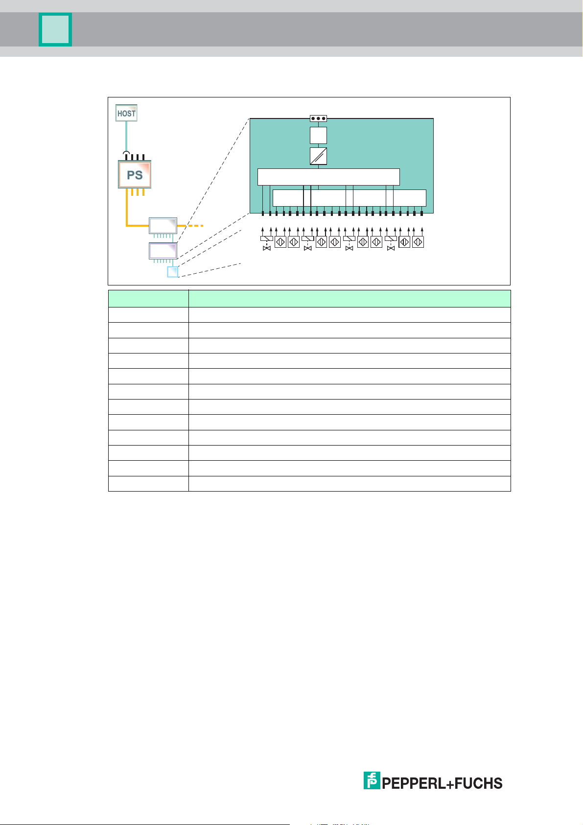
Valve Coupler Mode
Channel Valve Coupler Modes
1 Output 1, low-power valve
2 Position feedback sensor/switch A for output 1
3 Position feedback sensor/switch B for output 1
4 Output 2, low-power valve
5 Position feedback sensor/switch A for output 2
6 Position feedback sensor/switch B for output 2
7 Output 3, low-power valve
8 Position feedback sensor/switch A for output 3
9 Position feedback sensor/switch B for output 3
10 Output 4, low-power valve
11 Position feedback sensor/switch A for output 4
12 Position feedback sensor/switch B for output 4
8
2017-06
Page 9
Multi-Input/Output Device
MUX
Zone 1
-
+
S
MAU
µC
MUX
CH1
+ -
+ - + - + - + -
+ -
+ - + - + - + -
+ - + -
CH4 CH7 CH10
CH2 CH3 CH5 CH6 CH8 CH9 CH11 CH12
PI
FB/SP
Product Specifications
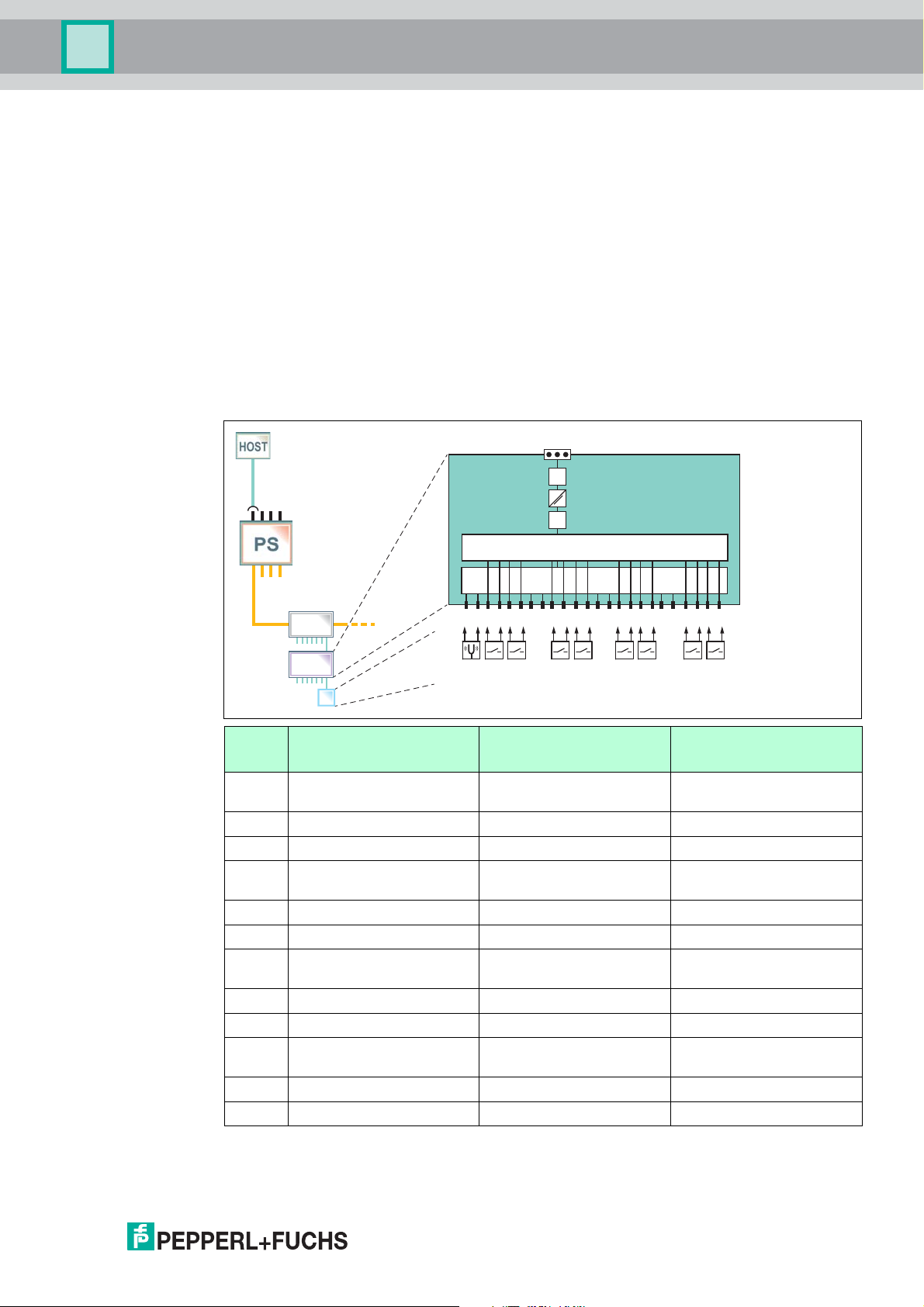
Binary Input Mode
The device samples the inputs in 2 independent cycles. Channels 1, 4, 7, and 10 are intended
to be used for sensing multiplexed binary inputs as vibrating forks, NAMUR sensors, or
mechanical switches. Channel 1 can also be configured to be used as a frequency or counter
input. If the channel 1 frequency or counter input is activated, channels 4, 7, and 10 are
deactivated. The ON-time of channel 1, 4, 7, and 10 can be adjusted individually between
10 ms ... 11 000 ms. The total cycle time is the sum of the 4 individual ON-times.
Channels 2, 3, 5, 6, 8, 9, 11, and 12 are intended to be used for sensing multiplexed binary
inputs as NAMUR sensors and mechanical switches. The sampling time of 10 ms is not
adjustable. The total cycle time is calculated as follows: number of used channels * 10 ms
(minimum 50 ms). If all 8 sensors are used, the total cycle time is 80 ms.
Refer to the technical data of the MIO for the specification of compatible sensors. A list of
compatible NAMUR sensors is available on the Pepperl+Fuchs website.
Sensor Input Mode (Including Frequency and Counter)
Chann
el
1 Vibration fork or
Sensor Input Modes Frequency Input Mode Counter Input Mode
Frequency input Counter input
sensor/switch
2 Sensor/switch Sensor/switch Sensor/switch
3 Sensor/switch Sensor/switch Sensor/switch
4 Vibration fork or
Disabled Disabled
sensor/switch
5 Sensor/switch Sensor/switch Sensor/switch
6 Sensor/switch Sensor/switch Sensor/switch
7 Vibration fork or
Disabled Disabled
sensor/switch
8 Sensor/switch Sensor/switch Sensor/switch
9 Sensor/switch Sensor/switch Sensor/switch
10 Vibration fork or
sensor/switch
Disabled Disabled
11 Sensor/switch Sensor/switch Sensor/switch
12 Sensor/switch Sensor/switch Sensor/switch
2017-06
9
Page 10

Multi-Input/Output Device
Product Specifications
Frequency or Counter Input Mode
Hardware channel 1 can be configured to be used as frequency or counter. If hardware
channel 1 is configured as frequency or counter input, the hardware channels 4, 7, and 10 are
deactivated.
The hardware channels 2, 3, 5, 6, 8, 9, 11, and 12 provide binary inputs as described in the
section "Binary Input Mode".
2.3 Hazardous Area Installation and Use
The device may be operated in Zone 1.
For applications in Zone 1, the type of protection must be Ex i according to Entity or FISCO.
The device may be installed in Zone 2.
The type of protection for the trunk interface is Ex ec or Ex ic according to Entity or FISCO.
Independent of the type of protection of the fieldbus interface, the inputs/outputs remain
intrinsically safe and may be installed in Zone 1.
Zone 2
Danger!
Explosion hazard from live wiring of non-intrinsically safe circuits
If you connect or disconnect energized non-intrinsically safe circuits in a potentially explosive
atmosphere, sparks can ignite the surrounding atmosphere.
Only connect or disconnect energized non-intrinsically safe circuits in the absence of a
potentially explosive atmosphere.
Type of Protection "Ex i"
Danger!
Explosion hazard from wrong separation distances
Non-observance of the separation distances between circuits can result in added currents or
voltages. This can result in a current/voltage flashover generating sparks. The sparks can ignite
the surrounding potentially explosive atmosphere.
Ensure you observe the compliance of the separation distances according to
IEC/EN 60079–14.
Danger!
Explosion hazard from wrong calculation of verification of intrinsic safety
If you do not consider the maximum permissible peak values of all components when
connecting intrinsically safe devices with intrinsically safe circuits of associated apparatus, this
can lead to added currents or voltages. This, in return, can result in a current/voltage flashover
generating sparks. The sparks can ignite the surrounding potentially explosive atmosphere.
10
Ensure you observe IEC/EN 60079-14 and IEC/EN 60079-25 for the verification of intrinsic
safety.
2017-06
Page 11
Multi-Input/Output Device
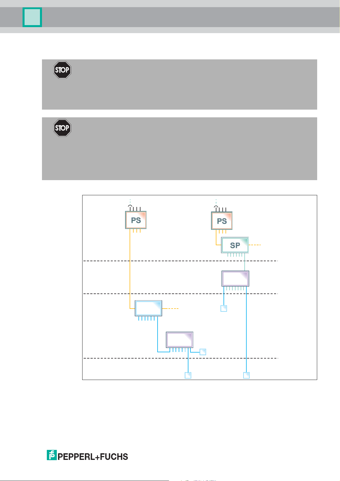
Zones 2, 22
Zone 0
Zones 1, 21
Non-Explosion
Hazardous
Area
Ex ic FISCO/
Ex ec
Ex i
Ex ia
FISCO
PI
*MIO-Ex12*
PI
*MIO-Ex12*
FB
Product Specifications
Type of Protection "Ex ec"
Danger!
Explosion hazard from pollution
An excessively polluted surface of the device can become conductive and consequently ignite
a surrounding potentially explosive atmosphere.
Ensure that you install the device only in environments with a pollution degree 2 or better
according to IEC/EN 60664–1.
Danger!
Explosion hazard from exposure to potentially explosive gas atmosphere
If the device is installed in Zone 2 without mounting it in a sufficiently suitable enclosure, gas,
dust, water or other external interferences can cause the live device to spark. The sparks can
ignite the surrounding potentially explosive atmosphere.
Only mount the device in an enclosure with degree of protection IP54 according to
IEC/EN 60529. The enclosure must have an EU declaration of conformity according to the
ATEX Directive for at least equipment category 3G.
Hazardous Area Installation Options
Figure 2.1 Installation options for the multi-input/output device in the hazardous area
Observe the EC-type-examination certificate or the statement of conformity. Pay particular
attention to any "special conditions" that may be indicated.
2017-06
11
Page 12
Multi-Input/Output Device
2
3
4
1
Installation and Commissioning
3 Installation and Commissioning
In the following section you find information on how to install and commission the multiinput/output (MIO) device in your fieldbus topology.
Danger!
Danger to life from using damaged or repaired devices.
Using a defective or repaired device can compromise its function and its electrical safety.
■ Do not use a damaged or polluted device.
■ The device must not be repaired, changed or manipulated.
■ If there is a defect, always replace the device with an original device from Pepperl+Fuchs.
Danger!
Explosion hazard from damaged electronic components
Premature wear of electronic components in a device that was previously used in a general
electrical installation can cause sparks that can ignite the surrounding potentially explosive
atmosphere.
Never install devices that have already been operated in general electrical installations in
electrical installations used in combination with hazardous areas!
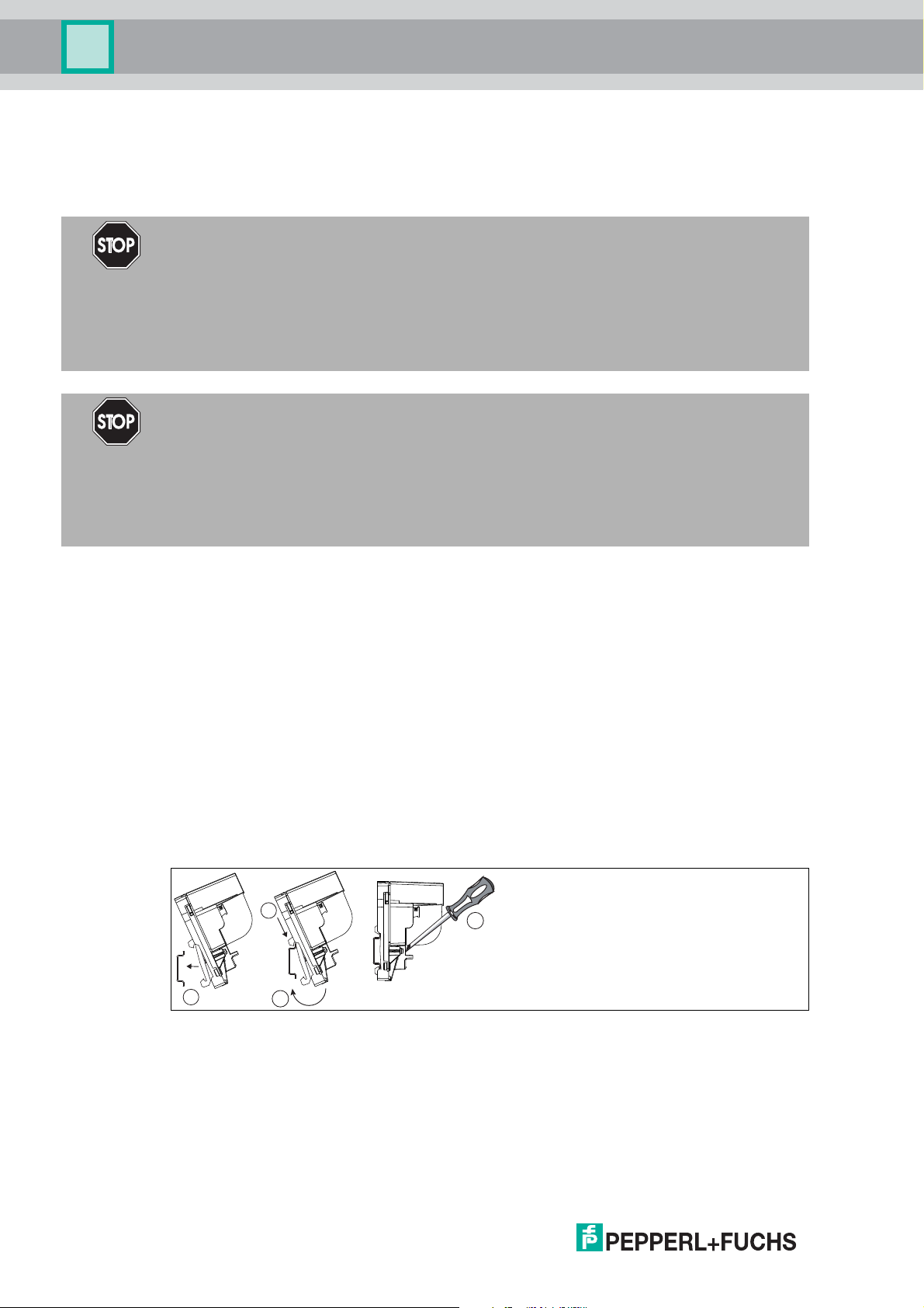
3.1 Mounting and Dismounting
Mounting/Dismounting F2D0-MIO*
F2D0-MIO* is designed for panel (wall) mounting.
■ Select mounting material that is suitable for the sub-surface (the wall).
■ Ensure that the mounting material guarantees secure fastening.
■ To attach the device: use 2 fixing screws with a diameter of 6 mm.
■ To dismount the device: Undo the fixing screws and take the device off the wall.
Mounting/Dismounting R8D0-MIO*
R8D0-MIO* is designed for mounting on a 35 mm DIN mounting rail in accordance with
EN 50022.
Mounting the R8D0-MIO* Electronics onto the DIN Mounting Rail
1 Place the R8D0-MIO* on the DIN mounting rail.
2 Use the top hook in order to hook the electronics onto the DIN mounting rail.
3 Move the bottom hook over the lower end of the DIN mounting rail.
4 Tighten the 2 fastening screws to attach the electronics on the DIN mounting rail.
Tightening torque: 0.4 Nm
To dismount the device: Take off the device in reverse order.
2017-06
12
Page 13

Multi-Input/Output Device
Installation and Commissioning
R8D0-MIO* Installation
Depending on the application, the R8D0-MIO* must be mounted in a suitable environment.
If mounted in Zone 2 for an Ex ec application, the environment (housing or enclosure) must
ensure the following:
■ IP54 in accordance with IEC 60529 for hazardous area Zone 2
■ Pollution degree 2 or better according to IEC/EN 60664-1
3.2 Hardware Installation
3.2.1 R8D0-MIO* Cable and Connection Information
Danger!
Explosion hazard from insufficient insulation
Insufficient dielectric strength of insulators between intrinsically safe circuits may lead to
interferences and to charge transfers that cause sparks. These sparks can ignite a potentially
explosive atmosphere.
Ensure that the dielectric strength of the insulation between intrinsically safe circuits is at least
500 V according to IEC/EN 60079–14.
Danger!
Explosion hazard or danger to life from inadequate installation of cables and connection lines
If you do not install cables and connection lines according to the instructions given in the
instruction manual, this can generate sparks that can ignite the surrounding potentially
explosive atmosphere. Furthermore, insufficient installation practice can result in electric
shock.
Ensure you carry out any cable gland installations in accordance with the instructions given in
the instruction manual.
Danger!
Explosion hazard from connection damage
Manipulating connections outside of the specified ambient temperature range can lead to
material damage, resulting in an unwanted failure of the connection. This could result in an
increased explosion hazard in potentially explosive atmospheres.
Only manipulate connections in the specified ambient temperature range.
Temperature range: -5 C° ... +70 C°
Danger!
Danger to life from incorrect installation
Incorrect installation of cables and connection lines can compromise the function and the
electrical safety of the device.
■ Observe the permissible core cross section of the conductor.
■ When using stranded conductors, crimp wire end ferrules on the conductor ends.
■ Use only one conductor per terminal.
■ When installing the conductors the insulation must reach up to the terminal.
■ Observe the tightening torque of the terminal screws.
The following section describes the different connection details of the multi-input/output with
particular reference to the torques required for a safe installation.
2017-06
13
Page 14
Multi-Input/Output Device
Click!
−+S
Installation and Commissioning
For any terminal connections, observe the following cable and connection information.
Screw Terminals: Cable and Connection Information
■ Permissible core cross section:
• Screw terminals with flexible or rigid wires: 0.2 mm
■
Insulation stripping length: 7 mm
■ If you use stranded connectors: Crimp on wire end ferrules
■ Ensure that connectors are mechanically locked
■ Torque required for tightening terminal screws: 0.5 Nm ... 0.6 Nm
Spring Terminals: Cable and Connection Information
■ Permissible core cross section:
• Spring terminals with flexible or rigid wires: 0.5 mm
■
Insulation stripping length: 10 mm
■ Ensure that connectors are mechanically locked
■ Torque required for tightening terminal screws: 0.5 Nm ... 0.6 Nm
2
... 2.5 mm
2
... 2.5 mm
2
2
Tip
Double-check that the correct torques are used when un- and reinstalling the terminal during
wiring activities!
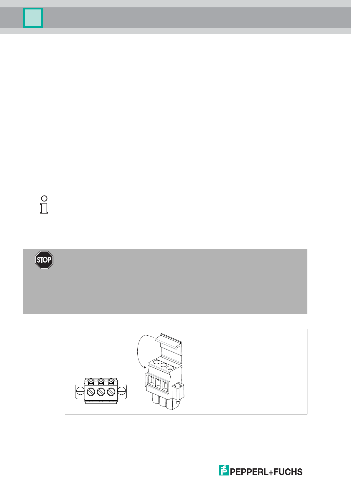
Connecting the Trunk
The multi-input/output is connected to the trunk line via designated screw or spring terminals.
Danger!
Explosion hazard from open or missing trunk terminal cover
If the device is installed Zone 2 and powered by a non-intrinsically safe power source, carrying
out hot work on the input/output terminals with an uncovered trunk terminal can lead to contact
with solid particles or tools. This can cause the live device to spark. The sparks can ignite the
surrounding potentially explosive atmosphere.
Ensure that the trunk terminal cover is present and correctly snapped onto the connector
housing to guarantee IP30 rating.
Trunk Connection with Covered Screw Terminal
14
+ Segment +
- Segment -
S Shield connection
2017-06
Page 15
Multi-Input/Output Device
−+S
+–
+–
+–
+–
+–
+–
Installation and Commissioning
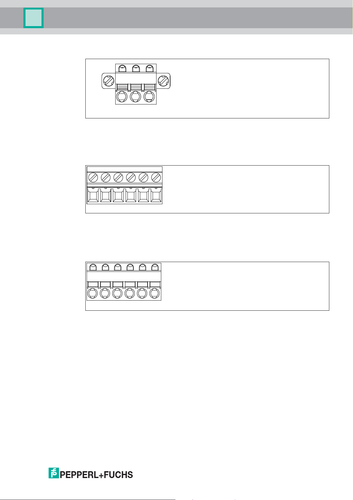
Trunk Connection with Spring Terminal
+ Segment +
- Segment -
S Shield connection
Multi-Input/Output Screw Terminal
6-pin screw terminal for multi-inputs/outputs
+ Input/output +
- Input/output -
Multi-Input/Output Spring Terminal
6-pin spring terminal for multi-inputs/outputs
+ Input/output +
- Input/output -
2017-06
15
Page 16
Multi-Input/Output Device
Installation and Commissioning
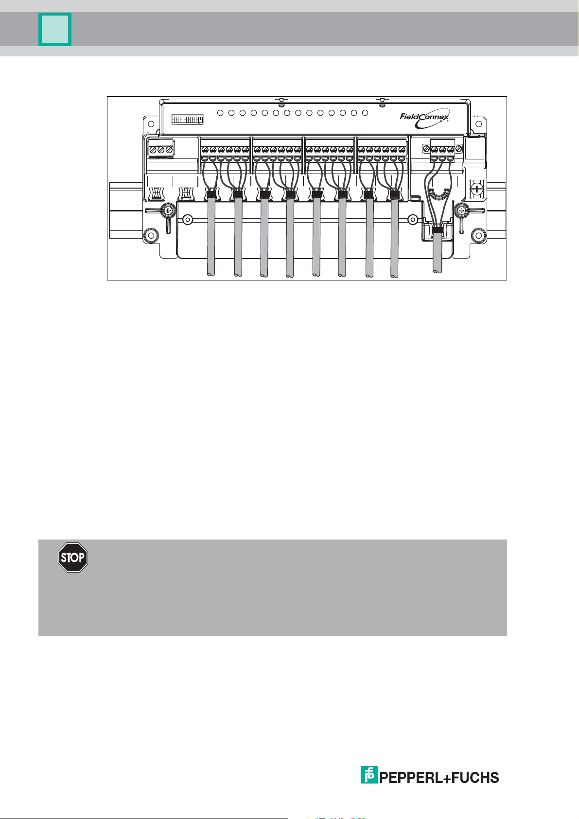
R8D0-MIO* Sample Connection Diagram
T G R
Extension
Configuration
ON
1 2 3 4 5 6 7 8
ERR
CH
+ -1+ -2+ -3+ -
3
21
4
5
4
7
6
+ -6+ -7+ -
+ -
5
891011 12
8
+ -
PWRCOM/
ERR
+ -
+ -
+ -
9
10
12
11
+ - S
Bus
The connection diagram shows the sample connection of the multi-input/output as a valve
coupler
Cable Position Fixture
The R8D0-MIO* electronics provides special fixtures for cable ties. To keep the cabling in a
safe position, use the fixtures with cable ties.
Cable tie width: up to 4 mm
Using Mechanical Switches
If mechanical contacts are used as valve final position feedbacks, observe the following. The
lead breakage and short circuit monitoring can be used after adding series and parallel
resistors in the lead. In this case the prerequisites are:
■ 1 x 1-kOhm series resistance for monitoring short circuit
■ 1 x 10-kOhm parallel resistance for lead breakage detection
3.2.2 F2 Housing Degree of Protection
The following section contains information concerning the installation and sealing of the cable
glands and the housing cover.
Danger!
Explosion hazard or danger to life from inadequate installation of cable glands
If you do not install cable glands according to the instructions given in the instruction manual,
this can generate sparks that can ignite the surrounding potentially explosive atmosphere.
Furthermore, insufficient installation practice can result in electric shock.
Ensure you carry out any cable gland installations in accordance with the instructions given in
the instruction manual.
Fixing the Housing Cover
Before closing the housing cover: Visually inspect the housing for any visible signs of damage
on the cover seal. If damaged, replace the seal with an original seal wear part.
16
Tightening torque for the screws of the housing cover: 2.5 Nm
2017-06
Page 17

Multi-Input/Output Device
Installation and Commissioning
General Information on the Installation of Cable Glands
When installing cable glands, observe the following:
■ Only insert permanently laid cables and wires into the cable glands.
• Ensure that the cables laid do not execute any strain on the cable glands.
• For permissible cable diameters, refer to the respective datasheet.
■ Use an appropriate strain relief clamp, e.g., a suitable cable clamp.
■ Seal unused cable glands with a suitable plug or replace them with appropriate screw
plugs. Observe the required degree of protection IP66.
• For a choice of stop plugs and screw plugs, refer to the respective datasheets.
• Note that the ambient temperature range can be restricted by the stopping plug.
■ Protect plastic cable glands against mechanical hazard.
■ Ensure you use the correct tightening torques when installing cable glands or plugs. For
detail see tables with torque information below.
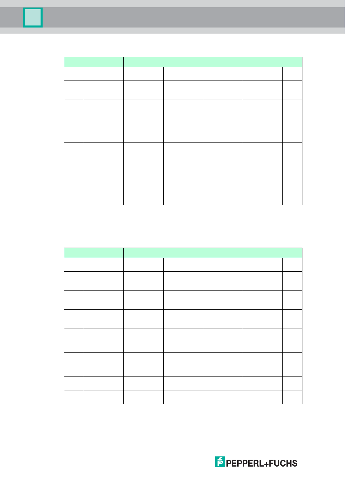
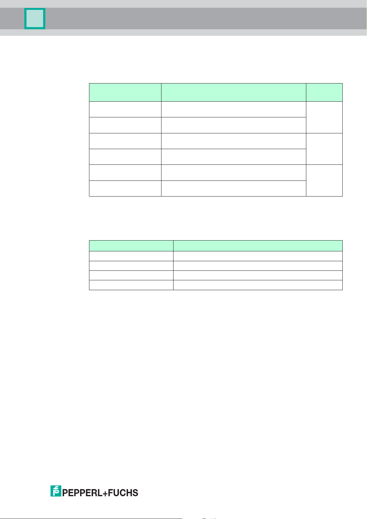
The specific technical data may vary depending on the type of cable gland or plug you use for
your installation. The following cable glands or plug types are documented and information is
available at www.pepperl-fuchs.com:
Cable Entry Option Cable Gland or Plug Type
00 Sealing plug plastic:
1 x M20,
8 x M16
SP.PE.M20.PA.C
SP.PE.M16.PA.C
01 Sealing plug stainless steel:
1 x M20,
8 x M16
SP.MD.M20.SS.C
SP.MD.M16.SS.C
02 Cable glands plastic:
1 x M20,
8 x M16
CG.PEDS.M20.PA.C.10
CG.PIDS.M16S.PA.C.10
03 Cable glands nickel plated brass:
1 x M20,
8 x M16
CG.NA.M20S.BN.C
CG.NA.M16.BN.C
04 Cable glands stainless steel:
1 x M20,
8 x M16
CG.NA.M20S.SS.C
CG.NA.M16.SS.C
05 Cable glands plastic
5 x M20 CG.PEDS.M20.PA.C.10
CG.PIDS.M20.PA.C.10
SP.PE.M20.PA.C
2017-06
17
Page 18
Multi-Input/Output Device
Installation and Commissioning
F2D0-MIO* Input/Output Cable Glands
Sensor Entries Clamping Ranges: Torques
Cable Entry Option CG or Plug
00 1 x M20, 8 x
M16 sealing
plug plastic
01 1 x M20, 8 x
M16 sealing
plug stainless
steel
02 1 x M20, 8 x
M16 cable
glands plastic
03 1 x M20, 8 x
M16 cable
glands nickel
plated brass
04 1 x M20, 8 x
M16 cable
glands stainless
steel
05 5 x M20 cable
glands plastic
Table 3.1 The torques that are actually required depend on the clamping range. This range is
determined by the diameter of the cable and the resulting seal combinations (S1+S2+S3,
S1+S2, S1) used with the cable gland or plug. For details see the documentation on the
cable gland or plug type available at www.pepperl-fuchs.com.
Ty p e
SP.PE.M16.PA.C- - - 1.5 Nm
SP.MD.M16.SS.C- - - 4 Nm
CG.PIDS.M16S
.PA.C.10
CG.NA.M16.BN
.C
CG.NA.M16.SS
.C
CG.PIDS.M20.
PA .C . 10
S1+S2+S3 S1+S2 S1 Body
- 4 … 5 mm:
4 … 6 mm:
20 Nm
4 … 6 mm:
20 Nm
- 6 … 8.5 mm:
3.5 Nm
6 … 9 mm:
18 Nm
6 … 9 mm:
18 Nm
5 Nm
5 … 8 mm:
4 Nm
9 … 12 mm:
15 Nm
9 … 12 mm:
15 Nm
7 … 12 mm:
5 Nm
1.5 Nm
4 Nm
4 Nm
2 Nm
F2D0-MIO* Fieldbus Cable Gland
Fieldbus Entries Clamping Ranges: Torques
Cable Entry Option CG or Plug
00 1 x M20, 8 x
M16 blind plug
plastic
01 1 x M20, 8 x
M16 blind plug
stainless steel
02 1 x M20, 8 x
M16 cable
glands plastic
03 1 x M20, 8 x
M16 cable
glands nickel
plated brass
04 1 x M20, 8 x
M16 cable
glands stainless
steel
05 5 x M20 cable
glands plastic
05 5 x M20 cable
glands plastic
Table 3.2 The torques that are actually required depend on the clamping range. This range is
determined by the diameter of the cable and the resulting seal combinations (S1+S2+S3,
S1+S2, S1) used with the cable gland or plug. For details see the documentation on the
cable gland or plug type available at www.pepperl-fuchs.com.
Ty p e
SP.PE.M20.PA.C- - - 2 Nm
SP.MD.M20.SS.C- - - 5.5 Nm
CG.PEDS.M20.
PA .C . 10
CG.NA.M20S.B
N.C
CG.NA.M20S.S
S.C
CG.PEDS.M20.
PA .C . 10
SP.PE.M20.PA.CUnused thread 2 Nm
S1+S2+S3 S1+S2 S1 Body
- 6 … 8.5 mm:
4 … 6 mm:
20 Nm
4 … 6 mm:
20 Nm
- 6 … 8.5 mm:
5 Nm
6 … 9 mm:
18 Nm
6 … 9 mm:
18 Nm
5 Nm
7 … 12 mm:
5 Nm
9 … 12 mm:
15 Nm
9 … 12 mm:
15 Nm
7 … 12 mm:
5 Nm
2 Nm
5.5 Nm
5.5 Nm
2 Nm
18
2017-06
Page 19

Multi-Input/Output Device
Installation and Commissioning
Note!
Careful when tightening cap nuts!
■ The cap nuts must be securely tightened. Tightening the cap nuts too much or not enough
both can affect the degree of protection.
■ The tightening torques of cap nuts vary, depending on the cable type used. For exact
details refer to the documentation of your cable manufacturer.
3.2.3 Grounding and Shielding
Equipotential Bonding of Devices in F2* Metal Housings
For electronic components in F2* metal housings in hazardous areas, suitable equipotential
bonding in accordance with IEC/EN 60079 is required. Therefore, the device is designed as
follows:
■ The shield (terminal S) of the intrinsically safe fieldbus trunk is internally connected to the
F2* metal housing.
■ The housing has a grounding point with a grounding screw. The grounding connection
must be secured against loosening and corrosion, e. g., by using tinned cable plates.
Note!
Ensure potential equalization of F2 Metal Housings
Ensure that the housing is connected properly to the potential equalization.
2017-06
19
Page 20

Multi-Input/Output Device
Installation and Commissioning
Shielding of the Fieldbus Trunk Using the R* Electronic Component in
Intrinsically Safe Segments
The shield (terminal S) of the fieldbus trunk is internally connected to the grounding point.
Grounding and Shielding *D0-MIO-Ex12*
Shielded cables for the valve or sensor are not required.
The device provides a grounding terminal for connecting to an equipotential bonding.
F2D0-MIO-Ex12* Grounding Points
R8D0-MIO-Ex12* Grounding Point
Connection to Equipotential Bonding System
Caution!
Risk of electric shock or property damage from inadequate grounding
If you fail to connect all metal parts of the device to protective local earth correctly, this could
result in potential equalization currents. These currents could hurt operating personnel or
cause property damage.
20
The grounding terminal is not a safety earth: Do not use the grounding terminal to ground
exposed metal parts.
Ground exposed metal parts of the device separately. Ensure that a correct grounding is
guaranteed at all times.
2017-06
Page 21

Multi-Input/Output Device
Installation and Commissioning
All shield connections are internally connected to the "Shield/Screen GND" grounding terminal.
Connecting the Ground Connection Cable
Note!
Use a cable with a minimum cross section of 4 mm².
1. Connect the ground cable to a cable lug.
2. Position the cable lug over the grounding terminal with the cable pointing downwards.
3. Screw the cable lug to the grounding terminal with 2 toothed lock washers inserted between
screw, lug, and terminal as illustrated:
1
2
3
2
4
Figure 3.1 Connecting the ground connection cable
1 Screw
2 Toothed lock washer
3 Cable lug
4 Grounding terminal on motherboard
4. Tighten the screw with a torque of 1.5 Nm.
The cable lug is properly attached and cannot come loose.
Connect the "Shield/Screen GND" grounding terminal to an equipotential bonding system.
2017-06
21
Page 22

Multi-Input/Output Device
Installation and Commissioning
3.2.4 Dip Switch Settings
You can use the DIP switches of the device in order to enable or disable the simulation and the
hardware write protection.
Hardware
write protection
Simulation
ON
OFF
123456 78
Figure 3.2 DIP switches to set the hardware write protection and simulation
The device has 8 DIP switches:
■ DIP switch S1: Simulation ON/OFF.
With activated simulation (ON), the valve position transferred from the transducer block to
the function block can be set by the control system independent from the actual valve
position.
■ DIP switch S2: Hardware write protection ON/OFF.
Parameterization of the device via the bus is no longer possible when write protection is
activated (ON).
■ DIP switch 3 ... 8: Unused
3.3 Firmware Download
The MIO supports firmware download according to FF-883 device download, class 2. In order
to enable the firmware download, set the resource block out of service (OoS).
During the firmware download, the MIO device does not operate its IO function and goes
through a reset, while activating the new firmware version.
Refer to your system software documentation for information on how to perform the firmware
download. If available, new firmware files can be downloaded from www.pepperl-fuchs.com.
22
2017-06
Page 23

Multi-Input/Output Device
Installation and Commissioning
3.4 Commissioning in Valve Coupler Mode
Danger!
Danger to life from unannounced operation of plant parts
During the initialization run, the valve is opened and closed once. Performing an initialization
run without explicit permission or having the plant in maintenance mode can pose personnel in
the plant at risk of coming into contact with hazardous substances or being exposed to
unexpected mechanical hazards.
Before starting the initialization run, ensure that you have permission/the plant is in
maintenance mode, so you do not endanger persons.
Caution!
Property damage from unannounced operation of plant parts
During the initialization run, the valve is opened and closed once. Performing an initialization
run without explicit permission or having the plant in maintenance mode can pose the plant at
risk of being damaged.
Before starting the initialization run, ensure that you have permission/the plant is in
maintenance mode.
When commissioning the MIO device in the valve coupler mode, a transducer block is
parameterized in 2 steps.
2017-06
23
Page 24

Multi-Input/Output Device
Installation and Commissioning
Setup Wizard Manual Configuration
Start wizard
Start commissioning
Read manual
Enter drive design:
Actuator Fail Action
Enter drive design:
Actuator Fail Action
Activate time monitoring
Step 1
(optional)
Start initialization run
Select target mode
Step 2
Set final position
feedback parameters
Select target mode
PV_D Generation
Monitoring and diagnosis functions:
- Time monitoring
- Cyclic functional check
- Lead monitoring of valve
- Lead monitoring of sensor
- Stroke counter
24
Enter additional data for
valve, drive, and valve control system
Commissioning complete
Figure 3.3 Flowchart for valve coupler commissioning
2017-06
Page 25

Multi-Input/Output Device
Installation and Commissioning
Note!
Implementing the Setup Wizard
The setup wizard is executed in the device description as a method. Refer to the
documentation of the control system in use for information on how to start this method. For the
use of the setup wizard, we recommend you also read the procedure for manual configuration.
Valve Coupler Mode Commissioning - Step 1
Set parameters in order to describe the valve used and connected position feedback sensors
(PFCs). Select whether to perform the parameterization manually or with the setup wizard.
1. Set the actuator fail action and PFC parameters manually use the wizard to assist you with
the following parameterization tasks:
• Selecting a valve drive design in the Act. Fail Action parameter.
• Initialization run: Automatic value determination for the Sensor Usage parameter
Note: During the initialization run, the valve is opened and closed once. Ensure, that
your plant is in maintenance mode, before starting the initialization run so you do not
endanger persons and tamper dangerously with the plant process.
• Activation of time monitoring of breakaway and transit times. In this case, the current
breakaway and running times of the valve are determined during the initialization run
and taken over as reference values. The maximum permitted deviation is set to
30 %.
2. Determine the "target mode" of the transducer block.
Parameterization Step 1 for Commissioning a Valve Coupler
Tra n s d u c e r Bl o c k
Step Description
1.1 Setting the valve design. Act. Fail Action See chapter 4.5.2
1.2 Automatic determination of the
sensor usage parameter.
1.3 Activation of time monitoring and
breakaway times.
1.4 Setting the target mode. TA RG E T_ M OD E See chapter 4.5.4
Parameters
Sensor Usage See chapter 4.5.3
Valve Monitoring See chapter 4.5.5
Further Information
Valve Coupler Mode Commissioning - Step 2
During the second step of parameterization, you can adapt the valve position information that
was transferred to the function block according to your requirements.
Prerequisite: Set the device in the mode Out of Service (OOS) in order to modify the PV_D
Ge n era t i on p ara m ete r .
You can activate the following diagnostic options:
■ Lead breakage or lead short circuit monitoring for the valve lead.
■ Lead breakage or short circuit monitoring for the PFC lead.
■ Cyclic functional test for the position "open" or "closed".
■ Stroke counter and limit value.
The diagnostic information can be stored in the MIO device via the connected valve and the
connected drive.
After having set all parameters, ensure that no "configuration error" is displayed in the
BLOCK_ERR parameter of the parameterized transducer block.
2017-06
25
Page 26

Multi-Input/Output Device
Installation and Commissioning
Parameterization Step 2 for Commissioning a Valve Coupler
Step Description
2.1 Sensor signals for the value
position feedback.
2.2 Diagnostic settings for lead
interruption or short circuit
monitoring.
2.3 Diagnostic settings the cyclic
function test.
2.4 Setting the stroke counter and
limit value.
More Information
For more information on diagnostic messages and alarms, see chapter 4.5.12.
For a detailed list of the messages of the tranducer block parameters and for troubleshooting,
see chapter 5.4.
Transducer Block
Parameters
PV_D Generation See chapter 4.5.3
Lead Fault Monitoring See chapter 4.5.8
Valve Monitoring See chapter 4.5.6
Valve Monitoring See chapter 4.5.7
Further Information
Tip
Test During Commissioning
During commissioning, you can perform function tests as follows: Set the DO function block to
the manual mode ("Man") and specify the reference value for the valve position directly via
OUT_D.
3.5 Commissioning in Binary Input Mode
In order to commission the MIO device in the binary input mode, parameterize the transducer
block parameters in the suggested order below.
Parameterization Steps for Commissioning a Binary Input
Step Description
1 Enable/disable hardware inputs 1,
4, 7, 10
2 Set sampling time hardware inputs
1, 4, 7, 10
3 Enable/disable hardware inputs 2,
5, 8, 11
4 Enable/disable hardware inputs 3,
6, 9, 12
5 Enable/disable lead fault
monitoring for all hardware inputs
6 Set fault state value for all
hardware inputs
7 Set information parameters of the
transducer blocks
Transducer Block
Parameters
Mode See chapter 4.6.2
Sensor On Time See chapter 6
Sensor A Mode See chapter 4.6.3
Sensor B Mode See chapter 4.6.3
Lead Fault Monitoring See chapter 4.6.4
Sensor Fault State See chapter 4.6.4
e. g., TAG_DESC See chapter 6
Further Information
3.6 Commissioning in Frequency or Counter Mode
In order to commission the MIO device in the frequency or counter mode, parameterize the
transducer block parameters in the suggested order below.
26
2017-06
Page 27

Multi-Input/Output Device
Installation and Commissioning
Parameterization Steps for Commissioning a Frequency Input or Counter
Step Description
1 Enable/disable hardware inputs 2,
5, 8, 11
2 Enable/disable hardware inputs 3,
6, 9, 12
3 Enable/disable lead fault
monitoring for all hardware inputs
1, 2, 3, 4, 8, 9, 11, 12
4 Set fault state value for hardware
inputs 2, 3, 5, 6, 8, 9, 11, 12
5 Set information parameters of the
transducer blocks
Tra n s d u c e r B l o c k
Parameters
Sensor A Mode See chapter 4.6.2
Sensor B Mode See chapter 4.6.3
Lead Fault Monitoring See chapter 4.6.4
Sensor Fault State See chapter 6
e. g., TAG_DESC See chapter 6
Further Information
2017-06
27
Page 28

Multi-Input/Output Device
Parameterization and Operation
4 Parameterization and Operation
The following section explains how to parameterize and operation the *D0-MIO-Ex12.FF
devices.
4.1 Introduction
The MIO FOUNDATION Fieldbus device supports 1 resource block, 4 transducer blocks, and
multiple function blocks. The I/O hardware channels are fixed assigned to the transducer
blocks.
Resource
Block
Function Block 1...4, DO
Function Block 5...16, DI
Function Block 17, AI
Function Block 18, MDO
Function Block 19...20, MDI
Communication
Stack
Physical Layer
Transducer Block 1
Transducer Block 2
Transducer Block 3
Transducer Block 4
4,5,6
1,2,3
Hardware Channels
7,8,9
10,11,12
FF-H1
Also, a "communication stack" is available that organizes the data exchange between the
fieldbus and the application. Depending on the mode of operation, a selection of instantiable
function blocks are available.
Function Block Overview
Function Block Type
Max. Number of Function
Blocks*
Default Number of Function
Blocks
DO, Discrete Output 4 4
DI, Discrete Input 12 2
AI, Analog Input 1 1
MDO, Multiple Discrete
1 1
Output
MDI, Multiple Discrete Input 2 2
Table 4.1 *The MIO device supports instantiable function blocks. Refer to your control system
documentation for information on how to instantiate function blocks.
28
2017-06
Page 29

Multi-Input/Output Device
Parameterization and Operation
The link between a specific function block and a transducer block is made by channel
reference.
4 different types of operation modes are available which are selectable with the resource block
parameter MIO_MODE:
Valve Coupler
In the valve coupler mode, 4 discrete output (DO) function blocks and 1 multiple discrete output
(MDO) function block can be used individually to establish a FOUNDATION Fieldbus
application.
A reference value is specified for the valve position and the current valve position feedback.
The reference value for the valve position is transferred to one of the transducer blocks. This
transducer block then controls the valve and reads back the current position via the position
feedback sensors (PFCs).
In addition, several diagnostic and monitoring functions for the valve can be activated in the
transducer blocks.
Binary Input
In the binary input mode, up to 12 discrete inputs are available. 12 discrete input function
blocks (DI) and 2 multiple discrete input (MDI) function blocks are available.
For 4 inputs, the sampling time is configurable, for the remaining 8, the sampling rate is fixed.
Diagnostic functions like lead short circuit and breakage can be activated in the transducer
blocks.
The position feedback input values can also be transmitted by using individual discrete input
function blocks (DI) or multiple input function blocks (MDI).
Frequency Input
In the frequency input mode, 1 frequency input and 8 discrete inputs are available. 1 analog
input (AI), 8 discrete inputs (DI), and 1 multiple discrete input (MDI) function block are
available.
Diagnostic functions like lead short circuit and breakage can be activated in the transducer
blocks.
Counter Input
In the counter input mode, 1 counter input and 8 discrete inputs are available. 1 analog input
(AI), 1 discrete output (DO) function block, 8 discrete input (DI) function blocks, and 1 multiple
discrete input (MDI) function block are available.
The DO function block allows you to reset the counter value.
The diagnostic function lead breakage can be activated in the transducer blocks.
The following sections are focused on the commissioning of the transducer blocks and their
interaction with the function blocks and the resource block. Representation and commissioning
of the function blocks and resource block are specific to the control system. Detailed
information can be found the documentation of the control system. This document includes a
concise list with the explanation of all parameters of the different types of blocks.
4.2 Prerequisites
To parameterize the MIO device, the associated device description (DD) must be included in
the engineering tool used. If you require to integrate the MIO device in the control system by
yourself, you find the necessary files on the Internet under www.pepperl-fuchs.com.
For detailed information on the import of the device description, refer to the documentation of
the the control system in use.
2017-06
29
Page 30

Multi-Input/Output Device
Parameterization and Operation
4.3 Device Identification
Each FOUNDATION Fieldbus device has a unique device ID. The device ID is structured as
follows for the MIO device:
Manufacturer Idenification Ty p e Serial Number
502B46
= Pepperl+Fuchs
These 3 identification fields are identically structured for all FOUNDATION Fieldbus MIO
devices. If several MIO devices are connected to one FF-H1 segment, these devices are
differentiated via their individual 14-digit serial numbers. The serial number is also provided on
a label attached to the device.
4.4 Commissioning Procedure
The MIO device supports different modes of operation as described. For more information, see
chapter 4.1.
Depending on the mode of operation you selected, adhere to the commissioning procedure
that applies for this mode.
0007
= Multi-Input/Output (MIO)
device
28583027543174
1. Read manual.
2. Start commissioning.
3. Set mode of operation MIO_MODE (resource block) to either one of the following modes:
1. Valve Coupler
2. Binary Input
3. Frequency Input
4. Counter Input
4. Complete commissioning.
4.5 Parameterization in Valve Coupler Mode
4.5.1 Interaction of Transducer Blocks and DO Function Blocks
In each of the DO function blocks, a reference value is calculated for the valve position in the
OUT_D parameter. This value is transferred to the transducer block that is connected with the
function block. A function block is connected to a transducer block through the Channel
function block parameter. This parameter contains the channel number 1 ... 4 of the transducer
block that the function block requires for interaction.
OUT_D of the function block can assume values from 0 ... 255. The value "0" means valve
"closed", values 0 mean valve "open".
Note!
Specifics of Reference Value
This specific reference value is contrary to many conventional devices where the value "0"
means "valve current OFF" and "1" means "valve current ON".
30
The transducer block accepts this reference value only if the status is GOOD (C) or
GOOD (NC). However, if the status is UNCERTAIN or BAD, the auxiliary valve is not controlled
electrically and the drive moves into the mechanical safety position.
If the current valve position is determined by 2 final position feedback sensors, the transducer
block transfers the current valve position back to the DO function block. The function block
represents the transferred value in the READBACK_D parameter. The numerical value
depends on the parameterization of the transducer block.
2017-06
Page 31

Multi-Input/Output Device
Parameterization and Operation
More Information
For more information on the paramterization of the transducer block, see chapter 4.5.3.
Function Blocks
DO Function Block
index 900
DO Function Block 1
CH=3 CH=0 CH=4
CH=1
Channel 1 - index 500
Transducer Block
Transducer Blocks
Figure 4.1 Interface of DO function block/transducer block
DO Function Block 3
index 950
Channel 2 - index 600
Transducer Block
index 1000
Channel 3 - index 700
DO Function Block 2
Transducer Block
index 1050
DO Function Block 4
Channel 4 - index 800
Transducer Block
OUT_D
Reference value
Transducer Block
READBACK_D
Primary value
Additional Diagnostic Information
In addition to the reference value for the valve position and the current valve position, also
diagnostic information is transferred between the function block and the transducer block.
Thus, it is possible to receive diagnostic messages from the transducer block also with control
systems which do not support alarms of transducer blocks.
For more information, see chapter 4.5.12.
Primary Value Parameter - Inversion and Behavior in Cyclic Transfer
The READBACK_D parameter is shown with the Primary Value parameter within the
DO function block. If the IO option "invert" is activated in the function block, the numerical value
is inverted. That means, a value of "0" becomes "1", a value 0 becomes "0".
If the current valve position is to be cyclically transferred to a control system or used in a
function block application, the value of the Primary Value parameter can be transferred to
BKCAL_OUT_D via the IO option "PV for BKCal_Out". If this option is not activated, the value
of BKCAL_OUT_D is only a copy of the current reference value.
4.5.2 Valve/Actuator Design
This section explains the setting options for the behavior of the valve or actuator with the Act.
Fail Action parameter, i.e., the actuator fail action.
Note that for setting this parameter, the target mode of the transducer block must be set to "Out
of Service" (OOS).
2017-06
31
Page 32

Multi-Input/Output Device
Parameterization and Operation
Actuator Drive Design with Act. Fail Action Parameter
The MIO device supports the 2 most frequent valve drive designs "self-opening" and "selfclosing". For choosing between these 2 options, the actuator drive and the control actuators
must be considered a unit. Self-opening and self-closing designate the behavior of the drive
when setting the electrical control system to "0". This is independent of the behavior of the
drive during a failure of the auxiliary power. The following values can be set:
■ Undefined
■ Self-opening
■ Self-closing
The value "undefined" is the default setting at the time of delivery. Setting the valve drive to a
defined state is required for the configuration of the MIO device. The transducer block leaves
the mode "Out of Service" only if 1 of the 2 options "self-opening" or "self-closing" is set.
Depending on the setting of the Act. Fail Action parameter, the transducer block determines
whether or not the connected auxiliary valve must be controlled electrically for starting a
position set by the function block.
Controlling a double-acting drive requires 2 channels, i. e., 2 DO function blocks and
2 transducer blocks.
4.5.3 Final Position Feedback
This section describes the options for parameterizing the final position feedback contact.
Prerequisite: Ensure that the Act. Fail Action parameter has a value assigned for the design of
the valve drive.
The response of the final position feedback contact is influenced by the following 2 parameters:
■ Sensor Usage parameter: Describes whether a final position feedback contact is
connected to the MIO device and how to evaluate its signals.
■ PV_D Generation parameter: If the signals of the final position feedback contacts are
evaluated, this parameter determines how to further process the evaluated signals prior to
transferring them to the function block.
Sensor Usage Parameter
The following settings are possible:
■ No position detection
■ Use sensor values for the Primary Value
■ Use options A ... D to determine the Sensor Usage parameter
No position detection
No final position feedback contact is connected to the MIO device. The current reference value
is returned as valve position to the function block.
32
Use sensor values for the Primary Value parameter
The 2 signals of the final position feedback contacts are transferred to the function block
without evaluation. The 2 binary signals are represented on bit 0 (position feedback contact A)
and bit 1 (position feedback contact B). Here, numerical values can be generated from 0 ... 3.
Possible problems are described in the next section PV_D Generation parameter.
Observe that the MIO device interprets a final position feedback contact signal as follows:
High current => logical 1
Low current => logical 0
2017-06
Page 33

Multi-Input/Output Device
Parameterization and Operation
A ... D Sensor Usage
When selecting one of the options A ... D, the transducer block determines from the position
feedback contact signals the position of the valve as "open", "closed", "intermediate" at that
moment. Whether an actuated sensor or activated mechanical contact represents an open or a
closed valve, depends on the design of the position feedback and the electrical characteristics
of the final position feedback contacts. A general representation is thus not possible.
Each of the 4 options corresponds to 1 set of combinations of the 2 final position feedback
contacts signals and the valve positions "open", "intermediate", and "closed". The following
4 tables show the signal combinations of final position feedback contact A and final position
feedback contact B assigned to a valve position for the options A ... D.
Sensor Usage A
Final Position
Feedback
Valve Position
Closed 0 1
Intermediate 0 0
Open 1 0
Uncertain 1 1
Contact A
Final Position
Feedback
Contact B
Sensor Usage B
Final Position
Feedback
Valve Position
Closed 1 0
Intermediate 1 1
Open 0 1
Uncertain 0 0
Sensor Usage C
Valve Position
Closed 1 0
Intermediate 0 0
Open 0 1
Uncertain 1 1
Sensor Usage D
Valve Position
Closed 0 1
Intermediate 1 1
Open 1 0
Uncertain 0 0
Contact A
Final Position
Feedback
Contact A
Final Position
Feedback
Contact A
Final Position
Feedback
Contact B
Final Position
Feedback
Contact B
Final Position
Feedback
Contact B
2017-06
33
Page 34

Multi-Input/Output Device
Parameterization and Operation
One of the options A ... D must be selected in order to make use of time monitoring, stroke
counter function, or cyclic functional tests.
The letter/number combinations after the options A ... D denote the signal input for the
positions:
■ O: open
■ I: intermediate
■ C: closed
The following table gives the assignment of the position feedback contact signals "0" and "1" to
the numerical values 0 ... 3:
Number
Position Feedback
Contact A
Position Feedback
Contact B
0 0 0
1 1 0
2 0 1
3 1 1
PV_D Generation Parameter
If you selected one option from A ... D for the Sensor Usage parameter, you can use the
PV_D Generation parameter to determine what to do with the evaluated signals prior to
transferring them to the function block. You can select one of the following options:
■ Val ve position
■ Valve position extended
■ Intermediate => Closed
■ Intermediate => Open
■ Intermediate => Next
■ Intermediate => Last (default)
Valve Position
The position of the valve is transferred to the function block as a numerical value:
34
Numerical Value Valve Pos ition
1 Closed
2 Open
3 Intermediate position
0 Unkown
2017-06
Page 35

Multi-Input/Output Device
Parameterization and Operation
Valve Position Extended
In the intermediate position of the valve, the information on the valve position is extended with
the information "opening" and "closing". This information is determined by the current control
process and need not coincide with the actual direction of travel (e. g., when changing the set
position while the valve is in the intermediate position).
Numerical Value Valve Po sition
1 Closed
2 Open
3 Intermediate position/opening
4 Intermediate position/closing
0 Unkown
The options "Valve Position" and "Valve Position Extended", and the setting "Use sensor values
for PV_D" in the Sensor Usage parameter are intricate to be used with the function block.
The transducer block transfers the valve position to the function block as part of the
READBACK_D parameter. From there, the valve position information is transferred to the
Primary Value parameter which can be cyclically transferred to a control system via
BKCAL_OUT_D. Alternatively, the valve position information can be used in a function block
application.
If an inversion is active in the function block, the numerical value "0" becomes "1" and all
numerical values 0 become "0". That means, all valid valve positions are inverted to "0".
Also, the IO options of the DO function block "SP-PV Track in LO" and "SP-PV Track in Man" do
no longer work because the range of values of the Primary Value parameter does not
correspond to that of SP_D.
In order to ensure a more straightforward use of the valve position information in the function
block, you can choose one of the following options.
These options show the valve position at the value range of the set position "closed" (0) or
"open" (1) and determine the position information to be issued in the intermediate position:
■ Intermediate => Closed: The intermediate position is always interpreted as "closed"
■ Intermediate => Open: The intermediate position is always interpreted as "open"
■ Intermediate => Next: During a closing process, the intermediate position is always
interpreted as "closed" and during an opening process as "open"
■ Intermediate => Last (default setting): During a closing process, the intermediate
position is interpreted as "open" and during an opening process as "closed"
The default setting "Intermediate => Last" has the effect that during an opening or closing
process, the last position is displayed until the valve has actually reached the reference
position. This is useful, e. g., for a sequential valve control when any further steps can only take
place after the valve has fully reached the desired position. In this case, only the reference
value must be compared with the feedback.
4.5.4 Target Mode
The "Target mode" determines the mode of operation of the MIO device. The modes of
operation are possible:
■ Out of service (OOS, default setting)
■ Auto
■ Manual (Man)
2017-06
35
Page 36

Multi-Input/Output Device
Parameterization and Operation
In OOS mode, the transducer block is deactivated and the valve output is not controlled. Thus,
a connected actuator drive moves in its mechanical safety position. Use this mode if you intend
to adjust basic function parameters, e. g., Act. Fail Action, Sensor Usage, and PV_D
Generation or if the corresponding channel is not used.
The "Auto" mode is provided for operation. The transducer block operates in this mode as
specified by parameterization.
"Man" is used by the setup wizard and must not be modified.
4.5.5 Time Monitoring
The MIO device can monitor the breakaway and transit times of a valve. You can activate the
time monitoring parameter to measure the breakaway and transit times of the connected valve.
You can compare the measured values to the reference values during each reference value
modification of the valve position.
If a measured time is longer or shorter than the reference time plus a specified tolerance, an
alarm is generated. The times measured last are also displayed.
Prerequisites
The following parameters must be set as a prerequisite for time monitoring:
■ Act. Fail Action. For more information, see chapter 4.5.2.
■ Sensor Usage. For more information, see chapter 4.5.3.
Activation of Time Monitoring
You can activate time monitoring by setting the option Time Monitoring in the Valve Monitoring
parameter.
36
2017-06
Page 37

Multi-Input/Output Device
Intermediate
position
Open
Closed
of valve
Setpoint
Val ve
position
12 34
Open
Closed
Parameterization and Operation
Reference Times
Enter the reference times for the 4 different monitoring times in seconds (s) during
commissioning. The breakaway and transit times are defined as follows:
Definition of Breakaway and Transit Times
1 = breakaway time closed->open
2 = transit time closed->open
3 = breakaway time open->closed
4 = transit time open->closed
Each reference value consists of the reference value in seconds (s) plus the maximum
admissible percentage deviation. If a measured time is shorter or longer than the specified
tolerance, an alarm is generated.
■ Reference value of breakaway times, value range: 0 s ... 60 s
■ Reference value of transit times, value range: 0 s ... 180 s
■ Max. deviation, value range: 0 % ... 100 %
The accuracy of time measurement is +/- 0.05 s
Note!
Time Monitoring with the Setup Wizard
When using the setup wizard, the reference parameters are set automatically:
■ The current time values of the valve are set as the reference times.
■ The maximum admissible deviation is set to 30 %. This tolerance can be adapted
separately for each time value as required.
2017-06
37
Page 38

Multi-Input/Output Device
Parameterization and Operation
4.5.6 Cyclic Function Test (Partial Stroke Test)
Prerequisites
The following parameters must be set as a prerequisite for the cyclic function test:
■ Act. Fail Action parameter. For more information, see chapter 4.5.2.
■ Sensor Usage parameter. For more information, see chapter 4.5.3.
■ Valve Monitoring parameter > Time Monitoring is activated. For more information, see
chapter 4.5.5.
"Cyclic Test Open" and "Cyclic Test Closed"
The MIO device provides a function check for the connected valve or actuator within an
adjustable period of time. This way, you can monitor valves or actuator that are rarely triggered
for faults. When active, the MIO device controls the valve or actuator contrary to the current
control until the breakaway point. Then, the MIO device controls the valve or actuator back into
the initial position.
The measured breakaway time is displayed as the last breakaway time measured, and falling
below or exceeding the admissible range of values generates an alarm.
Depending on the operation, the cyclic function test for the valve position "open" or "closed"
can be switched ON or OFF under the Valve Monitoring parameter.
Note that the time monitoring option must be activated in Valve Monitoring in order to use the
cyclic function test.
"Period Cyclic Test"
You can set a time interval for the cyclic function test. The interval can range between
10 seconds and 7 days, 23 hours, 59 minutes and 59 seconds. If the set valve position is not
modified after this time, the device automatically carries out a cyclic function test.
4.5.7 Stroke Counter
The MIO device can monitor the number of strokes of a valve.
In the Valve Monitoring parameter, use the Stroke Counter to activate this function.
A stroke starts in the valve status "open" and continues with a closing and opening procedure.
When activated, the Stroke Counter increases by 1, after the valve is closed and opened again.
This parameter can be initialized with a start value. The current count remains unaffected even
after a voltage failure.
Stroke Counter Limit
You can determine a count as the limit value for the counter function. If the count of the Stroke
Counter exceeds the stroke counter limit entered, the alarm "Maintenance needed now“ is
generated. No alarm is given if the stroke counter limit is 0. This way, you can count the number
of strokes without releasing an alarm for a limit value.
38
2017-06
Page 39
Multi-Input/Output Device
Parameterization and Operation
4.5.8 Lead Breakage and Lead Short Circuit Monitoring
You can independently enable or disable lead short circuit and lead breakage monitoring of the
valve and position feedback sensors. Use the Lead Fault Monitoring parameter to achieve this.
Option Description
Short Circuit Sensor-A Enable/disable lead short circuit detection for final
position feedback sensor A connection
Lead Breakage Sensor-A Enable/disable lead breakage detection for final
position feedback sensor A connection
Short Circuit Sensor-B Enable/disable lead short circuit detection for final
position feedback sensor B connection
Lead Breakage Sensor-B Enable/disable lead breakage detection for final
position feedback sensor B connection
Short Circuit Valve Enable/disable lead short circuit detection for valve
connection
Lead Breakage Valve Enable/disable lead breakage detection for valve
connection
Hardware
Channels
TB1: 2
TB2: 5
TB3: 8
TB4: 11
TB1: 3
TB2: 6
TB3: 9
TB4: 12
TB1: 1
TB2: 4
TB3: 7
TB4: 10
The Lead Fault parameter contains the fault status of the valve and sensor connection.
Structure and content is identical to the Lead Fault Monitoring parameter.
The Sensor Fault State parameter defines the process value handling of position feedback
sensors in case of a lead fault.
Option Description
Set Fault State to Sensor A Enable/disable fault handling of position feedback sensor A
Sensor A Fault State Fault value of position feedback sensor A
Set Fault State to Sensor B Enable/disable fault handling of position feedback sensor B
Sensor B Fault State Fault value of position feedback sensor B
4.5.9 Valve and Drive Information
You can enter information of the valve drive or transducer block in the following parameters.
The first 3 parameters are part of all FOUNDATION Fieldbus blocks. Their use depends on the
control system.
■ Strategy: Identify grouped blocks by entering a number. This number is not controlled or
used by the block.
■ Alert Key: Identification number for the plant unit which is used by the master computer to
sort, e. g., alarm or operation messages. Values from 0 ... 65535 are valid.
■ Tag Desc.: Description of the task of the TB.
■ Act. Man.: Mechanical drive manufacturer
■ Act. Model: Mechanical drive model
■ Act. Ser. Num.: Mechanical drive serial number
■ Valve Man.: Valve manufacturer
■ Valve ID: Valve model
■ Valve Type: undefined, linear, turning, other
■ Valve Ser. Num.: Valve serial number
2017-06
39
Page 40

Multi-Input/Output Device
Parameterization and Operation
4.5.10 Final Value as Valve Reference Value
The reference value for the valve position and the associated status are issued in the Final
Value parameter. The Final Value is a copy of the OUT_D value of the DO function block
connected with the transducer block. This reference value can assume the values "closed" (0)
or "open" ( 0).
The value is accepted only with a status GOOD-NonCascade or GOOD-Cascade. If the status
is BAD or UNCERTAIN, the connected auxiliary valve is not controlled electrically, so that the
associated drive moves into the mechanical safety position.
4.5.11 Valve Position
The signals recorded by a connected final position feedback contact are indicated in several
parameters of different significance.
Sensor Value A or Sensor Value B Parameter
These parameters display the input signal of final position feedback contact A or final position
feedback contact B. The MIO device interprets a final position feedback contact signal as
follows:
high current => logical 1
low current => logical 0
Valve Posi tion Parameter
The current valve position "open", "intermediate", or "closed" is displayed as value. By setting
the Sensor Usage parameter accordingly, the signals of the final position feedback contacts
are assigned a definite position.
For more information, see chapter 4.5.3.
Valve Position Extended Parameter
In the intermediate valve position, the information in the valve position parameter is extended
by the information "opening" and "closing". This information is determined by the current
control process and need not coincide with the actual direction of travel - i. e., when changing
the set position while the valve is in the intermediate position.
Primary Value Parameter
This parameter issues the value which is fed back as valve position to the assigned function
block. The Primary Value parameter is an unsigned 8 with the status which is displayed in the
function block as READBACK_D. Which information is issued at which value range in the
Primary Value parameter depends on how you set the Sensor Usage and PV_D Generation
parameters.
For more information, see chapter 4.5.3.
Valve Info Parameter
This parameter displays information of the current status of the valve or transducer block. This
includes the following information:
40
■ Stroke counter limit exceeded
■ Cyclic function test running
■ Actuation - The valve has not yet reached the new final position after having changed the
reference value.
2017-06
Page 41

Multi-Input/Output Device
Parameterization and Operation
4.5.12 Diagnostic Messages and Alarms
The MIO device features several diagnostic options.
If a fault occurs, the transducer block sets a block alarm. The block alarm is a combined error
signal for all fault signals and remains set, as long as a fault in the block exists. For detailed
information of the alarm cause after a block alarm, the MIO device provides the following
parameters:
■ Block Err.
■ XD Error
■ Valve Lead Fault
■ Sensor Lead Fault
■ Valve Warning
■ Valve Error
■ Val ve Info
If the control system in use supports alarm messages via the FOUNDATION Fieldbus, setting
and resetting of the block alarm is transferred via the bus to the control system. As this function
is currently not supported by all control systems, the MIO device offers an alternative option to
issue faults:
As soon as the transducer block recognizes a fault, a message is set in Block Err. parameter of
the connected DO function block. Normally, this parameter is read out and evaluated in cycles
by control systems which do not support alarm messages via FOUNDATION Fieldbus.
If the fault is related to the valve control (e. g., lead breakage of valve feeding lead or exceeding
the admitted valve transit time), the message "Output failure" is set. If the final position
feedback contact fails (e. g., lead short circuit of the lead that feeds the final position feedback
contact), the message is "Input failure".
All messages, except a configuration error, are transferred this way. Therefore, check after each
modification of parameterization of the MIO device that this message is not set in the Block Err.
parameter. If the control system used does not support alarm messages via FOUNDATION
Fieldbus, in the Features Sel. resource block parameter, deactivate the option "Reports".
More Information
For more information on diagnostic options and troubleshooting, see chapter 5.
For a detailed list of the messages of the tranduceer block parameters and for
troubleshooting, see chapter 5.4.
4.6 Parameterization in Binary Input Mode
The binary mode supports up to 12 discrete inputs, organized in the following 2 groups:
■ Group 1: Hardware channels 1, 4, 7, 10
■ Group 2: Hardware channels 2, 3, 5, 6, 11, 12
The device samples the inputs in 2 independent cycles. Group 1 hardware channels 1, 4, 7, 10
are intended to be used for sensing multiplexed binary inputs as vibration forks, NAMUR
sensors, or mechanical switches. The ON-time of group 1 channels can be adjusted
individually in a range between 10 ms ... 11 000 ms. The total cycle time is the sum of the
4 individual ON-times.
Group 2 hardware channels 2, 3, 5, 6, 11, 12 are intended to be used for sensing multiplexed
binary inputs as NAMUR sensors and mechanical switches. The sampling time is fixed to
10 ms and is not adjustable. The total cycle time is the product of the number of channels used
x 10 ms. The minimum total cycle time is 50 ms. If all 8 sensors are used, the total cycle time is
80 ms.
2017-06
41
Page 42

Multi-Input/Output Device
Parameterization and Operation
4.6.1 Transducer Blocks Interacting with DI or MDI Function Blocks
For the discrete inputs, the hardware channels can be linked to function blocks in different
ways.
Using 12 Individual DI Function Blocks
Each discrete input is linked to the independent DI function blocks 5 … 17.
For group 1 hardware inputs, the transducer block channels 301 … 304 are used.
For group 2 hardware inputs, the channels 201 … 208 are used.
Tra n s d u c e r B l o c k Tra n s d u c e r C h a n n e l Hardware Input
1 301 1
201 2
202 3
2 302 4
203 5
204 6
3 303 7
205 8
206 9
4 304 10
207 11
208 12
Using 2 MDI Function Blocks
Group 1 hardware inputs are linked to an MDI by using channel number 300.
Group 2 hardware inputs are linked to an MDI using channel number 200.
Hardware Group Tr a n s d u c e r C h a n n e l Hardware Input
1 300 1,4,7,10
2 200 2,3,5,6,8,9,11,12
Using 2 DI Function Blocks
If required, you can use this option to increase the update time performance. Use the sensor
inputs with 2 DI function blocks to read the input states of the 2 hardware input groups.
Group 1 sensor inputs are linked to a DI by using channel number 305.
Group 2 sensor inputs are linked to a DI using channel number 5.
The input values are assigned to the respective bits of the FIELD_VAL_D parameter value of
the transducer blocks according to the following tables:
Group 1 Hardware Inputs
Bit Description
0 Sensor value hardware channel 1
1 Sensor value hardware channel 4
2 Sensor value hardware channel 7
42
2017-06
Page 43

Multi-Input/Output Device
Parameterization and Operation
Bit Description
3 Sensor value hardware channel 10
4 ... 7 not used
Group 2 Hardware Inputs
Bit Description
0 Sensor value hardware channel 2
1 Sensor value hardware channel 3
2 Sensor value hardware channel 5
3 Sensor value hardware channel 6
4 Sensor value hardware channel 8
5 Sensor value hardware channel 9
6 Sensor value hardware channel 11
7 Sensor value hardware channel 12
In the DI function block, the value of the FIELD_VAL_D parameter is assigned to the Primary
Value parameter, and from there, to the OUT_D parameter value. Thus, cyclic transmission of
the groups of sensor values to a control system is possible as well as their further use in a
function block application.
Because of the many inputs mapped to a single parameter, the status does not reflect the
status of a specific input any more. Failures, such as lead breakage or lead short circuit of the
sensor wires are no longer issued using the status. The status remains GOOD in all instances.
Only hardware failures of the MIO device are issued with the status BAD - Device Failure.
With the PV_FTIME parameter, you can determine for how long (in seconds) the final position
feedback sensor values have to be stable, before they are passed on from the FIELD_VSL_D
parameter to the Primary Value parameter.
Depending on the application used, sensor values can keep changing or influencing one
another. In this case, an inappropriate numeric value can result in the Primary Value parameter
not being updated at all. Therefore, Pepperl+Fuchs recommends setting the
PV_FTIME parameter to 0. If time monitoring is not necessary, Pepperl+Fuchs recommends
setting the Sensor Usage parameter to "Use sensor values for PV_D".
4.6.2 Enabling/Disabling Hardware Channels 1, 4, 7, 10
Use the Sensor Exe Mode parameter to individually enable or disable the channels 1, 4, 7, 10.
The Sensor On-Time parameter defines the time a specific hardware input is powered and
processed before the next hardware input is switched on.
Tra n s d u c e r B l o c k Hardware Channel
1 1
2 4
3 7
4 10
2017-06
43
Page 44

Multi-Input/Output Device
Parameterization and Operation
4.6.3 Enabling/Disabling Hardware Channels 2, 3, 5, 6, 8, 9, 11, 12
Use the Sensor A Mode and Sensor B Mode parameters to individually enable or disable the
channels 2, 3, 5, 6, 8, 9, 11, 12.
Tr an sd u c e r
Block
1 2 3
2 5 6
3 8 9
4 11 12
4.6.4 Lead Fault Monitoring
You can independently enable or disable lead short circuit and lead breakage monitoring of the
sensor connections with the Lead Fault Monitoring parameter.
Hardware Channel
Sensor A Mode Sensor B Mode
Option Description Hardware Inputs
Short Circuit Sensor-A Enable/disable lead short
circuit detection for position
feedback sensor –
sensor A connection
Lead Breakage Sensor-A Enable/disable lead breakage
detection for position
feedback sensor –
sensor A connection
Short Circuit Sensor-B Enable/disable lead short
circuit detection for position
feedback sensor –
sensor B connection
Lead Breakage Sensor-B Enable/disable lead breakage
detection for position
feedback sensor –
sensor B connection
Short Circuit Sensor Enable/disable lead short
circuit detection for sensor
connection
Lead Breakage Sensor Enable/disable lead breakage
detection for sensor
connection
The Lead Fault parameter contains the fault status of the sensor connection. Structure and
content is identical to the Lead Fault Monitoring parameter.
TB1: 2
TB2: 5
TB3: 8
TB4: 11
TB1: 3
TB2: 6
TB3: 9
TB4: 12
TB1: 1
TB2: 4
TB3: 7
TB4: 10
44
2017-06
Page 45
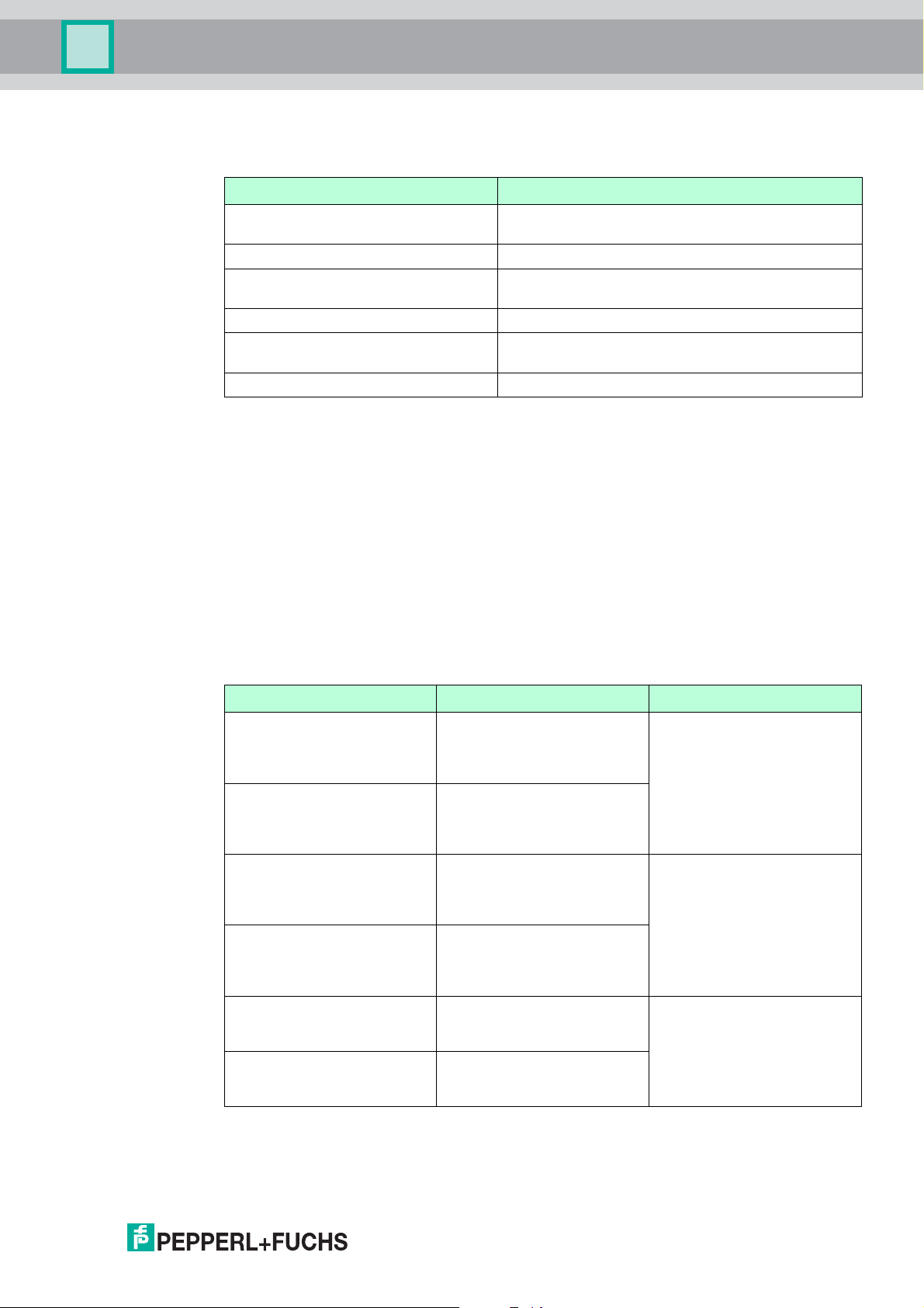
Multi-Input/Output Device
Parameterization and Operation
The Sensor Fault State parameter defines the process value handling of sensor inputs in case
of a lead fault.
Option Description
Set Fault State to Sensor A Enable/disable fault handling of position feedback
sensor A
Sensor A Fault State Fault value of position feedback sensor A
Set Fault State to Sensor B Enable/disable fault handling of position feedback
sensor B
Sensor B Fault State Fault value of position feedback sensor B
Set Fault State to Sensor Enable/disable lead short circuit detection for sensor
connection
Sensor Fault State Fault value of sensor connection
4.7 Parameterization in Frequency Mode
In the frequency mode, the hardware channel 1 or transducer block 1 is used. The hardware
channels 4, 7, 10 are disabled. The hardware channels 2, 3, 5, 6, 8, 9, 11, 12 can be handled
as described in the binary mode section.
4.7.1 Interaction of the Transducer Blocks and AI Function Blocks
The hardware channel 1 frequency input is linked to an AI function block by using channel
number 400. The frequency value is provided by the transducer block 1 via the FREQ
parameter. The XD_SCALE parameter supports “Hz” as unit.
4.7.2 Lead Fault Monitoring
You can independently enable or disable lead short circuit and lead breakage monitoring of the
sensor connections with the Lead Fault Monitoring parameter.
Option Description Hardware Inputs
Short Circuit Sensor-A Enable/disable lead short
circuit detection for position
feedback sensor –
sensor A connection
Lead Breakage Sensor-A Enable/disable lead breakage
detection for position
feedback sensor –
sensor A connection
Short Circuit Sensor-B Enable/disable lead short
circuit detection for position
feedback sensor –
sensor B connection
Lead Breakage Sensor-B Enable/disable lead breakage
detection for position
feedback sensor –
sensor B connection
Short Circuit Sensor Enable/disable lead short
circuit detection for sensor
connection
Lead Breakage Sensor Enable/disable lead breakage
detection for sensor
connection
TB1: 2
TB2: 5
TB3: 8
TB4: 11
TB1: 3
TB2: 6
TB3: 9
TB4: 12
TB1: 1
The Lead Fault parameter contains the fault status of the sensor connection. Structure and
content is identical to the Lead Fault Monitoring parameter.
2017-06
45
Page 46

Multi-Input/Output Device
Parameterization and Operation
The Sensor Fault State parameter defines the process value handling of sensor inputs in case
of a lead fault.
Option Description
Set Fault State to Sensor A Enable/disable fault handling of position feedback
sensor A
Sensor A Fault State Fault value of position feedback sensor A
Set Fault State to Sensor B Enable/disable fault handling of position feedback
sensor B
Sensor B Fault State Fault value of position feedback sensor B
4.8 Parameterization in Counter Mode
In the counter mode, the hardware channel 1 or transducer block 1 is used. The hardware
channels 4, 7, and 10 are disabled. The counter value can be either linked to an AI function
block as a float value or to a DI function block as an unsigned 8 value. The hardware
channels 2, 3, 5, 6, 8, 9, 11, and 12 can be handled as described in the sensor mode section.
One DO function block serves for resetting the counter value to 0.
4.8.1 Interaction of the Transducer Blocks and AI, DO Function Blocks
The hardware channel 1 counter input is linked to an AI function block by using channel
number 400. To reset the counter value, a DO is available which is linked to the transducer
block by using channel number 500. The hardware channels 2, 3, 5, 6, 8, 9, 11, and 12 can be
handled as described in the sensor mode section.
The counter value is provided by the transducer block 1 via the CNTR_VALUE_D parameter.
The FINAL_VALUE_D transducer block parameter contains the actual counter reset state.
4.8.2 Interaction of the Transducer Blocks and DI, DO Function Blocks
The counter value can be mapped as an unsigned 8 bit value to a DI function block using
channel number 401. If the counter value exceeds 255, the HI_LIMIT status is set. To reset the
counter value, a DO is available which is linked to the transducer block by using channel
number 500. The hardware channels 2, 3, 5, 6, 8, 9, 11, and 12 can be handled as described
in the sensor mode section.
4.8.3 Lead Fault Monitoring
In counter mode, no lead short circuit monitoring is supported.
46
2017-06
Page 47
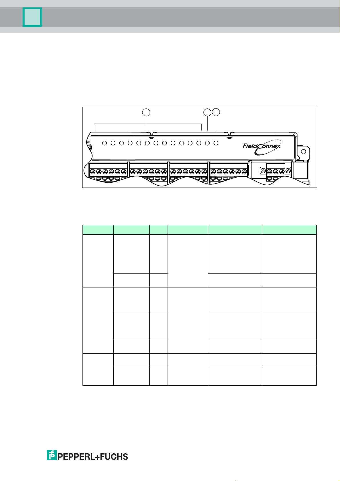
Multi-Input/Output Device
Troubleshooting and Diagnosis
5 Troubleshooting and Diagnosis
The following information helps you to identify problems with the multi-input/output device and
interpret diagnostic issues.
5.1 LED Status and Error Indication
The device is providing LED indication for each channel, the communication status and the
fieldbus voltage.
123
ERR
CH
3
21
5
7
4
6
891011 12
ERR
PWRCOM/
1 LED CH ERR 1 ... 12 for indicating channel errors
2 LED COM ERR for indicating communication errors
3 LED PWR for indicating operation
LED Indication Color Information Reason Remedy
CH ERR Flashing Red Status of the
corresponding
channel
OFF -- Channel works as
COM ERR ON Red Communication
status.
Flashing Red No communication
OFF -- Cyclic communication
PWR ON Green Status of the
fieldbus power.
OFF -- No fieldbus voltage at
Lead breakage or
Check the cable wires.
short circuit of valve or
sensor connection.
Only available if wire
check is activated and
mode of operation is
not "out of service".
--
expected.
Hardware error. Hardware error in the
device. Check the
device and replace if
required.
Device is not
activity.
configured for cyclic
communication.
Check the PROFIBUS
master.
--
with master, class I.
Fieldbus voltage at the
--
trunk.
Check the fieldbus
the trunk.
power supply.
Check the trunk cable.
®
2017-06
47
Page 48

Multi-Input/Output Device
Troubleshooting and Diagnosis
5.2 Recommended Action for Field Diagnostics according to NE 107
Alarm Type Diagnostic Event Alarm Text String
Maintenance required Configuration error Check blocks for configuration
Stroke counter exceeded Check transducer blocks for
Valve maintenance
Failed Valve failure
Sensor lead fault
Valve lead fault
Device failure Send the device to
Function Check Check Check block modes according
5.3 Resource Block
error.
more details.
Pepperl+Fuchs for repair.
to normal mode.
Problem Troubleshooting
Parameter Message Cause Solution
BLOCK_ERR Lost Static
Data
Device
Maintenance
Simulation Switch 1 is set to "Simulation
OOS The target mode of the block
RS_STATE Online No error.
Failure Hardware error. Send device to
Stand-by The target mode of the block
Online Linking One or several communication
The parameterization data
stored in the device were
faulty and replaced by the
default settings.
Hardware error. Send device to
enabled".
is OOS.
is OOS.
links to other field devices are
not established.
Repeat parameterization. If
this error occurs repeatedly,
send the device to
Pepperl+Fuchs for repair.
Pepperl+Fuchs for repair.
Check if the simulation setting
was intended.
Set block to "Auto" mode.
Pepperl+Fuchs for repair.
Set block into "Auto" mode.
Check whether all necessary
field devices are available at
the segment.
Check configuration.
48
2017-06
Page 49

Multi-Input/Output Device
Troubleshooting and Diagnosis
5.4 Transducer Block
Diagnostic Messages
Problem Troubleshooting
Parameter Message Cause Solution
Block Err. Block Configuration
The target mode is
Error
Input Failure The status of the valve
Output Failure The combined error
Maintenance Needed The Stroke Counter
Device Maintenance The combined error
Readback Check
Failed
Sensor Failure In MIO sensor mode.
Out of Service Block mode is out of
"Auto" or "Man" and the
Act. Fail Action
parameter is
"undefined".
Time monitoring or
stroke counter are ON
and the Sensor Usage
parameter is set to "No
position detection" or
"Use sensor values for
PV_D".
Time monitoring is ON
and one of the
reference values for
time monitoring is 0.
position feedback to the
function block (Primary
Value) is BAD.
signal of the errors is
displayed in the XD
Error parameter.
Limit has been
exceeded.
signal of the errors is
displayed in the Valve
Warning parameter.
Set if status of the
Primary Value
parameter is BAD.
One or more sensor
inputs have a lead short
circuit or lead
breakage.
service.
Set the actuator fail
action parameter to the
drive mode "selfclosing" or "selfopening".
See chapter 4.5.2
Set or have the Sensor
Usage parameter
automatically
determine one of the
options A ... D.
See chapter 4.5.3
Enter reference values
or determine them
automatically by
starting the setup
wizard.
See chapter 4.5.5
See section "Status
Values of Process
Parameters".
See XD Error
parameter.
Drive and valve need
maintenance since the
stroke number
specified for this was
exceeded. After
maintenance, increase
the stroke counter limit
or reset the counter
value in the Stroke
Counter parameter.
See Valve Warning
parameter.
Valve coupler mode:
Check wire connection.
Check wire connection.
Set block mode to auto.
2017-06
49
Page 50

Multi-Input/Output Device
Troubleshooting and Diagnosis
Problem Troubleshooting
XD Error Mechanical error The combined error
Valve Lead Faul t The combined error
Sensor Lead Fault The combined error
Valve needs
Maintenance
Stroke Count Limit Stroke Counter Limit is
Valve Warning Breakaway time ... too
long
Transit time ... too long
(... = C -> O or O -> C)
signal of the errors is
displayed in the Valve
Error parameter.
signal of the errors is
displayed in the Valve
Lead Fault Monitoring
parameter.
signal of the errors is
displayed in the Sensor
Lead Fault Monitoring
parameter.
Set if one of the Valve
Warning parameter
conditions occurs.
exceeded.
The measured time
exceeded the reference
value plus the
admissible allowance.
See Valve Error
parameter.
See Valve Lead Fault
Monitoring parameter.
See Sensor Lead Fault
Monitoring parameter.
See Valve Warning
parameter.
Maintain or replace the
valve.
■ Check auxiliary
power.
■ Check reference
times and
allowances.
Breakaway time ... too
short
Transit time ... too
short
(... = C -> O or O -> C)
The measured time
undercut the reference
value minus the
admissible allowance.
■ Check final position
feedback contacts
for proper
functioning.
■ Check friction of
valve.
■ Check auxiliary
power.
■ Check reference
times and
allowances.
■ Check final position
feedback contacts
for proper
functioning.
■ Check friction of
valve.
50
2017-06
Page 51

Multi-Input/Output Device
Troubleshooting and Diagnosis
Problem Troubleshooting
Valve Error Valve blo cked The valve is signalled
Valve left final position The valve has left the
blocked, if a time t >
5*(breakaway time +
transit time) elapsed
since the issue of the
new reference value.
reached final position
without modification of
the reference value for
the valve position.
■ Check reference
times and
allowances.
■ Check final position
feedback contacts
for proper
functioning.
■ Check auxiliary
power.
■ Test valve drive.
■ Check settings of
the Sensor Usage
parameter, see
chapter 4.5.3.
■ Check final position
feedback contacts
for proper
functioning.
Position detection
failure
The signal combination
of the final position
feedback contacts is
not assigned to a valve
position.
The final position
feedback contacts have
signalled an
unexpected valve
position. Open intermediate - closed or
vice versa was
expected.
Valve Lead Fault Short Circuit Valve Lead short circuit at
valve lead.
Lead Breakage Valve Lead short circuit at
valve lead.
■ Check auxiliary
power.
■ Test valve drive.
■ Check settings of
the Sensor Usage
parameter, see
chapter 4.5.3.
■ Check final position
feedback contacts
for proper
functioning.
■ Check settings of
the Sensor Usage
parameter, see
chapter 4.5.3.
■ Check final position
feedback contacts
for proper
functioning.
■ Check auxiliary
power.
■ Test valve drive.
Check wiring.
Check wiring.
2017-06
51
Page 52

Multi-Input/Output Device
Troubleshooting and Diagnosis
Problem Troubleshooting
Sensor Lead Fault Short Circuit
Status Values of Process Parameters
Status Messages Cause Solution Further Information
Bad - Out of Service Mode of block is "Out
Bad - Device Failure Hardware error Send device to
Bad - Sensor Failure,
Low limited
Bad - Sensor Failure,
High limited
Bad - Sensor Failure "Position detection
Bad - Non Specific This value is not used
Sensor A/B
Lead Breakage
Sensor A/B
of Service".
Lead interruption
sensor
Lead short circuit
sensor
failure" - the signal
combination of the
final position feedback
contacts is not
assigned to a valve
position.
due to the current
parameterization.
Lead short circuit at
lead to final position
feedback contact A/B.
Lead interruption at
lead to final position
feedback contact A/B.
Specify target mode
"Auto".
Pepperl+Fuchs for
repair.
Determine the
affected sensor in the
device from the
sensor lead fault
parameter.
Determine the
affected sensor in the
device from the
sensor lead fault
parameter.
■ Check the settings
of the Sensor
Usage parameter.
■ Check final
position feedback
contacts for proper
functioning.
Check the settings of
the Sensor Usage
parameter.
Check wiring.
Check wiring.
See chapter 4.5.4
See chapter 4.5.12
See chapter 4.5.8
See chapter 4.5.8
See chapter 4.5.3
See chapter 4.5.12
See chapter 4.5.3
52
Miscellaneous
Problem Cause Solution Further Information
The transducer block
does not leave the
"Out of service" mode
A block configuration
error issued in the
Block Err. parameter.
The resource block is
in "Out of service"
mode.
Set the Act. Fail Action
parameter by entering
the drive mode "selfclosing" or "selfopening".
Set resource block
into "Auto" mode.
See chapter 4.5.3
Block Err., see
chapter 5.4
See chapter 5.3
2017-06
Page 53

Multi-Input/Output Device
Troubleshooting and Diagnosis
Problem Cause Solution Further Information
Auxiliary valve not
controlled
5.5 Initialization Run
Message Cause Solution
Error before start Valve is actuating. Start initialization run again as
The reference value
specified by the
DO function block has
Check reference value
and correct it, if
necessary.
See chapter 4.5.10
the status BAD or
UNCERTAIN.
Transducer block is in
"Out of service" mode.
Hardware or lead
error.
Simulation is switched
ON in function block.
Set transducer block
to "Auto" mode.
Check diagnostic
messages.
Switch OFF
simulation.
See chapter 5.4
See chapter 5.4
See chapter 3.2.4
Resource Block
parameters, see
chapter 6
soon as the valve has reached
the set position.
Lead breakage or short circuit at
valve or sensor.
Check wiring of sensors and
valve.
Valve is not in final position. ■ Check PFCs.
Resource block is in "Out of
Service" mode.
Error while running The PFCs have displayed an
unexpected valve position. The
expected position is open intermediate - closed and vice
versa.
Breakaway time is longer than
1 min.
■ Auxiliary power too low.
■ Friction too high.
■ Drive or pilot valve defective.
■ System pressure too high.
Transit time is longer than 3 min.
■ Auxiliary power too low.
■ Friction too low.
■ Drive or pilot valve defective.
The lead or short circuit
monitoring has detected an error.
■ Check auxiliary power.
■ Check drive.
Set resource block into "Auto"
mode.
Check PFCs and contacts.
■ Check auxiliary power.
■ Check friction.
■ Check drive and pilot valve.
■ Checks system pressure.
■ Check auxiliary power.
■ Check friction.
■ Check drive and pilot valve.
Check wiring of sensors and
valve.
For more information, see
chapter 5.1 and see chapter
4.6.2.
2017-06
53
Page 54

Multi-Input/Output Device
Reference List of MIO Parameters
6 Reference List of MIO Parameters
List of Parameters, Legend
Char.: The column Char. shows characteristics or conditions applicable to this parameter.
These are:
■ OOS: Out of Service. The parameter can be written only if the target mode of the block is
"Out of Service".
■ S: Static. During each writing process an identified parameter of this type, the ST_REV
parameter is increased by one.
■ W: Writeable. The parameter can be modified by the user.
■ R: Readable. As all parameters can be read, this is not marked explicitly.
Tra n s d u c e r B l o c k
Parameter Char. Description
Breakaway Time Close ->
Open
Breakaway Time Close ->
Open Setpoint
W
S
Breakaway Time Open ->
Close
Breakaway Time Open ->
Close Setpoint
W
S
Counter Value Counter value as float value with status information.
Cyclic Test Period W
S
MIO Mode This parameter contains the MIO device mode
Primary Value The valve position which is transferred to the function
PV_D Generation W
S
OOS
RELATED_HW_CHANN
ELS
Sensor A Mode W
OOS
The last breakaway time measured from "closed" to
"open". This value is not stored on the device, i. e.,
this value is available after a power failure only after
opening and closing the valve once.
Reference value for the breakaway time from
"closed" to "open".
Range of values:
■ Reference value: 0 s ... 60 s
■ Maximum admissible deviation: 0 % ... 100 %
The last breakaway time from measured "open" to
"closed". This value is not stored on the device, i. e.,
this value is available after a power failure only after
opening and closing the valve once.
Reference value for the breakaway time from "open"
to "closed".
Range of values:
■ Reference value: 0 s ... 60 s
■ Maximum admissible deviation: 0 % ... 100 %
If the reference value of the valve is not modified for
this time, a cyclic function test is carried out.
Applicable if activated.
defined in the resource block parameter MIO Mode.
block.
If the signals of the final position feedback are
evaluated, this parameter determines how to further
process the evaluated signals prior to transferring
them to the function block.
Contains the specific connected hardware inputs to a
transducer block.
TB1: hardware input 1, 2, 3
TB2: hardware input 4, 5, 6
TB3: hardware input 7, 8, 9
TB4: hardware input 10, 11, 12
In MIO binary mode: Enabling/disabling of the
hardware group 2 channels:
TB1:2, TB2:5, TB3:8, TB4:11
54
2017-06
Page 55

Multi-Input/Output Device
Reference List of MIO Parameters
Parameter Char. Description
Sensor B Mode W
Mode W
Sensor Fault State W
Lead Fault for
Sensor/Valve
Lead Fault Monitoring for
Sensor/Valve
Sensor On-Time W
Sensor Usage W
Sensor A Value The current value of final position feedback contact A
Sensor B Value The current value of final position feedback contact B
Sensor Value Sensor value as an unsigned 8 with status
Stroke Cou nter W The current value of the stroke counter. This value is
Stroke Cou nter Limit W
Transit Time Close ->
Open
Transit Time Close ->
Open Setpoint
OOS
OOS
OOS
W
S
OOS
S
OOS
S
W
S
In MIO binary mode: Enabling/disabling of the
hardware group 1 channels:
TB1:3, TB2:6, TB3:9, TB4:12
In MIO binary mode: Enabling/disabling of the
hardware group 1 channels:
TB1:1, TB2:4, TB3:7, TB4:10
In MIO binary mode: Contains information about fault
handling of the transducer-block-specific hardware
channels.
Bit 0: Enable/disable fault handling of hardware
channel TB1:2, TB2:5, TB3:8, TB4:11
Bit 1: Fault value of hardware channel TB1:1, TB2:4,
TB3:7, TB4:10
Bit 2: Enable/disable fault handling of hardware
channel TB1:1, TB2:4, TB3:7, TB4:10
Bit 3: Fault value of hardware channel TB1:1, TB2:4,
TB3:7, TB4:10
Bit 4: Enable/disable lead short circuit detection for
hardware channel TB1:1, TB2:4, TB3:7, TB4:10
Bit 5: Fault value for hardware channel TB1:1, TB2:4,
TB3:7, TB4:10
Lead breakage and lead short circuit of the final
position feedback contact wiring are displayed.
Applicable if monitoring is active.
In this parameter, the lead breakage or lead short
circuit monitoring can be activated for the final
position feedback contact wiring.
In MIO binary mode: Sample time of the hardware
group 1 channels:
TB1:1, TB2:4, TB3:7, TB4:10
This parameter describes whether a final position
feedback contact is connected to the valve interface,
if and how to evaluate its signals.
0 = low current
1 = high current
0 = low current
1 = high current
information.
always increased by 1 as soon as the valve reaches
the open position after a modification of the reference
value. It is possible to specify a start value.
As soon as the stroke counter exceeds this value, a
diagnosis message is released.
The last transit time measured from "closed" to
"open". This value is not stored on the device, i. e.,
this value is available after a power failure only after
opening and closing the valve once.
Reference value for the transit time from "closed" to
"open".
Range of values:
■ Reference value: 0 s ... 180 s
■ Maximum admissible deviation: 0 % ... 100 %.
2017-06
55
Page 56

Multi-Input/Output Device
Reference List of MIO Parameters
Parameter Char. Description
Transit Time Open ->
Close
Transit Time Open ->
Close Setpoint
Valve Error Parameter indicates mechanical valve faults that the
Val ve ID W
Val ve Info Valve information: Parameter indicates the
Val ve Man. W
Valve Model W
Val ve Monitori ng W
Val ve Position Parameter indicates the current valve position:
Valve Position Extended Parameter indicates the current valve position with
Valve Serial Number W
Val ve Type W
Valve Warning Parameter that indicates that the measured transit or
W
S
S
S
S
S
S
S
The last transit time measured from "open" to
"closed". This value is not stored on the device, i. e.,
this value is available after a power failure only after
opening and closing the valve once.
Reference value for the transit time from "open" to
"closed".
Range of values:
■ Reference value: 0 s ... 180 s
■ Maximum admissible deviation: 0 % ... 100 %.
transducer block recognized.
Valve model: Valve design.
information of the current status of the valve or
transducer block.
Valve manufacturer: Name of valve manufacturer.
Product name of the valve.
Time measurement for the valve, stroke counter, and
the cyclic function tests can be activated in this
parameter.
closed, open, intermediate, unknown.
additional information such as "valve opening" and
"valve closing" if the valve is in the intermediate
position.
Serial number of the valve.
Describes the type of valve: linear, turning, other,
undefined.
breakaway time is higher or lower than the reference
value including the maximum admissible deviation.
56
Resource Block
Parameter Char. Description
BI_CYCLE_TIMES Parameter that contains the overall measurement
MIO_MODE W
S
OOS
cycle times for the indivual group 1 and group 2
hardware channels.
Defines the MIO mode in which the device operates:
1. Valve coupler
2. Binary Input
3. Frequency Input
4. Counter
2017-06
Page 57

Subject to modifications
Copyright PEPPERL+FUCHS • Printed in Germany
www.pepperl-fuchs.com
Worldwide Headquarters
Pepperl+Fuchs GmbH
68307 Mannheim · Germany
Tel. +49 621 776-0
E-mail: info@de.pepperl-fuchs.com
For the Pepperl+Fuchs representative
closest to you check www.pepperl-fuchs.com/contact
PROCESS AUTOMATION –
PROTECTING YOUR PROCESS
/ DOCT-5474A
06/2017
 Loading...