

Page 1
R
PROCESS AUTOMATION
MANUAL
Multi-Input/Output
Device
F2D0-MIO-Ex12.PA.*
R8D0-MIO-Ex12.PA.*
Page 2

Multi-Input/Output Device
With regard to the supply of products, the current issue of the following document is ap-
plicable: The General Terms of Delivery for Products and Services of the Electrical Indus-
try, published by the Central Association of the Electrical Industry (Zentralverband
Elektrotechnik und Elektroindustrie (ZVEI) e.V.) in its most recent version as well as the
supplementary clause: "Expanded reservation of proprietorship"
Page 3

Multi-Input/Output Device
1 Introduction................................................................................. 7
1.1 Content of this Document ................................................................... 7
1.2 Target Group, Personnel...................................................................... 7
1.3 Symbols Used ...................................................................................... 7
2 Product Specifications............................................................... 9
2.1 Overview and Application ................................................................... 9
2.2 Modes of Operation ............................................................................. 9
2.3 Hazardous Area Installation and Use............................................... 12
3 Installation and Commissioning ............................................. 14
3.1 Mounting and Dismounting............................................................... 14
3.2 Hardware Installation......................................................................... 15
3.2.1 R8D0-MIO* Cable and Connection Information ............................... 15
3.2.2 F2 Housing Degree of Protection ..................................................... 19
3.2.3 Grounding and Shielding ................................................................. 21
3.2.4 DIP Switch Settings ......................................................................... 23
3.3 PROFIBUS Ident Number Setting ..................................................... 25
3.4 Requirements for Commissioning.................................................... 26
3.5 Parameterization and Configuration Procedure ............................. 26
4 Configuration ............................................................................ 27
4.1 Host System Integration .................................................................... 27
4.2 Configuration of Cyclic Communication ......................................... 27
4.3 Cyclic Communication Data Description......................................... 29
4.3.1 Valve Coupler Mode and FD0-VC Compatibility Mode Variables ..... 29
4.3.2 Sensor Input Mode and FD0-BI Compatibility Mode Variables ........ 34
4.4 Cyclic Communication Data Structure............................................. 36
4.4.1 Valve Coupler Mode and FD0-VC-Ex4.PA Compatibility Mode ........ 36
4.4.2 Example of a Typical Configuration in Valve Coupler Mode ............. 37
4.4.3 Sensor Input Mode and FD0-BI-Ex12.PA Compatibility Mode ......... 37
4.4.4 Example of a Typical Configuration in Sensor Input Mode ............... 38
3
Page 4

Multi-Input/Output Device
5 Parameterization in Cyclic Communication (Set_Prm)......... 39
5.1 Condensed Status and Diagnosis.....................................................39
5.2 FD0-BI-Ex12 Compatibility Mode ...................................................... 39
6 Troubleshooting and Diagnosis.............................................. 41
6.1 LED Status and Error Indication........................................................ 41
6.2 Device Internal Errors ........................................................................42
6.3 Diagnosis ............................................................................................ 42
6.4 Initialization Run (Valve Coupler Mode)........................................... 46
7 Device-Related Parameters ..................................................... 49
7.1 Device Identification........................................................................... 49
7.2 Device Documentation .......................................................................49
8 Channel-Related Parameters for the Valve Coupler Modes . 50
8.1 Use of Setpoint Variables SP_D and RIN_D..................................... 50
8.2 Modes of Operation............................................................................ 51
8.2.1 Device Maintenance Modes............................................................. 51
8.2.2 Operating Modes.............................................................................. 51
8.2.3 Operating Mode "Auto" in Case of Fault ........................................... 51
8.2.4 Operating Mode "Remote-Cascade (RCas)".................................... 52
8.3 Functional Parameters .......................................................................52
8.3.1 Actuator Fail Action .......................................................................... 52
8.3.2 Sensor Usage .................................................................................. 53
8.4 Diagnostic Parameters.......................................................................54
8.4.1 Wire Check ...................................................................................... 54
8.4.2 Stroke Counter ................................................................................. 54
8.4.3 Time Monitoring ............................................................................... 54
8.4.4 Cyclic Function Test (Partial Stroke Test) .......................................... 56
4
Page 5

Multi-Input/Output Device
9 Channel-Related Parameters for the Sensor Input Modes ... 57
9.1 Modes of Operation ........................................................................... 51
9.1.1 Device Maintenance Modes ............................................................ 57
9.1.2 Operating Modes ............................................................................. 57
9.1.3 Operating Mode "Auto" in Case of Fault ........................................... 57
9.2 Functional Parameters....................................................................... 52
9.2.1 Sensor Mode ................................................................................... 57
9.2.2 Sensor-On Time .............................................................................. 58
9.3 Diagnostic Parameters ...................................................................... 54
9.3.1 Sensor Wire Check.......................................................................... 58
10 PACTware Multi-Input/Output Device Type Manager ............ 59
10.1 DTM Software Installation and Commissioning .............................. 59
10.2 Device Type Manager (DTM) Dialogs ............................................... 60
10.2.1 Online Dialogs ................................................................................. 61
10.2.2 Offline Dialogs ................................................................................. 62
10.2.3 Multi-Input/Output Device Type Manager User Interface.................. 63
10.2.4 MIO DTM for Sensor Input Mode - Structural Diagram..................... 64
10.2.5 MIO DTM for Valve Coupler Mode - Structural Diagram................... 67
10.3 Basic Device Setup in Sensor Input Mode ...................................... 69
10.3.1 Tab "Device Information".................................................................. 74
10.3.2 Device Tab "Diagnostics" ................................................................. 75
10.3.3 Sensor Input Channels 1 ... 12......................................................... 77
10.3.4 Tab "General" ................................................................................... 78
10.3.5 Tab "Process Data" for a Binary Input............................................... 79
10.3.6 Tab "Process Data" for a Frequency Input ........................................ 81
10.3.7 Tab "Process Data" for a Counter..................................................... 83
10.3.8 Tab "Configuration" .......................................................................... 84
10.3.9 Channel Tab "Diagnostics"............................................................... 86
5
Page 6

Multi-Input/Output Device
10.4 Basic Device Setup in Valve Coupler Mode ..................................... 88
10.4.1 Tab "Device Information" .................................................................. 89
10.4.2 Device Tab "Diagnostics" ................................................................. 91
10.4.3 Valve Coupler Connections 1 ... 4 .................................................... 93
10.4.4 Tab "General".................................................................................... 93
10.4.5 Tab "Process Data"........................................................................... 95
10.4.6 Tab "Configuration"........................................................................... 98
10.4.7 Tab "Monitoring" ............................................................................. 100
10.4.8 Channel Tab "Diagnostics" ............................................................. 102
6
Page 7

Multi-Input/Output Device
Introduction
1 Introduction
1.1 Content of this Document
This document contains information that you need in order to use your product throughout the
applicable stages of the product life cycle. These can include the following:
■
Product identification
■
Delivery, transport, and storage
■
Mounting and installation
■
Commissioning and operation
■
Maintenance and repair
■
Troubleshooting
■
Dismounting
■
Disposal
Note!
This document does not substitute the instruction manual.
Note!
For full information on the product, refer to the instruction manual and further documentation on
the Internet at www.pepperl-fuchs.com.
The documentation consists of the following parts:
■
Present document
■
Instruction manual
■
Datasheet
Additionally, the following parts may belong to the documentation, if applicable:
■
EU-type examination certificate
■
EU declaration of conformity
■
Attestation of conformity
■
Certificates
■
Control drawings
■
Additional documents
1.2 Target Group, Personnel
Responsibility for planning, assembly, commissioning, operation, maintenance, and
dismounting lies with the plant operator.
Only appropriately trained and qualified personnel may carry out mounting, installation,
commissioning, operation, maintenance, and dismounting of the product. The personnel must
have read and understood the instruction manual and the further documentation.
Prior to using the product make yourself familiar with it. Read the document carefully.
1.3 Symbols Used
This document contains symbols for the identification of warning messages and of informative
messages.
2018-07
7
Page 8
Multi-Input/Output Device
Introduction
Warning Messages
You will find warning messages, whenever dangers may arise from your actions. It is mandatory
that you observe these warning messages for your personal safety and in order to avoid
property damage.
Depending on the risk level, the warning messages are displayed in descending order as
follows:
Danger!
This symbol indicates an imminent danger.
Non-observance will result in personal injury or death.
Warning!
This symbol indicates a possible fault or danger.
Non-observance may cause personal injury or serious property damage.
Caution!
This symbol indicates a possible fault.
Non-observance could interrupt the device and any connected systems and plants, or result in
their complete failure.
Informative Symbols
Note!
This symbol brings important information to your attention.
Action
This symbol indicates a paragraph with instructions. You are prompted to perform an action or
a sequence of actions.
2018-07
8
Page 9

Multi-Input/Output Device
Product Specifications
2 Product Specifications
2.1 Overview and Application
The FieldConnex® Multi-Input/Output device (MIO) for PROFIBUS PA provides discrete inputs,
discrete outputs, 1 frequency input, or 1 counter to process control systems. The device is
suitable for DIN rail mounting and field installation with different housing options. The F2 type
housing is made of sturdy cast aluminum for installation in rough environments. Fieldbus and
sensor-actuator cable entries can be selected individually from a range of cable glands.
Optionally, either screw terminals or spring terminals can be chosen. Contact your
Pepperl+Fuchs representative for further information on housing options.
The device can be installed in hazardous areas Zones 1, 21, 2, 22, and Division 1, 2.
PROFIBUS PA and input/output sensor and actuator connections are rated intrinsically safe for
installation in Zone 0 and Division 1.
The device provides different configurable modes of operation.
The valve coupler mode allows connecting 4 low-power valves with 2 end position inputs per
valve.
The sensor input mode allows connecting up to 12 binary sensors. 4 sensor inputs are
designed to support vibrating forks for level control. One of these inputs is designed to support
a frequency or counter input.
The MIO is intended to be used as a replacement for Pepperl+Fuchs process interfaces FD0VC-Ex4.PA and FD0-BI-Ex12.PA.
For device configuration, a device type manager (DTM) for FDT-based frame applications is
available. Also, a device description (DD) for the Siemens Process Device Manager (PDM) is
available.
2.2 Modes of Operation
The device supports 12 hardware channels which can be configured as inputs and outputs.
The functional configuration of the channels is determined by selecting a dedicated mode of
operation.
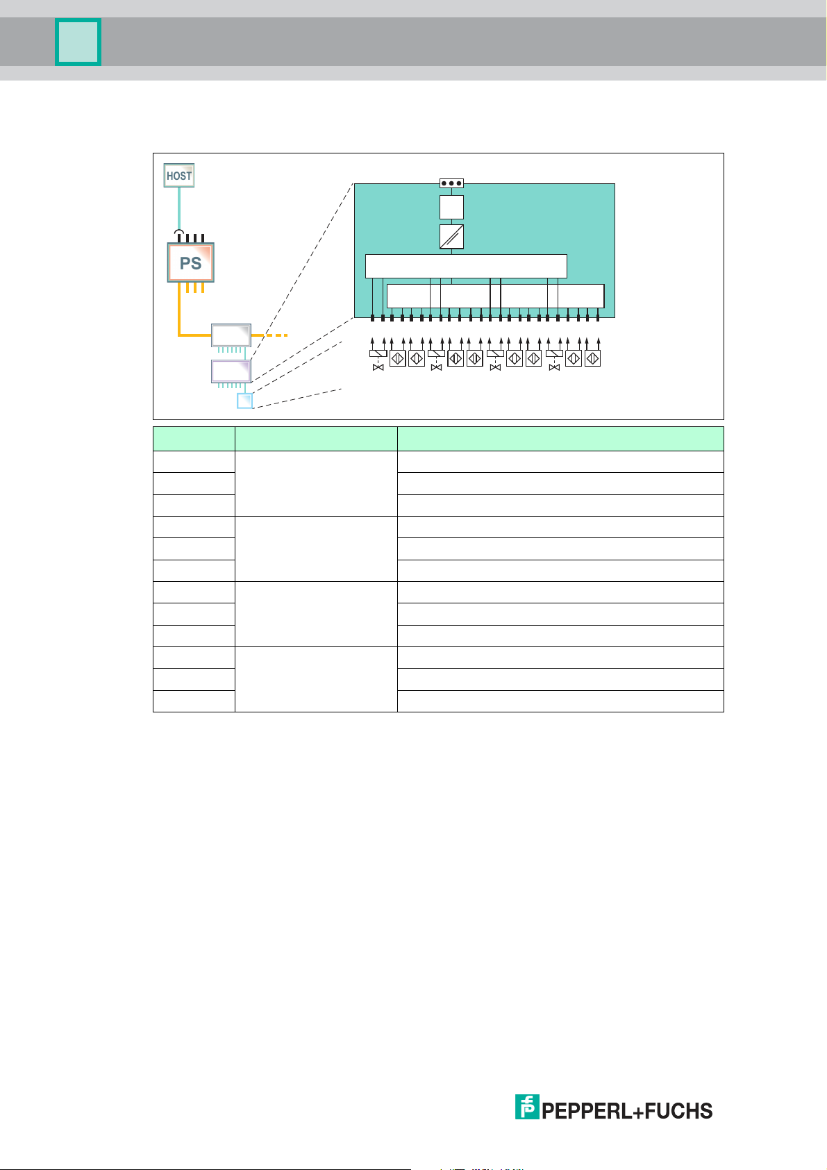
Valve Coupler Mode
In the valve coupler mode, the channels 1, 4, 7, and 10 are used to control 4 low-power valves.
The channels 2, 3, 5, 6, 8, 9, 11, and 12 are used as valve position feedback inputs for
NAMUR proximity switches or mechanical switches. Condition monitoring functions like stroke
counter, partial stroke test, and travel time survey enable you to detect evolving faults, before
they become critical for the process control.
Refer to the technical data of the MIO for specification of compatible valves and sensors. A list
of compatible low-power valves and NAMUR sensors are available on the Pepper+Fuchs
website.
FD0-VC-Ex4.PA Compatibility Mode
This mode allows the use of *D0-MIO-Ex12.PA* in an existing installation as a replacement for
FD0-VC-Ex4.PA. In order to activate this mode, use the GSD file of FD0-VC-Ex4.PA. The mode
is activated during the start-up of cyclic data exchange. Use the device type manager or device
description of the *D0-MIO-Ex12.PA* to adjust the device parameters according to the
replaced FD0-VC-Ex4.PA.
PROFIBUS Profile 3.02 Valve Coupler Compatibility Mode
PROFIBUS PA profile 3.02 defines an interoperability mode for a 4-channel valve coupler. The
corresponding GSD file is available on the PROFIBUS International website. Use the device
type manager or device description of the *D0-MIO-Ex12.PA* in order to adjust the device
parameters.
2018-07
9
Page 10
Multi-Input/Output Device
Zone 1
- +S
MAU
µC
CH1
+ - + - + - + - + - + - + - + - + -
CH4 CH7 CH10
A B A B A B A B
MUX
+
- + - + -
PI
FB/SP
Product Specifications
Modes: Valve Coupler, FD0-VC-Ex4.PA Compatibility, PA Profile 3.02 Valve Coupler
Compatibility
Channel Description Valve Coupler Mode
1 VC Channel 1,2,3 Output 1, low-power valve
2 Position feedback sensor/switch A for output 1
3 Position feedback sensor/switch B for output 1
4 VC Channel 4,5,6 Output 2, low-power valve
5 Position feedback sensor/switch A for output 2
6 Position feedback sensor/switch B for output 2
7 VC Channel 7,8,9 Output 3, low-power valve
8 Position feedback sensor/switch A for output 3
9 Position feedback sensor/switch B for output 3
10 VC Channel 10,11,12 Output 4, low-power valve
11 Position feedback sensor/switch A for output 4
12 Position feedback sensor/switch B for output 4
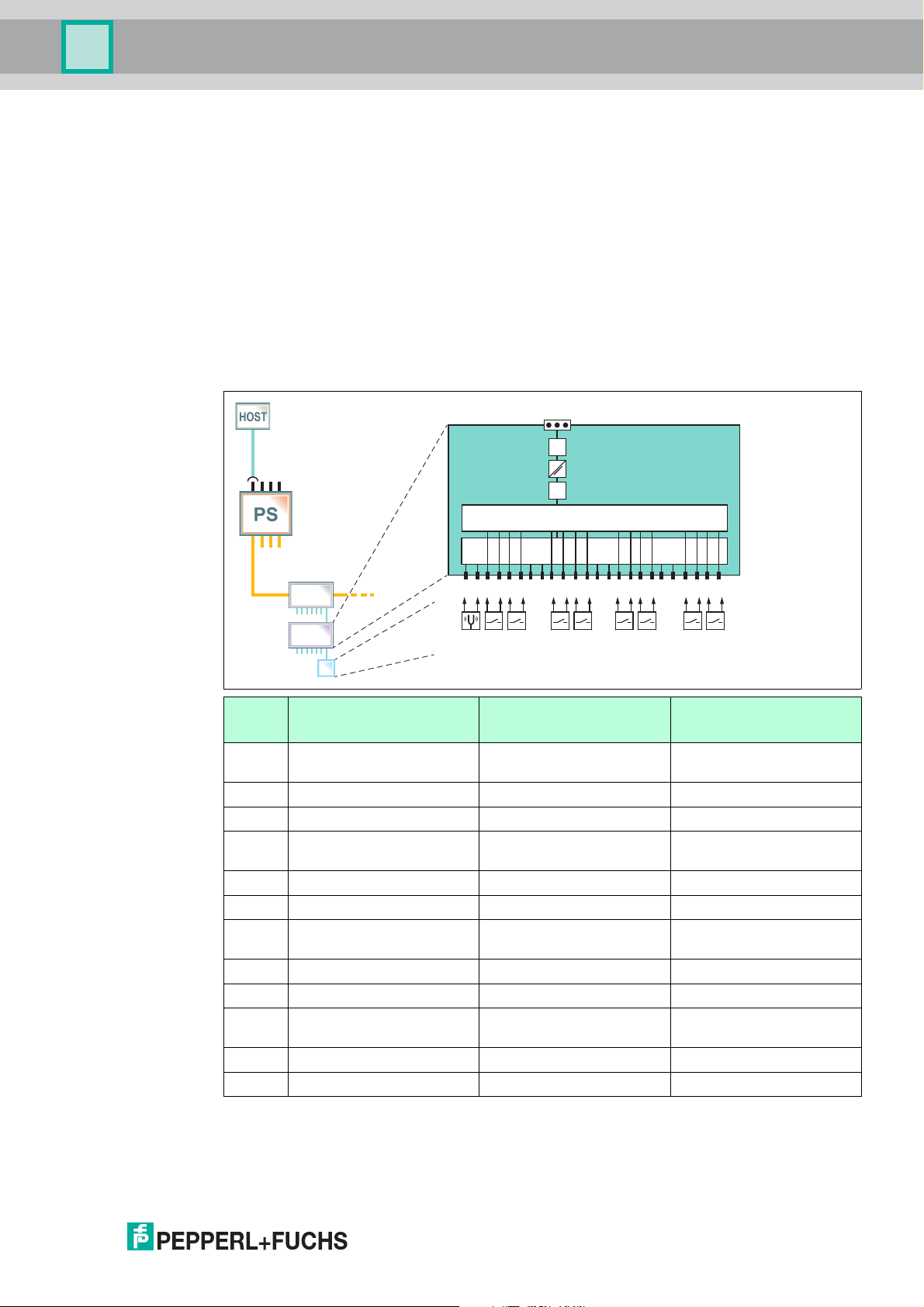
Sensor Input Mode
The device samples the inputs in 2 independent cycles. Channels 1, 4, 7, and 10 are intended
to be used for sensing multiplexed binary inputs as vibrating forks, NAMUR sensors, or
mechanical switches. Channel 1 can also be configured to be used as a frequency or counter
input. If the channel 1 frequency or counter input is activated, channels 4, 7, and 10 are
deactivated. In the device type manager, the ON-time of channel 1, 4, 7, and 10 can be
adjusted individually between 10 ms ... 10 000 ms.
10
As a parameter, the ON-time of channel 1, 4, 7, and 10 can be adjusted individually between
10 ms ... 11 000 ms.The total cycle time is the sum of the 4 individual ON-times.
Channels 2, 3, 5, 6, 8, 9, 11, and 12 are intended to be used for sensing multiplexed binary
inputs as NAMUR sensors and mechanical switches. The sampling time of 10 ms is not
adjustable. The total cycle time is calculated as follows: number of used channels * 10 ms
(minimum 50 ms). If all 8 sensors are used, the total cycle time is 80 ms.
Refer to the technical data of the MIO for the specification of compatible sensors. A list of
compatible NAMUR sensors is available on the Pepperl+Fuchs website.
2018-07
Page 11
Multi-Input/Output Device
MUX
Zone 1
-
+S
MAU
µC
MUX
CH1
+ -
+ - + - + - + -
+ -
+ - + - + - + -
+ - + -
CH4 CH7 CH10
CH2 CH3 CH5 CH6 CH8 CH9 CH11 CH12
PI
FB/SP
Product Specifications
FD0-BI-Ex12 Compatibility Mode
This mode allows the use of *D0-MIO-Ex12.PA* in an existing installation as a replacement for
FD0-BI-Ex12.PA. In order to activate this mode, use the GSD file of FD0-BI-Ex12.PA. The
configuration of the FD0.BI-Ex12.PA takes place during the start-up of the cyclic data
exchange. The device type manager allows read-only access to the configuration data. No
further adjustments are required to update an existing installation with *D0-MIO-Ex12.PA*.
PROFIBUS Profile 3.02 Sensor Input Compatibility Mode
PROFIBUS PA profile 3.02 defines an interoperability mode for a 12-channel sensor input. Use
the device type manager or device description of the *D0-MIO-Ex12.PA* in order to adjust the
device parameters.
Modes: Sensor Input, FD0-BI-Ex12.PA Compatibility, PA Profile 3.02 Sensor Input
Compatibility
Chann
el Sensor Input Modes Frequency Input Mode Counter Input Mode
1 Vibration fork or
Frequency input Counter input
sensor/switch
2 Sensor/switch Sensor/switch Sensor/switch
3 Sensor/switch Sensor/switch Sensor/switch
4 Vibration fork or
Disabled Disabled
sensor/switch
5 Sensor/switch Sensor/switch Sensor/switch
6 Sensor/switch Sensor/switch Sensor/switch
7 Vibration fork or
Disabled Disabled
sensor/switch
8 Sensor/switch Sensor/switch Sensor/switch
9 Sensor/switch Sensor/switch Sensor/switch
10 Vibration fork or
sensor/switch
11 Sensor/switch Sensor/switch Sensor/switch
Disabled Disabled
12 Sensor/switch Sensor/switch Sensor/switch
2018-07
11
Page 12

Multi-Input/Output Device
Product Specifications
2.3 Hazardous Area Installation and Use
The device may be operated in Zone 1.
For applications in Zone 1, the type of protection must be Ex i according to Entity or FISCO.
The device may be installed in Zone 2.
The type of protection for the trunk interface is Ex ec or Ex ic according to Entity or FISCO.
Independent of the type of protection of the fieldbus interface, the inputs/outputs remain
intrinsically safe and may be installed in Zone 1.
Zone 2
Danger!
Explosion hazard from live wiring of non-intrinsically safe circuits
If you connect or disconnect energized non-intrinsically safe circuits in a potentially explosive
atmosphere, sparks can ignite the surrounding atmosphere.
Only connect or disconnect energized non-intrinsically safe circuits in the absence of a
potentially explosive atmosphere.
Type of Protection "Ex i"
Danger!
Explosion hazard from wrong separation distances
Non-observance of the separation distances between circuits can result in added currents or
voltages. This can result in a current/voltage flashover generating sparks. The sparks can ignite
the surrounding potentially explosive atmosphere.
Ensure you observe the compliance of the separation distances according to
IEC/EN 60079–14.
Danger!
Explosion hazard from wrong calculation of verification of intrinsic safety
If you do not consider the maximum permissible peak values of all components when
connecting intrinsically safe devices with intrinsically safe circuits of associated apparatus, this
can lead to added currents or voltages. This, in return, can result in a current/voltage flashover
generating sparks. The sparks can ignite the surrounding potentially explosive atmosphere.
Ensure you observe IEC/EN 60079-14 and IEC/EN 60079-25 for the verification of intrinsic
safety.
Type of Protection "Ex ec"
Danger!
Explosion hazard from pollution
12
An excessively polluted surface of the device can become conductive and consequently ignite
a surrounding potentially explosive atmosphere.
Ensure that you install the device only in environments with a pollution degree 2 or better
according to IEC/EN 60664–1.
2018-07
Page 13
Multi-Input/Output Device
Zones 2, 22
Zone 0
Zones 1, 21
Non-Explosion
Hazardous
Area
Ex ic FISCO/
Ex ec
Ex i
Ex ia
FISCO
PI
*MIO-Ex12*
PI
*MIO-Ex12*
FB
Product Specifications
Danger!
Explosion hazard from exposure to potentially explosive gas atmosphere
If the device is installed in Zone 2 without mounting it in a sufficiently suitable enclosure, gas,
dust, water or other external interferences can cause the live device to spark. The sparks can
ignite the surrounding potentially explosive atmosphere.
Only mount the device in an enclosure with degree of protection IP54 according to
IEC/EN 60529. The enclosure must have an EU declaration of conformity according to the
ATEX Directive for at least equipment category 3G.
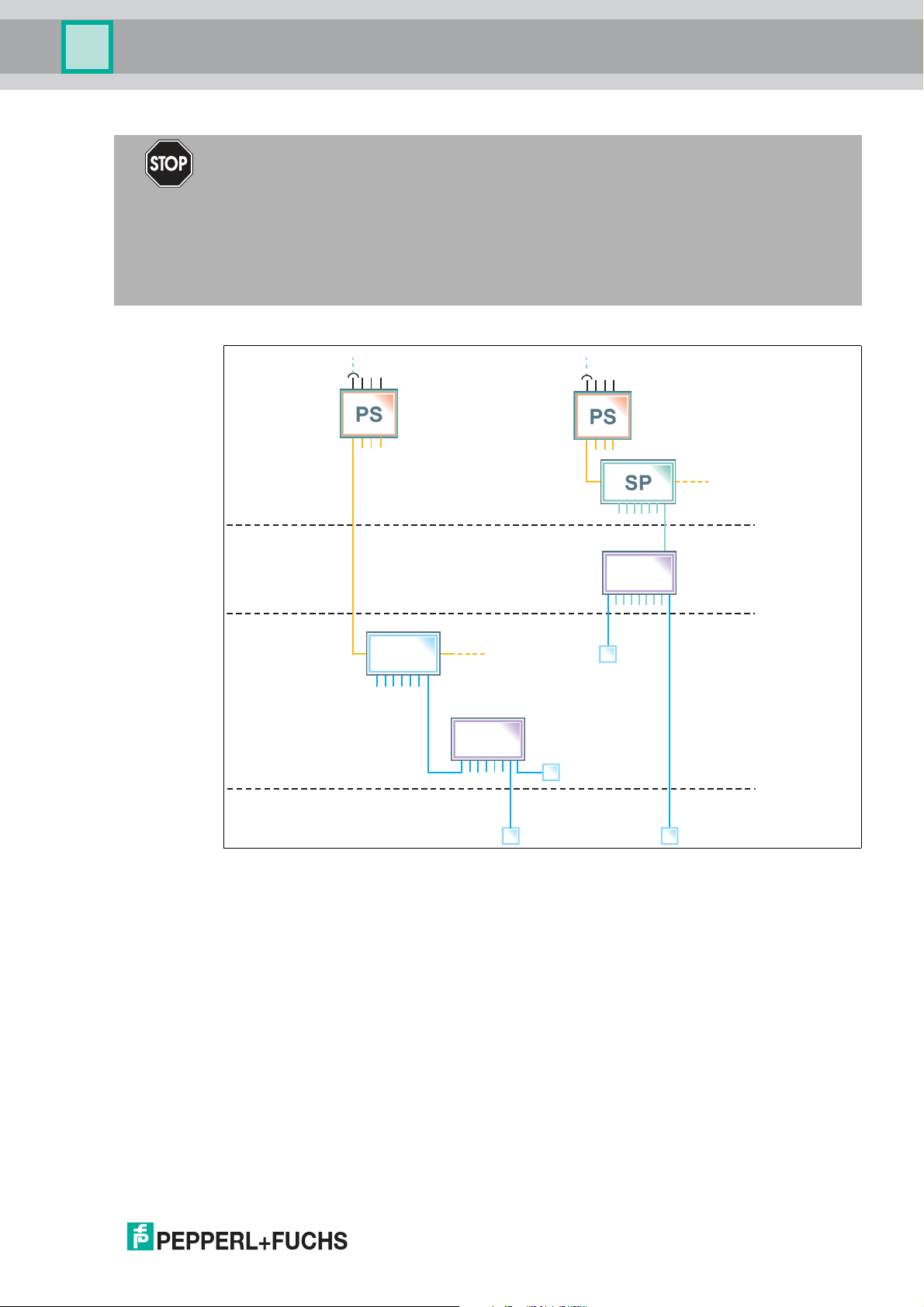
Hazardous Area Installation Options
Figure 2.1 Installation options for the multi-input/output device in the hazardous area
Observe the EC-type-examination certificate or the statement of conformity. Pay particular
attention to any "special conditions" that may be indicated.
2018-07
13
Page 14
Multi-Input/Output Device
2
3
4
1
Installation and Commissioning
3 Installation and Commissioning
In the following section you find information on how to install and commission the multiinput/output (MIO) device in your fieldbus topology.
Danger!
Danger to life from using damaged or repaired devices.
Using a defective or repaired device can compromise its function and its electrical safety.
■
Do not use a damaged or polluted device.
■
The device must not be repaired, changed or manipulated.
■
If there is a defect, always replace the device with an original device from Pepperl+Fuchs.
Danger!
Explosion hazard from damaged electronic components
Premature wear of electronic components in a device that was previously used in a general
electrical installation can cause sparks that can ignite the surrounding potentially explosive
atmosphere.
Never install devices that have already been operated in general electrical installations in
electrical installations used in combination with hazardous areas!
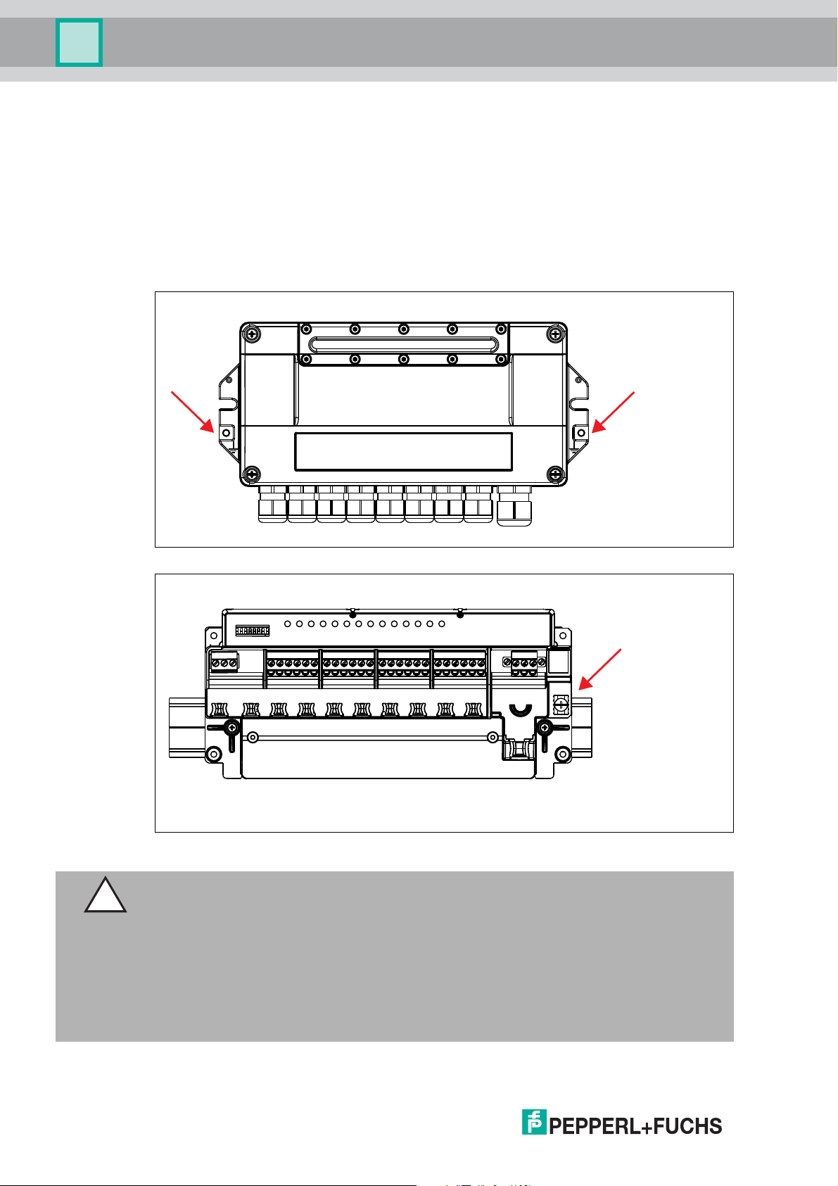
3.1 Mounting and Dismounting
Mounting/Dismounting F2D0-MIO*
F2D0-MIO* is designed for panel (wall) mounting.
■
Select mounting material that is suitable for the sub-surface (the wall).
■
Ensure that the mounting material guarantees secure fastening.
■
To attach the device: use 2 fixing screws with a diameter of 6 mm.
■
To dismount the device: Undo the fixing screws and take the device off the wall.
Mounting/Dismounting R8D0-MIO*
R8D0-MIO* is designed for mounting on a 35 mm DIN mounting rail in accordance with
EN 50022.
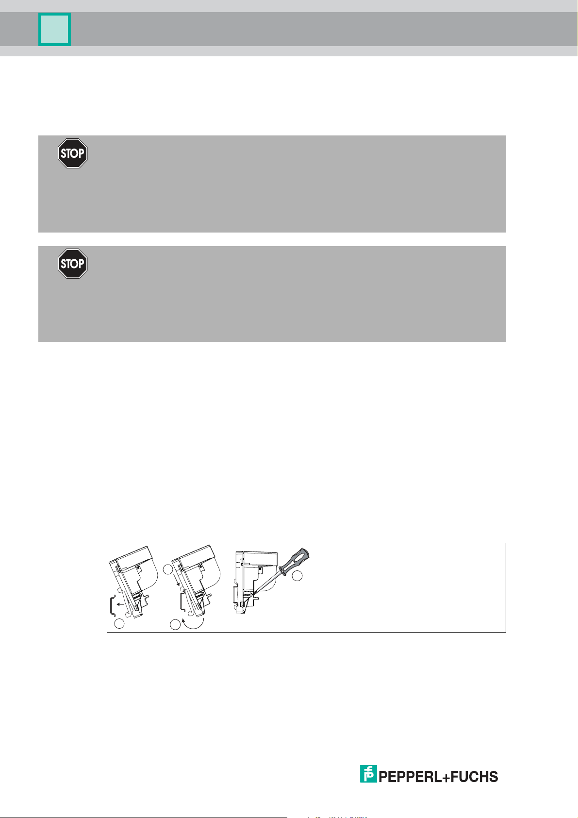
Mounting the R8D0-MIO* Electronics onto the DIN Mounting Rail
1 Place the R8D0-MIO* on the DIN mounting rail.
2 Use the top hook in order to hook the electronics onto the DIN mounting rail.
3 Move the bottom hook over the lower end of the DIN mounting rail.
4 Tighten the 2 fastening screws to attach the electronics on the DIN mounting rail.
Tightening torque: 0.4 Nm
To dismount the device: Take off the device in reverse order.
2018-07
14
Page 15

Multi-Input/Output Device
Installation and Commissioning
R8D0-MIO* Installation
Depending on the application, the R8D0-MIO* must be mounted in a suitable environment.
If mounted in Zone 2 for an Ex ec application, the environment (housing or enclosure) must
ensure the following:
■
IP54 in accordance with IEC 60529 for hazardous area Zone 2
■
Pollution degree 2 or better according to IEC/EN 60664-1
3.2 Hardware Installation
3.2.1 R8D0-MIO* Cable and Connection Information
Danger!
Explosion hazard from insufficient insulation
Insufficient dielectric strength of insulators between intrinsically safe circuits may lead to
interferences and to charge transfers that cause sparks. These sparks can ignite a potentially
explosive atmosphere.
Ensure that the dielectric strength of the insulation between intrinsically safe circuits is at least
500 V according to IEC/EN 60079–14.
Danger!
Explosion hazard or danger to life from inadequate installation of cables and connection lines
If you do not install cables and connection lines according to the instructions given in the
instruction manual, this can generate sparks that can ignite the surrounding potentially
explosive atmosphere. Furthermore, insufficient installation practice can result in electric
shock.
Ensure you carry out any cable gland installations in accordance with the instructions given in
the instruction manual.
Danger!
Explosion hazard from connection damage
Manipulating connections outside of the specified ambient temperature range can lead to
material damage, resulting in an unwanted failure of the connection. This could result in an
increased explosion hazard in potentially explosive atmospheres.
Only manipulate connections in the specified ambient temperature range.
Temperature range: -5 C° ... +70 C°
Danger!
Danger to life from incorrect installation
Incorrect installation of cables and connection lines can compromise the function and the
electrical safety of the device.
■
Observe the permissible core cross section of the conductor.
■
When using stranded conductors, crimp wire end ferrules on the conductor ends.
■
Use only one conductor per terminal.
■
When installing the conductors the insulation must reach up to the terminal.
■
Observe the tightening torque of the terminal screws.
The following section describes the different connection details of the multi-input/output with
particular reference to the torques required for a safe installation.
2018-07
15
Page 16

Multi-Input/Output Device
Installation and Commissioning
For any terminal connections, observe the following cable and connection information.
Screw Terminals: Cable and Connection Information
■
Permissible core cross section:
• Screw terminals with flexible or rigid wires: 0.2 mm2... 2.5 mm
■
Insulation stripping length: 7 mm
■
If you use stranded connectors: Crimp on wire end ferrules
■
Ensure that connectors are mechanically locked
■
Torque required for tightening terminal screws: 0.5 Nm ... 0.6 Nm
Spring Terminals: Cable and Connection Information
■
Permissible core cross section:
• Spring terminals with flexible or rigid wires: 0.5 mm2... 2.5 mm
■
Insulation stripping length: 10 mm
■
Ensure that connectors are mechanically locked
■
Torque required for tightening terminal screws: 0.5 Nm ... 0.6 Nm
2
2
Tip
Double-check that the correct torques are used when un- and reinstalling the terminal during
wiring activities!
Connecting the Trunk
The multi-input/output is connected to the trunk line via designated screw or spring terminals.
Danger!
Explosion hazard from open or missing trunk terminal cover
If the device is installed Zone 2 and powered by a non-intrinsically safe power source, carrying
out hot work on the input/output terminals with an uncovered trunk terminal can lead to contact
with solid particles or tools. This can cause the live device to spark. The sparks can ignite the
surrounding potentially explosive atmosphere.
Ensure that the trunk terminal cover is present and correctly snapped onto the connector
housing to guarantee IP30 rating.
16
2018-07
Page 17
Multi-Input/Output Device
Click!
−+ S
−+ S
+ –
+ –
+ –
Installation and Commissioning
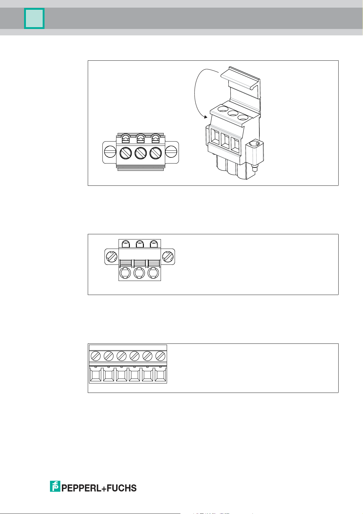
Trunk Connection with Covered Screw Terminal
+ Segment +
- Segment -
S Shield connection
Trunk Connection with Spring Terminal
+ Segment +
- Segment -
S Shield connection
Multi-Input/Output Screw Terminal
2018-07
6-pin screw terminal for multi-inputs/outputs
+ Input/output +
- Input/output -
17
Page 18
Multi-Input/Output Device
+ –
+ –
+ –
PWRCOM/
ERR
21
3
4
6
5
7
8 91011 12
ERR
CH
Configuration
ON
1 2 3 4 5 6 7 8
T G R
Extension
+ -1+ -2+ -3+ -
4
+ -
5
+ -6+ -7+ -
8
+ -
9
+ -
10
+ -
11
+ -
12
+ - S
Bus
Installation and Commissioning
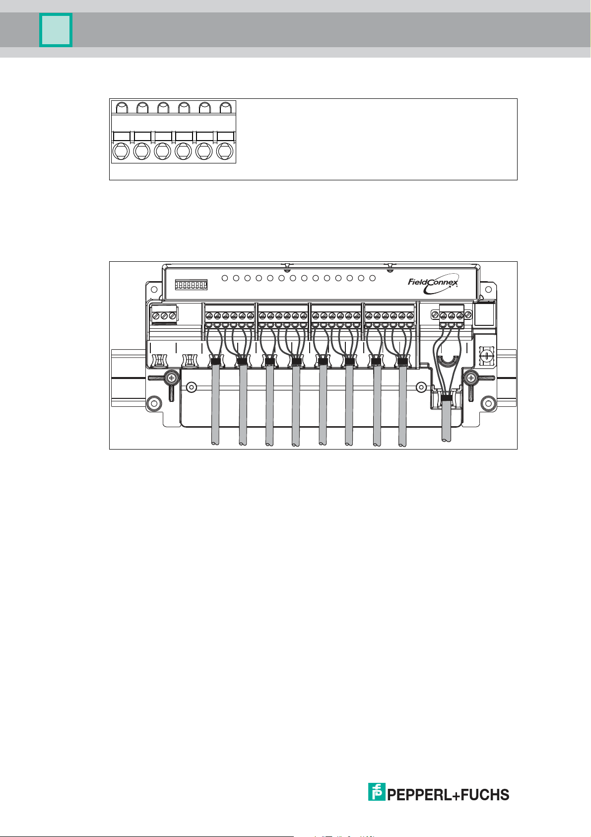
Multi-Input/Output Spring Terminal
6-pin spring terminal for multi-inputs/outputs
+ Input/output +
- Input/output -
R8D0-MIO* Sample Connection Diagram
The connection diagram shows the sample connection of the multi-input/output as a valve
coupler
Cable Position Fixture
The R8D0-MIO* electronics provides special fixtures for cable ties. To keep the cabling in a
safe position, use the fixtures with cable ties.
Cable tie width: up to 4 mm
Using Mechanical Switches
If mechanical contacts are used as valve final position feedbacks, observe the following. The
lead breakage and short circuit monitoring can be used after adding series and parallel
resistors in the lead. In this case the prerequisites are:
■
1 x 1-kOhm series resistance for monitoring short circuit
■
1 x 10-kOhm parallel resistance for lead breakage detection
18
2018-07
Page 19

Multi-Input/Output Device
Installation and Commissioning
3.2.2 F2 Housing Degree of Protection
The following section contains information concerning the installation and sealing of the cable
glands and the housing cover.
Danger!
Explosion hazard or danger to life from inadequate installation of cable glands
If you do not install cable glands according to the instructions given in the instruction manual,
this can generate sparks that can ignite the surrounding potentially explosive atmosphere.
Furthermore, insufficient installation practice can result in electric shock.
Ensure you carry out any cable gland installations in accordance with the instructions given in
the instruction manual.
Fixing the Housing Cover
Before closing the housing cover: Visually inspect the housing for any visible signs of damage
on the cover seal. If damaged, replace the seal with an original seal wear part.
Tightening torque for the screws of the housing cover: 2.5 Nm
General Information on the Installation of Cable Glands
When installing cable glands, observe the following:
■
Only insert permanently laid cables and wires into the cable glands.
• Ensure that the cables laid do not execute any strain on the cable glands.
• For permissible cable diameters, refer to the respective datasheet.
■
Use an appropriate strain relief clamp, e.g., a suitable cable clamp.
■
Seal unused cable glands with a suitable plug or replace them with appropriate screw
plugs. Observe the required degree of protection IP66.
• For a choice of stop plugs and screw plugs, refer to the respective datasheets.
• Note that the ambient temperature range can be restricted by the stopping plug.
■
Protect plastic cable glands against mechanical hazard.
■
Ensure you use the correct tightening torques when installing cable glands or plugs. For
detail see tables with torque information below.
The specific technical data may vary depending on the type of cable gland or plug you use for
your installation. The following cable glands or plug types are documented and information is
available at www.pepperl-fuchs.com:
2018-07
19
Page 20

Multi-Input/Output Device
Installation and Commissioning
Cable Entry Option Cable Gland or Plug Type
00 Sealing plug plastic:
1 x M20,
8 x M16
01 Sealing plug stainless steel:
1 x M20,
8 x M16
02 Cable glands plastic:
1 x M20,
8 x M16
03 Cable glands nickel plated brass:
1 x M20,
8 x M16
04 Cable glands stainless steel:
1 x M20,
8 x M16
05 Cable glands plastic
5 x M20 CG.PEDS.M20.PA.C.10
SP.PE.M20.PA.C
SP.PE.M16.PA.C
SP.MD.M20.SS.C
SP.MD.M16.SS.C
CG.PEDS.M20.PA.C.10
CG.PIDS.M16S.PA.C.10
CG.NA.M20S.BN.C
CG.NA.M16.BN.C
CG.NA.M20S.SS.C
CG.NA.M16.SS.C
CG.PIDS.M20.PA.C.10
SP.PE.M20.PA.C
F2D0-MIO* Input/Output Cable Glands
Sensor Entries Clamping Ranges: Torques
Cable Entry Option CG or Plug
00 1 x M20, 8 x
M16 sealing
plug plastic
01 1 x M20, 8 x
M16 sealing
plug stainless
steel
02 1 x M20, 8 x
M16 cable
glands plastic
03 1 x M20, 8 x
M16 cable
glands nickel
plated brass
04 1 x M20, 8 x
M16 cable
glands
stainless steel
05 5 x M20 cable
glands plastic
Table 3.1 The torques that are actually required depend on the clamping range. This range is
determined by the diameter of the cable and the resulting seal combinations (S1+S2+S3,
S1+S2, S1) used with the cable gland or plug. For details see the documentation on the
cable gland or plug type available at www.pepperl-fuchs.com.
Type
SP.PE.M16.PA.C- - - 1.5
SP.MD.M16.S
S.C
CG.PIDS.M16
S.PA.C.10
CG.NA.M16.B
N.C
CG.NA.M16.S
S.C
CG.PIDS.M20
.PA.C.10
S1+S2+S3 S1+S2 S1 Body
- - - 4 Nm
- 4 … 5 mm:
4 … 6 mm:
20 Nm
4 … 6 mm:
20 Nm
- 6 … 8.5 mm:
3.5 Nm
6 … 9 mm:
18 Nm
6 … 9 mm:
18 Nm
5 Nm
5 … 8 mm:
4 Nm
9 … 12 mm:
15 Nm
9 … 12 mm:
15 Nm
7 … 12 mm:
5 Nm
Nm
1.5
Nm
4 Nm
4 Nm
2 Nm
20
2018-07
Page 21

Multi-Input/Output Device
Installation and Commissioning
F2D0-MIO* Fieldbus Cable Gland
Cable Entry Option CG or Plug
00 1 x M20, 8 x
M16 blind plug
plastic
01 1 x M20, 8 x
M16 blind plug
stainless steel
02 1 x M20, 8 x
M16 cable
glands plastic
03 1 x M20, 8 x
M16 cable
glands nickel
plated brass
04 1 x M20, 8 x
M16 cable
glands
stainless steel
05 5 x M20 cable
glands plastic
05 5 x M20 cable
glands plastic
Table 3.2 The torques that are actually required depend on the clamping range. This range is
determined by the diameter of the cable and the resulting seal combinations (S1+S2+S3,
S1+S2, S1) used with the cable gland or plug. For details see the documentation on the
cable gland or plug type available at www.pepperl-fuchs.com.
Fieldbus Entries Clamping Ranges: Torques
S1+S2+S3 S1+S2 S1 Body
Type
SP.PE.M20.PA.C- - - 2 Nm
SP.MD.M20.S
S.C
CG.PEDS.M2
0.PA.C.10
CG.NA.M20S.
BN.C
CG.NA.M20S.
SS.C
CG.PEDS.M2
0.PA.C.10
- - - 5.5
Nm
- 6 … 8.5 mm:
5 Nm
4 … 6 mm:
20 Nm
4 … 6 mm:
20 Nm
6 … 9 mm:
18 Nm
6 … 9 mm:
18 Nm
- 6 … 8.5 mm:
5 Nm
7 … 12 mm:
5 Nm
9 … 12 mm:
15 Nm
9 … 12 mm:
15 Nm
7 … 12 mm:
5 Nm
2 Nm
5.5
Nm
5.5
Nm
2 Nm
SP.PE.M20.PA.CUnused thread 2 Nm
Note!
Careful when tightening cap nuts!
■
The cap nuts must be securely tightened. Tightening the cap nuts too much or not enough
both can affect the degree of protection.
■
The tightening torques of cap nuts vary, depending on the cable type used. For exact
details refer to the documentation of your cable manufacturer.
3.2.3 Grounding and Shielding
Equipotential Bonding of Devices in F2* Metal Housings
For electronic components in F2* metal housings in hazardous areas, suitable equipotential
bonding in accordance with IEC/EN 60079 is required. Therefore, the device is designed as
follows:
■
The shield (terminal S) of the intrinsically safe fieldbus trunk is internally connected to the
F2* metal housing.
■
The housing has a grounding point with a grounding screw. The grounding connection
must be secured against loosening and corrosion, e. g., by using tinned cable plates.
Note!
Ensure potential equalization of F2 Metal Housings
Ensure that the housing is connected properly to the potential equalization.
2018-07
21
Page 22
Multi-Input/Output Device
Installation and Commissioning
Shielding of the Fieldbus Trunk Using the R* Electronic Component in
Intrinsically Safe Segments
The shield (terminal S) of the fieldbus trunk is internally connected to the grounding point.
Grounding and Shielding *D0-MIO-Ex12*
Shielded cables for the valve or sensor are not required.
The device provides a grounding terminal for connecting to an equipotential bonding.
F2D0-MIO-Ex12* Grounding Points
R8D0-MIO-Ex12* Grounding Point
Connection to Equipotential Bonding System
Caution!
Risk of electric shock or property damage from inadequate grounding
If you fail to connect all metal parts of the device to protective local earth correctly, this could
result in potential equalization currents. These currents could hurt operating personnel or
cause property damage.
22
The grounding terminal is not a safety earth: Do not use the grounding terminal to ground
exposed metal parts.
Ground exposed metal parts of the device separately. Ensure that a correct grounding is
guaranteed at all times.
All shield connections are internally connected to the "Shield/Screen GND" grounding terminal.
2018-07
Page 23
Multi-Input/Output Device
1
2
3
4
2
Installation and Commissioning
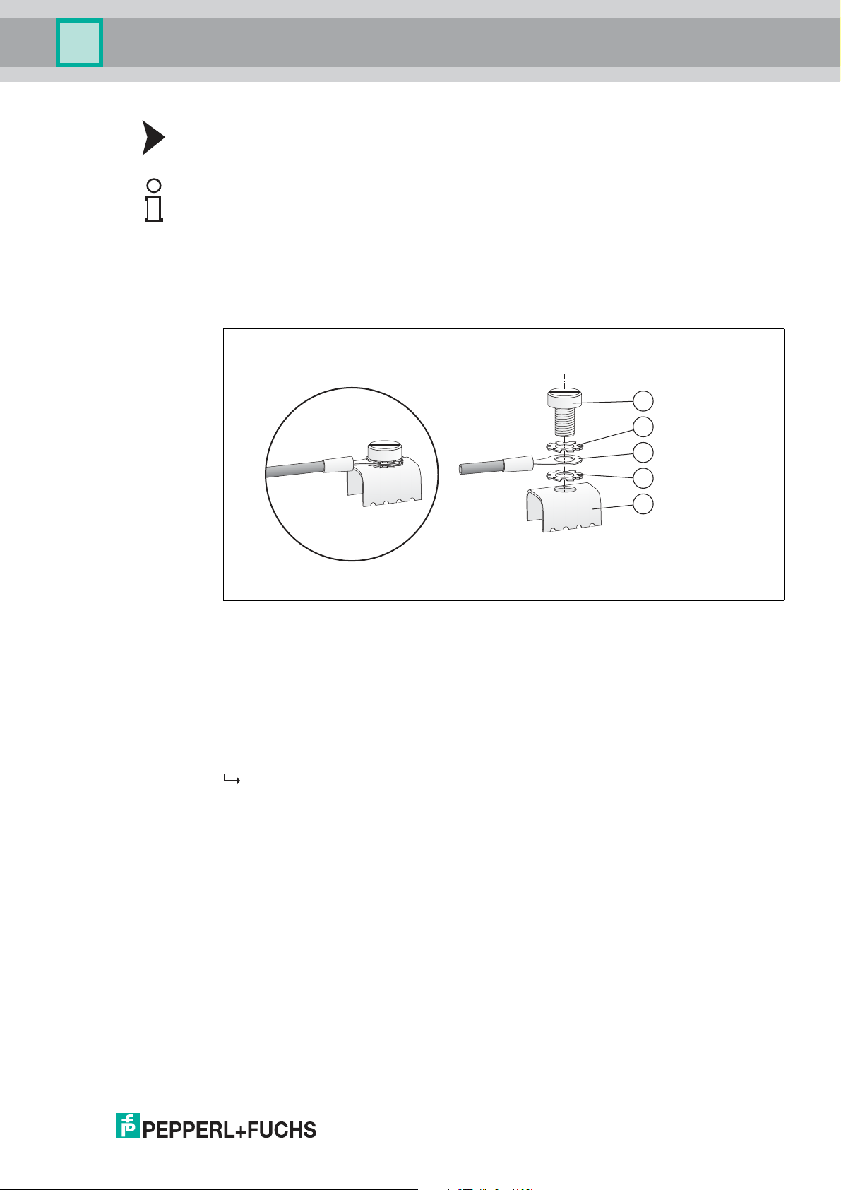
Connecting the Ground Connection Cable
Note!
Use a cable with a minimum cross section of 4 mm².
1. Connect the ground cable to a cable lug.
2. Position the cable lug over the grounding terminal with the cable pointing downwards.
3. Screw the cable lug to the grounding terminal with 2 toothed lock washers inserted between
screw, lug, and terminal as illustrated:
Figure 3.1 Connecting the ground connection cable
1 Screw
2 Toothed lock washer
3 Cable lug
4 Grounding terminal on motherboard
4. Tighten the screw with a torque of 1.5 Nm.
The cable lug is properly attached and cannot come loose.
Connect the "Shield/Screen GND" grounding terminal to an equipotential bonding system.
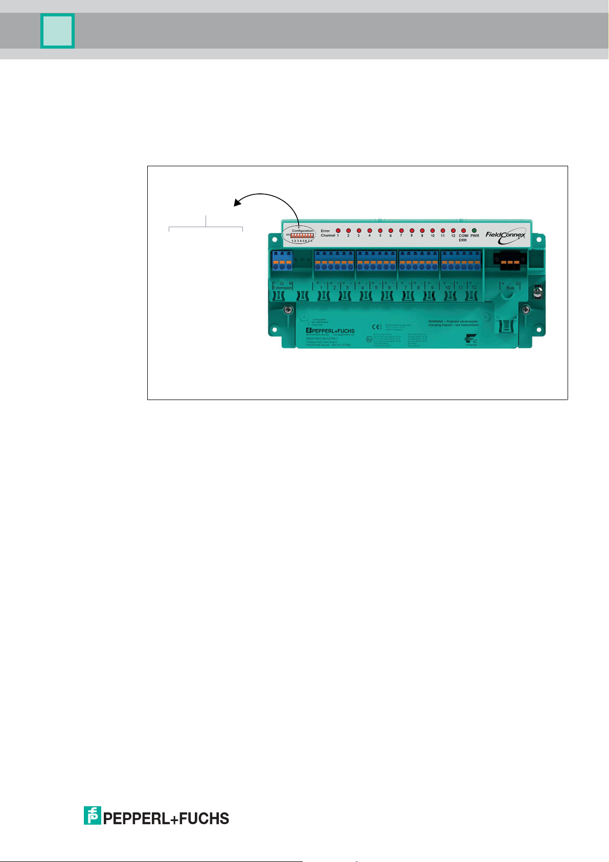
3.2.4 DIP Switch Settings
The device has 8 DIP switches:
■
DIP switches S1 ... S7: Address setting and binary coding
■
DIP switch 8: Write protection settings
Address Settings
You can assign the PROFIBUS address 0 … 125 in 2 ways. Use the hardware DIP switches of
the device or the device type manager (DTM) software.
In order to assign an address to the mulit-input/output (MIO) device in the range of 0 ... 125 as
PROFIBUS address, use the DIP switches S1 ... S7.
2018-07
23
Page 24

Multi-Input/Output Device
PROFIBUS
address setting
Position ON = logical 1
Position OFF = logical 0
1 2 3 4 5 6 7
8
Hardware
write
protection
ON
Installation and Commissioning
Any subsequent attempt to change this address via the DTM software is rejected. In this case,
the hardware DIP switch settings have priority. To change a hardware address setting again,
use the DIP switches.
After modifying the address DIP switches, the device must be rebooted in order to use the new
setting. Either disconnect the device from the fieldbus and then reconnect it, or restart the
device via the DTM.
Figure 3.2 DIP switches to set the PROFIBUS address on the device
Address S1 (20) S2 (21) S3 (22) S4 (23) S5 (24) S6 (25) S7 (26)
0 OFF OFF OFF OFF OFF OFF OFF
1 ON OFF OFF OFF OFF OFF OFF
...
126 ON ON ON ON ON ON ON
■
By default, the MIO device is delivered with the address set to 126, with the DIP switches
S1 ... S7 set to ON. This enables the modification of the address via the bus.
■
An address set via the bus remains active, even if the device has been temporarily
disconnected from the bus.
■
If an address in the range of 1 ... 125 is set via the DIP switches, this address overrules an
address previously set via the bus.
Assigning a PROFIBUS Address via the Device Type Manager
In order to enable software address setting of the MIO device, set the DIP switches either to
126 or 127. For details on how to change the address via the fieldbus, refer to the
documentation of your configuration tool.
When the address is changed, the device automatically reboots, using the new address
afterwards.
Write Protection Settings
To protect the parameters from modification you can use write protection.
Write protection has the following effects:
24
■
Acyclic write access is blocked
2018-07
Page 25
Multi-Input/Output Device
Position ON = Active
Position OFF = Not active (default setting)
PROFIBUS
address setting
1 2 3 4 5 6 7
8
OFF
ON
Hardware
write
protection
Installation and Commissioning
Activate write protection in either of the following ways:
■
Hardware write protection: Use DIP switch 8 on the device (see below).
■
Software write protection: Activate the respective parameter in the DTM software. For
more information see description of user interface no. 8, see chapter 10.2.3.
Activating Write Protection via the DIP Switch
Figure 3.3 DIP switch 8 to activate the hardware write protection
Both write protection methods work the same way, regardless of which one is activated.
3.3 PROFIBUS Ident Number Setting
For each PROFIBUS field device type of each manufacturer at least 1 unique PROFIBUS ident
number is assigned for device identification. *D0-MIO-Ex12.PA support different ident numbers
and thus, different GSD files, to configure the required mode of operation.
Depending on the required mode of operation of the device, select the ident number in the
device type manager (DTM) software. Use the PROFIBUS Ident Number parameter.
For setting the PROFIBUS ident number, see chapter 10.4 and see chapter 10.3.
Manufacturer-Specific MIO Mode Ident Number
■
Manufacturer-specific MIO mode ident number: 0x0F8B
For selecting the corresponding device mode in the DTM, see chapter 10.4 and see chapter
10.3.
FD0-VC-Ex4.PA Compatible Mode Ident Number
■
FD0-VC-Ex4.PA compatible mode ident number: 0x0841
FD0-BI-Ex12.PA Compatible Mode Ident Number
■
FD0-BI-Ex12.PA compatible mode ident number: 0x0461
PROFIBUS Profile 3.02 Valve Coupler Mode Ident Number
■
PROFIBUS profile 3.02 valve coupler mode ident number: 0x9733
PROFIBUS Profile 3.02 Sensor Input Mode Ident Number
■
PROFIBUS profile 3.02 sensor input mode ident number: 0x972B
2018-07
25
Page 26

Multi-Input/Output Device
Installation and Commissioning
Note!
Automatic Mode
By default, the device is set to "Automatic" mode: In the process of establishing cyclic
communication, the device checks if one of the supported ident numbers is set. If so, the
device automatically uses that number.
3.4 Requirements for Commissioning
Before commissioning the multi-input/output device (MIO), ensure that the following
requirements are met:
■
For acyclic communication/parameterization: A suitable FDT frame application is in place
in order to parameterize the MIO via a PROFIBUS DP master. The device type manager
(DTM) needed to run in the FDT frame application can be downloaded from Internet under
www.pepperl-fuchs.com. Refer to the release notes of the DTM for information on the
frameworks that are supported. The release notes are included in the FieldConnex® DTM
package.
■
For cyclic communication/configuration: A process control system (PCS) is prepared to
configure cyclic user data exchange via a PROFIBUS DP Master Class I.
■
The PROFIBUS master is connected to a PROFIBUS DP segment. No DP slaves need to
be available at the DP segment.
■
A PROFIBUS PA segment is connected via a Segment Coupler.
■
The bus terminations at both ends of the PROFIBUS PA segment are mounted or
switched ON.
■
A MIO device is installed at the PROFIBUS PA segment.
3.5 Parameterization and Configuration Procedure
Use the FDT frame application with the device type manager (DTM) to parameterize the
device. Parameterization is an "acyclic" communication, i. e., read/write data is read from or
stored on the device as needed. This also means that once set in the DTM, the parameters are
kept even if the device is put into operation at a later point.
Use the following checklist when commissioning the device. Skip those steps you have already
completed. For detailed information on how to proceed, refer to the chapters mentioned.
Parameterization (hardware and software):
1. Set a fixed valid PROFIBUS address 0 ... 125 via the DIP switch of the device or set the
address 126 (default setting) for assignment of the address via the configuration or parameterization tool. For more information, see chapter 3.2.4 or see chapter 10.3, and see
chapter 10.4.
2. Set the parameters for the devices in your project, e. g., PROFIBUS ident number, description parameters. For more information see chapter 3.3 and see chapter 10.3/see
chapter 10.4.
3. Set channel-related parameters. For more information, see chapter 8.
4. If needed, activate the hardware or software write protection to protect the parameters
from overwriting. For more information, see chapter 3.2.4 or description of user interface
no. 8, see chapter 10.2.3.
Configuration:
26
1. Log on to the DP master.
2. Select the GSD file to be used (manufacturer-specific, profile-specific). For more information, see chapter 3.2.
If necessary, install the respective GSD file.
2018-07
Page 27

Multi-Input/Output Device
Configuration
4 Configuration
4.1 Host System Integration
The configuration of the device in a PROFIBUS network requires a GSD file. The file describes
the details of communication capabilities and structures of cyclic data. For the *D0-MIOEx12.PA, different GSD files are available to support different modes of operation.
Mode of operation Ident number GSD file
MIO 0x0F8B PF00F8B.gsd
FD0-VC-Ex4.PA compatibility 0x0841 PF00841.gsd
FD0-BI-Ex12.PA compatibility 0x0461 PF00461.gsd
PROFIBUS profile 3.02 valve coupler 0x9733 PA09733.gsd
The manufacturer-specific GSD files for MIO mode of operation offer the full functionality of the
devices. The GSD file is available on the Internet under www.pepperl-fuchs.com.
The profile-specific GSD files are defined by the PROFIBUS PA profile 3.02. The GSD files
offer a limited, standardized functionality that guarantees interoperability between devices of
different manufacturers. Profile-specific GSD files are available on the Internet under
www.pepperl-fuchs.com.
The FD0-VC-Ex4.PA and FD0-BI-Ex12.PA GSD files are used if in an existing installation of a
device has to be replaced. The GSD files of preceeding Pepperl+Fuchs process interfaces are
available on the Internet under www.pepperl-fuchs.com.
4.2 Configuration of Cyclic Communication
Prerequisite: The GSD file is installed in your process system. For more information, see
chapter 4.1.
During cyclic data exchange, "user data" is exchanged in regular intervals between the master
and the slave or bus, e. g., between a process control system and a field device. User data
includes, e. g., measurement values, limit position feedback, and output data, etc. The bus
cycle time depends on the number of nodes and the amount of data that is transmitted.
The cyclic data is represented in so called “modules” which are mapped to slots. For each
hardware channel a module can be selected. The module data consists of a combination of
input and output data of different variables. Modules of the different operation modes are not
allowed to be mixed other than stated below. The supported types of modules are described in
the specific GSD files.
Module types for the valve coupler mode and the FD0-VC-Ex4.PA compatibility mode In the
valve coupler mode the following variables for cyclic communication are available:
■
Empty module: Used if a channel is not used for cyclic communication.
■
OUT_D: Input value and status of position feedback monitor.
■
SP_D: Specified setpoint value of valve position in the "Auto" mode.
■
RB_D: Feedback of valve position and the states of the position feedback inputs and their
line fault condition.
■
CB_D: Detailed status, alarm, and fault condition of the valve.
■
RIN_D: Specified setpoint value of host in the "RCas" mode of operation.
■
ROUT_D: Setpoint value feedback to host in the "RCas"mode of operation.
2018-07
27
Page 28

Multi-Input/Output Device
Configuration
Modules (combination of
variables) Description Byte length
EMPTY_MODULE Empty module. Used if a channel
OUT_D Input value and status of sensor
SP_D Setpoint value of the valve 2 0
SP_D+RB_D Setpoint value + position feedback 2 2
SP_D+CB_D Setpoint value + diagnostics 2 3
SP_D+RB_D+CB_D Setpoint value + position feedback
RIN_D+ROUT_D Setpoint value host 2 2
RIN_D+ROUT_D+CB_D Setpoint value host + diagnostics 2 5
SP_D+RB_D+RIN_D+ROUT_D+
CB_D
is not used.
input
+ diagnostics
Setpoint value host + final position
feedback (PFC) + diagnostics
Input Output
0 0
2 0
2 5
4 7
In the valve coupler mode, up to 12 modules per *D0-MIO-Ex12.PA are supported.
Module types for the sensor input mode and FD0-BI-Ex12.PA compatibility mode In the sensor
input mode, the following variables for cyclic communication are available:
■
Empty module: Used if a channel is not used for cyclic communication.
■
OUT_D: Value of the sensor input and the corresponding status information.
■
OUT: Value for frequency input with the corresponding status. Not applicable to the FD0BI-Ex12.PA compatibility mode.
■
OUT long: Value for frequency input with the corresponding status. Module description in
long format. Not applicable to the FD0-BI-Ex12.PA compatibility mode.
■
OUT short: Value for frequency input with the corresponding status. Module description in
short format. Not applicable to the FD0-BI-Ex12.PA compatibility mode.
■
OUT_C: Value for counter input with corresponding status. Not applicable to the FD0-BIEx2.PA compatibility mode.
■
OUT_C_RESET: 1 output byte used to reset the sensor input and the corresponding
status information.
28
2018-07
Page 29

Multi-Input/Output Device
Configuration
Modules (combination of
variables) Description Byte length
EMPTY_MODULE Empty module. Used if a channel
OUT_D Input value and status of the input
OUT Input value and status of the input
OUT long OUT long: Value for frequency
OUT short OUT short: Value for frequency
OUT_C Input value and status of the input
OUT_C + OUT_C_RESET Counter input value and
Input Output
0 0
is not used.
2 0
if binary sensors are used.
5 0
if configured in frequency mode.
Not applicable to the
FD0–BI–Ex12.PA compatibility
mode.
5 0
input with the corresponding
status. Module description in long
format. Not applicable to the FD0BI-Ex12.PA compatibility mode.
5 0
input with the corresponding
status. Module description in short
format. Not applicable to the FD0BI-Ex12.PA compatibility mode.
5 0
if configured in counter mode. Not
applicable to the FD0–BI–Ex12.PA
compatibility mode.
5 1
corresponding status in
combination with counter reset
value.
4.3 Cyclic Communication Data Description
The following sections describe the device variables involved in cyclic communication. Most of
these variables contain a data part and a status byte. The status supports 2 different sets of
coding: the classic status and the condensed status. The condensed status offers gradual
prioritized information which is the most suitable to support you with process control and
maintenance tasks. Whereas the classic status follows a fixed mapping between failure cause
and status message, the condensed status can be configured depending on available failure
causes. For more information, refer to the device type manager description on diagnostic and
status mapping.
4.3.1 Valve Coupler Mode and FD0-VC Compatibility Mode Variables
The following section offers information on the following valve coupler mode variables:
■
SP_D
■
RIN_D
■
RB_D
■
ROUT_D
■
CB_D
■
OUT_D
2018-07
29
Page 30

Multi-Input/Output Device
Configuration
SP_D
The status of SP_D influences the control of the valve. The SP_D variable consists of 2 bytes:
1. The first byte represents the setpoint value of the valve for the “auto” mode of operation of
the function block.
2. The second byte represents the status.
Value Description
0 Set position “closed”
1 ... 255 Set position “open”
Classic Status Value Mnemonic Description
0xA0 GOOD (NC)-IFS (Initiate fail-safe.)
0x80 GOOD (NC)-OK Valid setpoint value.
>= 0x40 UNCERTAIN
GOOD (C)
GOOD (NC)
<= 0x3F BAD All values 00 h ... 3 Fh.
Command for control to change to the
fail–safe state.
Recommended to be used as the default
value for "GOOD".
Valid setpoint valueAll values 40h ... BFh
except A0h.
Value 80h recommended to be used
preferably.
The setpoint value is only valid if the value of the status byte (second byte) is "GOOD" (NC)OK" (80h).
Note!
Controlling the Valve
The setpoint value is not the control value of the valve. Which value opens or closes a valve,
depends on the setting of the "invert setpoint" parameter. For more information, see chapter
8.1.
Example!
Setting the Invert Setpoint Parameter
If the Invert Setpoint parameter is set to "OFF", the setpoint value is not inverted. The setpoint
value "0" controls the valve in the "closed" position. Any other setpoint value from 1 ... 255
controls the valve in the "open" position.
If the Invert Setpoint parameter is set to "ON", the coding of the setpoint value is inverted. That
means, the setpoint value "0" controls the valve in the "open" position. Any other setpoint value
from 1 ... 255 controls the valve in the "closed" position.
30
2018-07
Page 31

Multi-Input/Output Device
Configuration
RIN_D
The variable RIN_D contains the specified setpoint value of the valve position in the "RCas"
mode. Coding is identical to SP_D.
The relevant status values are:
Classic Status Value Mnemonic Description
0xC0 GOOD (C)-OK Valid setpoint value.
0xC1 GOOD (C)-IA (Initialization acknowledgment.)
0xE0 GOOD (C)-IFS (Initiate fail-safe.)
< 0xC0 GOOD (NC)
UNCERTAIN
BAD
Clearance from control system to change to
the RCas mode.
Command for channel to change to the Auto
mode.
Invalid setpoint value.
Change to Auto mode.
Example!
Setting the Valve Position
If the variable RIN_D is 0 with the Invert Setpoint" parameter set to "OFF", the setpoint value is
not inverted. The setpoint value "0" controls the valve in the "closed" position. Any other
setpoint value from 1 ... 255 controls the valve in the "open" position.
If RIN_D is 0 with the Invert Setpoint parameter set to "ON", the coding of the setpoint value is
inverted. The setpoint value "0" controls the valve in the "open" position. Any other setpoint
value from 1 ... 255 controls the valve in the "closed" position.
RB_D
The variable RB_D gives the feedback of the valve position, the states of the position inputs,
and their lead faults. The variable consists of 2 bytes: the first byte represents the readback and
the second byte represents the status.
The coding of the readback is as follows:
Bit Description
0+1 Valve position 0 = unknown, 1 = closed, 2 = open, 3 = intermediate
2 Position feedback A 0 = actuated, 1 = not actuated
3 0 = no lead short circuit, 1 = lead short circuit
4 0 = no lead breakage, 1 = lead breakage
5 Position feedback B 0 = actuated, 1 = not actuated
6 0 = no lead short circuit, 1 = lead short circuit
7 0 = no lead breakage, 1 = lead breakage
position
2018-07
31
Page 32

Multi-Input/Output Device
Configuration
The coding of the status is as follows:
Classic Status Value Mnemonic Description
0x80 GOOD (NC)-OK Feedback value valid.
0x84 GOOD (NC)-UE (Update event.)
0x0C BAD (NC)-DF (Device failure.)
0x10 BAD (NC)-SF Position feedback sensor combination not
0x11 BAD (NC)-SF Lead short circuit
0x12 BAD (NC)-SF Lead breakage
ROUT_D
The variable ROUT_D consists of 2 bytes providing the setpoint value of the valve which is retransferred by RIN_D for monitoring and the status. This setpoint value does not include
information of the states of the position feedback sensors. The status is mainly used to control
the sequence of module change in case of failure.
10-s message for parameter changes.
Electric hardware fault. Send the device to
Pepperl+Fuchs for repair.
allowed.
The coding of the status is as follows:
Classic Status Value Mnemonic Description
0xC0 GOOD (C)-OK Valid setpoint value.
0xC2 GOOD (C)-IR (Initialization request.)
0xCC GOOD (C)-NI (Not invited.)
0x0C BAD-DF (Device failure.)
0x1C BAD-OS (Out of service.)
Clearance request from slave to master in
order to change to the RCas mode.
RCas is not set as the target mode.
Electric hardware fault. Send device to
Pepperl+Fuchs for repair.
Is set in the OoS mode.
32
2018-07
Page 33

Multi-Input/Output Device
Configuration
CB_D
The variable CB_D provides detailed status, alarm, and fault signals of the valve. The variable
consists of 3 bytes.
The information is bit-coded as follows:
Bit Description
0 The valve is set to fail-safe state.
1 Unused
2 Unused
3 Unused
4 After a correct switching operation, the valve has left the appropriate end
5 Lead breakage of the valve.
6 Lead short circuit of the valve.
7 Unused
8 Valve is in the process of opening.
9 Valve is in the process of closing.
10 Update event. 10-s message while changing the parameters of this
11 The channel is in simulation mode.
12 Unused
13 Unused
14 Valve moved into the mechanical safety position.
position or the PFCs show an invalid position.
channel.
■
In case of fault if fault states = Actuator Fail Action.
■
In Manual mode if status of manual setpoint of valve is BAD.
15 A cyclic functional test is currently carried out.
16 The limit value for the stroke counter has been exceeded.
17 The breakaway time OPEN-CLOSED including tolerance has been
18 The breakaway time CLOSED-OPEN including tolerance has been
19 A fault occurred during the cyclic function test of the valve.
20 The transit time OPEN-CLOSED including tolerance has been
21 The transit time CLOSED-OPEN including tolerance has been
22 Actuating drive or valve mechanically blocked.
23 Unused
exceeded/fallen below.
exceeded/fallen below.
exceeded/fallen below.
exceeded/fallen below.
2018-07
33
Page 34

Multi-Input/Output Device
Configuration
OUT_D
The variable OUT_D consists of 2 bytes. The first byte contains the process value of the
sensor, the second byte contains the status of the data.
The structure of the first byte, i. e., the process value of the sensor input, is as follows:
Bit 0 Value of the sensor input 0: low current
Bit 1 … 7 na Not used
The structure of the second byte, containing the status of the data, is as follows:
Classic Status Value Mnemonic Description
0x80 GOOD-OK No error, the input value is valid.
0x12 BAD-SF (Sensor failure.)
0x11 BAD-SF (Sensor failure.)
0x0C BAD-DF (Device failure.)
0x1C BAD-OS (Out of specification.)
1: high current
Lead breakage.
Lead short circuit.
Hardware fault.
No valid value of the sensor has been read
(after power-up of the device).
The values of the position feedback sensors in the MIO valve coupler mode can be transmitted
individually to calculate e. g. the position of a valve in the process control system.
4.3.2 Sensor Input Mode and FD0-BI Compatibility Mode Variables
The following section offers information on the following sensor input mode variables:
■
Discrete Input Variables
■
Frequency and Counter Variables
Discrete Input Variables
The variable OUT_D consists of 2 bytes. The first byte contains the process value of the
sensor, the second byte contains the status of the data.
The structure of the first byte, i. e., the process value of the sensor input, is as follows:
Bit 0 Value of the sensor input 0: low current
Bit 1 … 7 na Not used
1: high current
34
2018-07
Page 35

Multi-Input/Output Device
Configuration
The structure of the second byte, containing the status of the data, is as follows:
Classic Status Value Mnemonic Description
0x80 GOOD-OK No error, the input value is valid.
0x12 BAD-SF (Sensor failure.)
0x11 BAD-SF (Sensor failure.)
0x0C BAD-DF (Device failure.)
0x1C BAD-OS (Out of specification.)
Frequency Input Variables
The OUT variable consists of 5 bytes. The first 4 bytes contain the process value of the
frequency or counter. The 5th byte contains the status of the process value.
Lead breakage.
Lead short circuit.
Hardware fault.
No valid value of the sensor has been read
(after power-up of the device).
The OUT long variable represents the value for the frequency input with the corresponding
status. Module description in long format. Not applicable to the FD0-BI-Ex12.PA compatibility
mode.
The OUT short variable represents the value for the frequency input with the corresponding
status. Module description in short format. Not applicable to the FD0-BI-Ex12.PA compatibility
mode.
For the frequency input, the sensor value is formatted in float format according to IEEE 754.
The structure of the 5th byte, containing the input status, is as follows:
Classic Status Value Mnemonic Description
0x80 GOOD-OK No error, the input value is valid.
0x12 BAD-SF (Sensor failure.)
Lead breakage.
0x11 BAD-SF (Sensor failure.)
Lead short circuit.
0x0C BAD-DF (Device failure.)
0x1C BAD-OS (Out of specification.)
Hardware fault.
No valid value of the sensor has been read
(after power-up of the device).
2018-07
35
Page 36

Multi-Input/Output Device
Configuration
Counter Input Variables
The OUT_C variable consists of 5 bytes. The first 4 bytes contain the process value of the
frequency or counter. The 5th byte contains the status of the process value.
For the counter input the sensor value is formatted in unsigned 32.
The structure of the 5th byte, containing the input status, is as follows:
Classic Status Value Mnemonic Description
0x80 GOOD-OK No error, the input value is valid.
0x12 BAD-SF (Sensor failure.)
0x0C BAD-DF (Device failure.)
0x1C BAD-OS (Out of specification.)
Counter Output Variable OUT_C_RESET
Lead breakage.
Hardware fault.
No valid value of the sensor has been read
(after power-up of the device).
The variable OUT_C_RESET contains the reset value in counter mode.
■
= 0: Counter is in normal operation.
■
> 0: Counter is in reset mode. As long as the counter is in reset mode, the following
applies:
• OUT_C variable = 0
• OUT_C.status = 0x4F (uncertain-initial value-const.)
4.4 Cyclic Communication Data Structure
In the following section explains the order of the module data transmitted in the cyclic data
exchange.
4.4.1 Valve Coupler Mode and FD0-VC-Ex4.PA Compatibility Mode
The length of the module data depends on the module type. For more information, see chapter
4.2.
Byte 1 ... n
Module
data+status
CH 1/ output 1
If an “empty” module is used instead of a module containing data, no data is transferred during
the data exchange for the corresponding channel.
Module
data+status
CH 4/ output 2
Module
data+status
CH 7/ output 3
Module data+status CH 10/ output 4
36
Note!
Discrete Input Modules
Discrete input (DI) modules are supported in the MIO mode for valve couplers only. These are
the OUT_D variables of the position feedback sensors. These variables work as described in
the section "Discrete Input Variables", see chapter 4.3.2.
2018-07
Page 37

Multi-Input/Output Device
Configuration
4.4.2 Example of a Typical Configuration in Valve Coupler Mode
Out of 4 available valves, valve 2 and valve 3 are assigned.
Lead monitoring is activated both valves: CB_D
For the valve 3, an additional final position feedback and monitoring is required: RB_D
The mode of operation for valve 2 is Auto and for valve 3 it is RCas.
In this setup, the list of the modules used should have the following structure:
Pos. Module Use
1 EMPTY_MODULE Valve 1: Empty module as the valve is
2 SP_D+CB_D Valve 2: Specified setpoint value of
3 SP_D+RB_D+RIN_D+ROUT_D+CB_D Valve 3: Specified setpoint value of
4 EMPTY_MODULE or no specification Valve 4: Empty module or no
not used
valve with fault feedback in Auto mode.
valve with fault feedback and final
position monitoring (likewise with fault
feedback) in RCas mode. The identifier
must contain the RB_D variable for the
final position feedback.
assignment as the valve is not used
and no used channels follow.
The length of the user data transferred to the device (output data) is: 0 + 2 + 4 + 0 = 6 bytes
The length of the user data transferred from the device (input data) is: 0 + 3 + 7 + 0 = 10 bytes
4.4.3 Sensor Input Mode and FD0-BI-Ex12.PA Compatibility Mode
Example: Binary sensor input only, channels 1 … 12:
■
Channels 1, 4, 7, 10: sensor measurement group 1
■
Channels 2, 3, 5, 6, 8, 9, 11, 12: sensor measurement group 2
Byte 1 2 3 4 5 6 7 8 9 10 11 12 ... 23 24
Content
Data CH1
Status CH1
Data CH4
Status CH4
Data CH7
Status CH7
Data CH10
Status CH10
Data CH2
Status CH2
Data CH3
Status CH3
Example:
Combined frequency or counter and sensor input:
■
Channel 1: frequency or counter input
■
Channels 2, 3, 5, 6, 8, 9, 11: sensor inputs
Note: Channels 4, 7, and 10 are empty modules and cannot receive data.
Byte 1 ... 4 5 6 7 8 9 10 ... 18
...
Data CH12
Status CH12
Content
If an “empty” module is used instead of a module containing data, no data is transferred during
2018-07
the data exchange for the corresponding channel.
Data CH1
Status CH1
Data CH2
Status CH2
Data CH3
Status CH3
Data CH5
...
Status CH11
37
Page 38

Multi-Input/Output Device
Configuration
4.4.4 Example of a Typical Configuration in Sensor Input Mode
Out of 4 available vibrating forks, fork 1 and fork 3 are used.
Out of the 8 available sensors, sensor 2 and sensor 3 are used.
Settling time of the vibrating forks that is set: 4 s.
In this setup, the list of the modules used should have the following structure:
Pos. Module Use
1 OUT_D Vibrating fork 1
2 EMPTY_MODULE Vibrating fork 2 is not used
3 OUT_D Vibrating fork 3
4 EMPTY_MODULE Vibrating fork 4 is not used
5 EMPTY_MODULE Sensor 1 is not used
6 OUT_D Sensor 2
7 OUT_D Sensor 3
8 ... 12 EMPTY_MODULE Sensor 4 ... 8 is not used
A typical parameterization string is, e. g.: 00 00 00 53 01 02 01 03 02 01
Explanation
00 00 00 53 01 02 03 03 02 01
3 bytes =
always "0"
At maximum, 5 more bytes could follow for the sensors 4 ... 8.
During the cyclic user data exchange, the following 8 bytes are transferred:
1. Byte 2. Byte 3. Byte 4. Byte 5. Byte 6. Byte 7. Byte 8. Byte
Data
Fork1
Configuration byte
for fork 1,
Status
Fork1
incl. settling
time setting
Fork 2,
deactivated
Data
Fork3
Fork 3,
deactivated
Status
Fork3
Fork 4,
deactivated
Data
Sens2
Sensor 1,
deactivated
Status
Sens2
Sensor 2
Data
Sens3
Sensor 3
Status
Sens3
38
2018-07
Page 39

Multi-Input/Output Device
Parameterization in Cyclic Communication (Set_Prm)
5 Parameterization in Cyclic Communication (Set_Prm)
5.1 Condensed Status and Diagnosis
The device supports the classic and condensed status and diagnostic messages. For more
information, see chapter 6.3. During parameterization it is possible to switch between the
modes. The PRM_COND parameter defines whether the condensed status and diagnostic
status are enabled or disabled.
Note!
Compatibility Modes
The FD0-VC-Ex4.PA and FD0-BI-Ex12 compatibility modes only support the classic status!
5.2 FD0-BI-Ex12 Compatibility Mode
In the FD0-BI-Ex12 compatibility mode, the device can be configured by using the PRM_DATA
PROFIBUS parameterization string. For each of the 12 sensor inputs/modules 1 byte is
transmitted. The first byte contains the lead breakage and lead short circuit option and the
settling time for CH1, CH4, CH7, and CH10. The following bytes contain the lead breakage and
lead short circuit option for the CH2 … CH12.
Content of the first parameterization byte:
Bit 7 Bit 6 Bit 5 Bit 4 Bit 3 Bit 2 Bit 1 Bit 0
Settling for the sensor inputs of the hardware
channels, 1, 4, 7, and 10
Coding of the lead breakage/lead short circuit settings (bit 0 … 4):
0: Lead breakage + short circuit check (LB and SC checks are activated)
1: Lead breakage check (LB check is activated)
2: Short circuit check (SC check is activated)
3: No check (LB is deactivated)
Coding of the settling time settings (bit 5 … 7):
0: 1 s (default)
1: 250 ms
2: 500 ms
3: 2 s
4: 3 s
5: 4 s
Lead breakage, lead short circuit settings
6: 5 s
2018-07
39
Page 40

Multi-Input/Output Device
Parameterization in Cyclic Communication (Set_Prm)
The parameterization bytes 2 … 12 have the following content:
Bit 7 Bit 6 Bit 5 Bit 4 Bit 3 Bit 2 Bit 1 Bit 0
Not used Lead breakage, lead short circuit settings
Coding of the lead breakage/lead short circuit settings (low nibble):
0: Lead breakage + short circuit check (LB and SC checks are activated)
1: Lead breakage check (LB check is activated)
2: Short circuit check (SC check is activated)
3: No check (LB check is deactivated)
For sensors that are configured as empty modules, the lead breakage and lead short circuit
checks are deactivated independently of the content of their parameterization byte.
40
2018-07
Page 41
Multi-Input/Output Device
PWRCOM/
ERR
21
3
4
6
5
7
8 9
10
11 12
ERR
CH
®
1 2 3
Troubleshooting and Diagnosis
6 Troubleshooting and Diagnosis
The following information helps you to identify problems with the multi-input/output device and
interpret diagnostic issues.
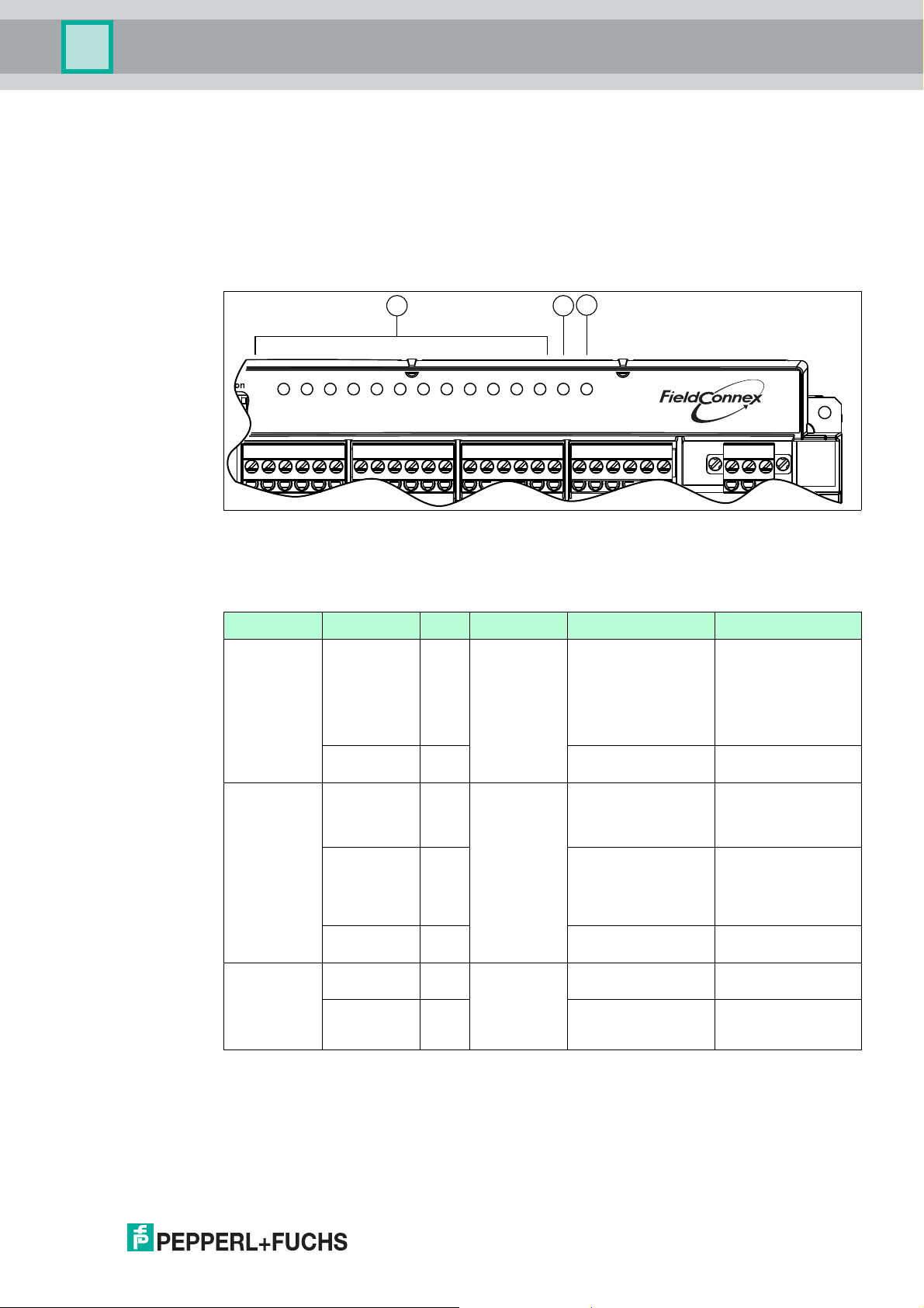
6.1 LED Status and Error Indication
The device is providing LED indication for each channel, the communication status and the
fieldbus voltage.
1 LED CH ERR 1 ... 12 for indicating channel errors
2 LED COM ERR for indicating communication errors
3 LED PWR for indicating operation
LED Indication Color Information Reason Remedy
CH ERR Flashing Red Status of the
corresponding
channel
OFF -- Channel works as
COM ERR ON Red Communicatio
n status.
Flashing Red No communication
OFF -- Cyclic communication
PWR ON Green Status of the
fieldbus
OFF -- No fieldbus voltage at
power.
Lead breakage or
Check the cable wires.
short circuit of valve or
sensor connection.
Only available if wire
check is activated and
mode of operation is
not "out of service".
--
expected.
Hardware error. Hardware error in the
device. Check the
device and replace if
required.
Device is not
activity.
configured for cyclic
communication.
Check the PROFIBUS
master.
--
with master, class I.
Fieldbus voltage at the
--
trunk.
Check the fieldbus
the trunk.
power supply.
Check the trunk cable.
2018-07
41
Page 42

Multi-Input/Output Device
Troubleshooting and Diagnosis
6.2 Device Internal Errors
The device detects internal error conditions that impact the following aspects:
■
Status information of cyclic data: For more information: configuration of cyclic
communication see chapter 4.2, cyclic communication data structure see chapter 4.4,
initialization run (valve coupler) see chapter 6.4.
■
Diagnostic content. For more information, see chapter 6.3.
■
COM ERR LEDs: For more information, see chapter 6.1.
Error Description Impact on
Hardware IO
Hardware memory
■
Internal communication
between fieldbus board
and IO board failed
■
Hardware error on
IO board
■
Nonvolatile memory
verification failed
■
Nonvolatile memory write
access failed
Condensed status:
■
Hardware error
Classic diagnosis:
■
Hardware error
Field diagnostics:
■
Device failure
LEDs:
■
COM ERR LED: ON
Classic diagnosis:
■
Memory error
Field diagnostics:
■
Device failure
6.3 Diagnosis
The PROFIBUS PA profile defines 2 different diagnostic modes supported by the device:
■
Classic diagnosis
■
Condensed diagnosis
The condensed diagnosis gives more structured and focused information of the device tailored
for the use in process systems and maintenance stations. You can adapt failure causes that
change the diagnostic state according to your needs. For more information, refer to the device
type manager (DTM).
Bytes 1 … 10 of the diagnostic extension and the diagnostic structures are identical.
The diagnostic mode can be changed via the device type manager (DTM) or via the
PRM_COND user parameter. The parameters are transmitted from the PROFIBUS host to the
device to during start-up of the device.
In the compatibility modes for FD0-BI-Ex12 and FD0-VC-Ex4.PA and the profile-3.02-specific
modes, only classic diagnosis is available. All other device modes support classical and
condensed diagnosis.
LEDs:
■
COM ERR LED: ON
42
2018-07
Page 43

Multi-Input/Output Device
Troubleshooting and Diagnosis
Classic Device Diagnosis
Byte Bit Diagnosis Description
1 ... 10 all -- Standard PROFIBUS diagnostic
11 0 Hardware error Is set if the device detects internal
1 ... 3 Not used Not supported, set to 0.
4 Memory error Is set if EEPROM checksum verification
5 ... 6 Not used Not supported, set to 0.
7 Not used Not supported, set to 0.
12 0 ... 4 Not used Not supported, set to 0.
5 Maintenance required Is set in either of the following instances:
information
hardware errors.
fails or EEPROM was cleared.
■
Total valve travel limit is exceeded
■
The valve is mechanically blocked
■
Limit for break time from OPEN to
CLOSE exceeded
■
Limit for break time from CLOSE to
OPEN exceeded
■
Limit for transit time from OPEN to
CLOSE exceeded
■
Limit for transit time from CLOSE to
OPEN exceeded
■
Valve wire check indicates a LB or
SC
■
Sensor A wire check indicates a LB
or SC
■
Sensor B wire check indicates a LB
or SC
■
Sensor wire check indicates a LB or
SC
6 Not used Not supported, set to 0.
7 Not used Not supported, set to 0.
13 0 ... 7 Not used Not supported, set to 0.
14 0 ... 6 Not used Not supported, set to 0.
7 EXTENSION_AVAILABLE If 1, more diagnostic information is
available.
15 0 Hardware error Is set if the device detects internal
hardware errors.
1 Memory error Is set if the device detects an internal
memory error.
2 ... 7 Not used Not supported, set to 0.
2018-07
43
Page 44

Multi-Input/Output Device
Troubleshooting and Diagnosis
Byte Bit Diagnosis Description
16 0 CH1 valve mechanical error In valve coupler mode output 1: Is set in
1 CH1 valve mechanical
warning
2 CH1 valve wire error Is set if the valve wire check indicates an
3 CH1 stroke counter limit
exceeded
4 CH2 sensor A wire error Is set if channel 2 wire check indicates
5 CH3 sensor B wire error Is set if channel 3 wire check indicates
6 CH1 sensor wire error Is set if channel 1 wire check indicates
7 Not used Not supported, set to 0.
either of the following instances:
■
Valve is mechanically blocked
■
Actual position feedback differs from
expected position
In valve coupler mode output 1: Is set in
either of the following instances:
■
Total valve travel limit is exceeded
■
Limit for break time from OPEN to
CLOSE exceeded
■
Limit for break time from CLOSE to
OPEN exceeded
■
Limit for transit time from OPEN to
CLOSE exceeded
■
Limit for transit time from CLOSE to
OPEN exceeded
LB or SC.
Is set if the total valve travel limit is
exceeded.
an LB or SC.
an LB or SC.
an LB or SC.
44
2018-07
Page 45

Multi-Input/Output Device
Troubleshooting and Diagnosis
Byte Bit Diagnosis Description
17 0 CH4 valve mechanical error Description see byte 16 for
1 CH4 valve mechanical
warning
2 CH4 valve wire error
3 CH4 stroke counter limit
exceeded
4 CH5 sensor A wire error
5 CH6 sensor B wire error
6 CH4 sensor wire error
7 Not used
18 0 CH7 valve mechanical error
1 CH7 valve mechanical
warning
2 CH7 valve wire error
3 CH7 stroke counter limit
exceeded
4 CH8 sensor A wire error
5 CH9 sensor B wire error
6 CH7 sensor wire error
7 Not used
19 0 CH10 valve mechanical error
1 CH10 valve mechanical
warning
2 CH10 valve wire error
3 CH10 stroke counter limit
exceeded
4 CH11 sensor A wire error
5 CH12 sensor B wire error
6 CH10 sensor wire error
7 Not used
20 0 ... 7 Not used Not supported, set to 0.
CH4 ... CH12.
2018-07
45
Page 46

Multi-Input/Output Device
Troubleshooting and Diagnosis
Condensed Device Diagnosis
Byte Bit Diagnosis Description
1 ... 10 all - Standard PROFIBUS diagnosis
11 0 ... 7 Not used Not supported, set to 0.
12 0 ... 2 Not used Not supported, set to 0.
3 Not used Not supported, set to 0.
4 Not used Not supported, set to 0.
5 Maintenance required See classic diagnosis.
6 Not used Not supported, set to 0.
7 Not used Not supported, set to 0.
13 0 Maintenance alarm Cause of the alarm is user-selectable.
1 Maintenance demanded Cause of the alarm is user-selectable.
2 Function check Cause of the alarm is user-selectable.
3 Invalid process conditions Cause of the alarm is user-selectable.
4 ... 7 Not used Not supported, set to 0.
14 0 ... 6 Not used Not supported, set to 0.
7 EXTENSION_AVAILABLE 0: No more information available.
15 ... 20 all See classic diagnosis See classic diagnosis
information
For DTM description, see chapter 10.2.
For DTM description, see chapter 10.2.
For DTM description, see chapter 10.2.
For DTM description, see chapter 10.2.
1: More diagnostic information is
available in DIAGNOSIS_EXTENSION.
6.4 Initialization Run (Valve Coupler Mode)
An initialization run is used to automatically teach in the Actuator Fail Action (mechanical safety
position) parameter and the reference values for the breakaway and transit times and their
tolerances. The initialization run must be carried out individually for each channel. Whether and
how the initialization run can be started, depends on the parameterization tool used.
During the initialization run, several fault conditions can occur that are related to the connected
valves or position feedback sensors (PFC).
46
2018-07
Page 47

Multi-Input/Output Device
Troubleshooting and Diagnosis
Possible Faults during the Initialization Run
Fault signal
occurs ... Situation/Possible Cause Remedy
... prior to start: Valve is correctly set. Restart the initialization run after the
Lead breakage or short circuit
at PFCs or the auxiliary valve.
Valve is in wrong position. Check PFCs for connection and proper
... when carrying
out the tests:
The PFCs indicate an
unexpected valve position.
Open - intermediate - closed
or vice versa is expected.
Breakaway time exceeds
1 min.
Transit time exceeds 3 min. Mechanical drive or auxiliary valve
The line test revealed a fault. Check LEDs and diagnostic messages.
valve has reached the set position.
Check wiring of sensors and auxiliary
valve.
functioning.
Check parameterization of the Sensor
Usage.
Check parameterization of the Actuator
Fail Action.
Check auxiliary power.
Check mechanical drive.
Check PFCs for connection and correct
functioning.
Mechanical drive or auxiliary valve
defective.
Check PFCs for connection and correct
functioning.
defective.
Check PFCs for connection and correct
functioning.
Check wiring of PFCs and valve.
2018-07
47
Page 48

Multi-Input/Output Device
Troubleshooting and Diagnosis
RB_D Status Information
Status
Information
(Mnemonic) Cause Remedy
BAD-O/S Channel is in mode
BAD-DF Hardware fault:
BAD-SF Lead interruption of
BAD-SF Lead short circuit of
BAD-SF "Not allowed sensor
GOOD (NC)-UEParameters have been
"O/S" (out of service).
■
LED "COM/ERR"
lights up
permanently, and
■
the slave
diagnosis
indicates a
hardware fault.
sensor.
sensor.
combination": The
feedback of the PFCs
is not assigned to a
valve position.
modified.
Set target mode to "Auto",
"RCas" or "Man".
Send the device to
Pepperl+Fuchs for repair.
Determine the affected sensor
via the variable RB_D.
Determine the affected sensor
via the variable RB_D.
■
Check the
parameterization of the
Sensor Usage.
■
Check the PFCs for
correct functioning.
After 10 seconds, this event
information is reset
automatically.
For more
information ...
See chapter 8.2
Variables RB_D and
CB_D: see chapter
4.3.1
Description of
diagnosis: see
chapter 6.3
Variable RB_D: see
chapter 4.3.1
Variable RB_D: see
chapter 4.3.1
Sensor Usage: see
chapter 8.3.2
Variable RB_D: see
chapter 4.3.1
ROUT_D Status Information
Status
Information
(Mnemonic) Cause Remedy
BAD-O/S Channel is in mode
"O/S" (out of service).
BAD-DF Hardware fault:
■
LED "COM/ERR"
Set target mode to "Auto",
"RCas", or "Man".
Send the device to
Pepperl+Fuchs for repair.
lights up
permanently, and
■
the slave
diagnosis
indicates a
hardware fault.
GOOD (C)-IR Channel has changed
to mode "Auto".
Eliminate the fault that caused
the control system to set the
status RIN_D to BAD. Next,
acknowledge with the status
"GOOD (C)–IA".
GOOD (C)-NI ROUT_D was used,
Set the target mode "RCas". Variable ROUT_D:
although "RCas" was
not set as the target
mode.
For more
information ...
Introduction modes of
operation: see chapter
8.2
Variable RB_D: see
chapter 4.3.1
Description of
diagnosis: see
chapter 6.3
Introduction modes of
operation, RCas: see
chapter 8.2
see chapter 4.3.1
48
2018-07
Page 49

Multi-Input/Output Device
Device-Related Parameters
7 Device-Related Parameters
This section describes the device-related parameters for device identification and device
documentation.
7.1 Device Identification
PROFIBUS Ident Number
A PROFIBUS ident number is assigned to each field device type of each manufacturer for
unambiguous identification throughout the PROFIBUS network. This ident number links the
device to a specific GSD file that contains a full description of the field device type of the
manufacturer. When starting the cyclic communication, the ident number is used to verify
whether the devices that are addressed in the bus match the devices that are projected in the
GSD file. If not, an error is issued.
This way, devices of different manufacturers with the same function cannot be replaced with
each other. In order to enable easy interchangeability (e. g., in case of repair or substitution),
devices corresponding to the PROFIBUS PA profile are divided into device classes. Devices in
these classes are assigned a profile-specific ident number.
For information on the PROFIBUS ident number, see chapter 3.3.
For information on the PROFIBUS ident number setting in the device type manager, see
chapter 10.3/see chapter 10.4.
Other Device Identification Parameters
In order to identify a specific installed device, several read-only parameters are available.
Examples among others are:
■
Device ID
■
Device serial number
■
Software revision
■
Hardware revision
For more information on these parameters in the device type manager, see chapter 10.3.1/see
chapter 10.4.1.
7.2 Device Documentation
Device Documentation Parameters
Several parameters enable you to store information related to the specific use in the device
itself.
Examples among others are:
■
Installation date
■
Tag description
■
Strategy
For more information on these parameters in the device type manager, see chapter 10.3.1/see
chapter 10.4.1.
2018-07
49
Page 50

Multi-Input/Output Device
Channel-Related Parameters for the Valve Coupler Modes
8 Channel-Related Parameters for the Valve Coupler Modes
This section describes the channel-related parameters and basic information, regarding the
following aspects:
■
Setpoint inversion
■
Modes of operation
■
Functional parameters
■
Diagnostic parameters
8.1 Use of Setpoint Variables SP_D and RIN_D
The setpoint value controls the position of the final control element, for example a valve or a
pilot valve if available.
The setpoint value is 0 or 1 (1 byte). The set position may be either "closed" or "open".
Note!
Behavior of the Setpoint Value
The setpoint value works contrary to a number of conventional devices, where, e. g., the value
"0" stands for "valve current OFF" and the value "1" stands for "valve current ON".
Thus, the MIO needs the information if in the "open" valve position the current is ON or OFF for
the auxiliary valve. This is specified by the Actuator Fail Action parameter, see chapter 8.3.1.
The Actuator Fail Action parameter determines in which state the valve is OFF. In this context,
the Invert Setpoint parameter determines the values for the set position.
If the Invert Setpoint parameter is set to "OFF", the setpoint value is not inverted. The setpoint
value "0" controls the valve in the "closed" position. The setpoint value 1 controls the valve in
the "open" position.
If the Invert Setpoint parameter is set to "ON", the coding of the setpoint value is inverted. That
means, the setpoint value "0" controls the valve in the "open" position. The setpoint value 1
controls the valve in the "closed" position.
Example!
Example 1: "Invert Setpoint" is OFF
■
The Actuator Fail Action parameter is set to "closed".
■
The actuator moves into the closed position ("closed"), when the current of the valve is
OFF.
■
If the setpoint value is "0" ("closed"), the auxiliary valve is not triggered.
=> In this case, "0" means "current OFF".
Example!
Example 2: "Invert Setpoint" is OFF
■
The Actuator Fail Action parameter is set to "open".
■
The actuator moves into the open position ("open"), when the current of the auxiliary valve
is OFF.
50
■
If the setpoint value is "0" ("closed"), the auxiliary valve is triggered.
=> In this case, "0" means "current ON".
2018-07
Page 51

Multi-Input/Output Device
Channel-Related Parameters for the Valve Coupler Modes
Example!
Example 3: "Invert Setpoint" is ON
■
The Actuator Fail Action parameter is set to "closed".
■
The actuator moves into the closed position ("closed"), when the current of the auxiliary
valve is OFF.
■
If the setpoint value is "0" ("open"), the auxiliary valve is triggered.
=> In this case, "0" means "current ON".
8.2 Modes of Operation
The Target Mode parameter determines the required mode of operation of the channel.
You can select one of the following modes.
8.2.1 Device Maintenance Modes
■
O/S (Out of Service): In this mode, the channel is out of service. The valve output is
disabled so that the valve moves into the mechanical safety position. Use this mode in
either of the following cases:
• Disable an unused channel.
• Avoid unintended control of the valve during parameterization of a channel.
Otherwise the control value of the valve might be unintentionally modified by the
Actuator Fail Action or Invert Setpoint parameters.
■
Man (Manual): In this mode, you can manually control a channel by acyclic data
exchange. You can use a configuration tool, e. g., a device type manager, for maintenance
and servicing functions.
8.2.2 Operating Modes
■
Auto (Automatic): This is the standard mode of operation (default setting) for cyclic user
data exchange. The control system sets the valve setpoint value via the cyclic
communication variable SP_D. In case of a failure, the valve is set to the parameterized
fault state position specified by "fail-safe mode".
■
RCas (Remote Cascade): This is a modified form of the Auto mode. This mode specifies
a certain behavior in a failure case. In a failure case, the channel changes over to the Auto
mode and returns to RCas only if requested by the master (control system). This way, it is
possible to prevent the channel from automatically restarting when the status of the
setpoint value changes from GOOD to BAD and back to GOOD.
8.2.3 Operating Mode "Auto" in Case of Fault
If the device is in the Auto mode, the setpoint value is specified via the variable SP_D, as long
as the related state is "good (NC)-OK". If the status changes to BAD, the valve is set to the fault
state position after a time, as defined in the Fail-Safe Time parameter.
If the fail-safe state is active, a bit is set in the variable CB_D.
The Fail-Safe Time parameter indicates the time interval, in seconds, between the occurrence
of the fault and the control of the valve into fault state position. The fault state position is
determined by the Fail-Safe Mode parameter.
The following fail-safe modes are selectable:
■
Mode “Keep the last position”: last valid setpoint value.
■
Mode “Move into the mechanical safety position”, specified by Actuator Fail Action
parameter. The mechanical fail–safe position is always reached by switching the valve off.
■
Mode “Set position” specified by "fail-safe default value". The "fail-safe default value" can
be set to OPEN or CLOSED.
2018-07
51
Page 52

Multi-Input/Output Device
Channel-Related Parameters for the Valve Coupler Modes
Conditions when the fail-safe handling is stipulated:
■
Status change to "GOOD (NC)-IFS" status. The fail-safe time is not awaited.
The safe position is approached immediately.
■
The status of the specified setpoint value is BAD.
If communication is aborted with the DP watchdog activated, the status automatically
changes to BAD.
■
The device is switched ON.
The fault state position is left, as soon as the conditions for approaching the fault state
position have ceased to exist.
This is the case if the control system has reset the status of the specified setpoint value to
"GOOD (NC)-OK".
8.2.4 Operating Mode "Remote-Cascade (RCas)"
The RCas mode is used to prevent the channel from automatically restarting when switching
ON the device or when the status of the setpoint value has become BAD. The setpoint value is
specified via the variable RIN_D.
In the Auto mode, a valve connected to the valve coupler leaves the fault state position and
follows the setpoint value, as soon as the condition for approaching the fault state position has
ceased to exist.
In the RCas mode, the channel can change to another than the specified operating mode. This
state is called "actual mode". If the status of the setpoint value RIN_D is BAD for a longer
period than the "fail-safe time", the actual mode changes to Auto. In this case, the channel
behaves as described in see chapter 8.2.3.
Thus, an alternative setpoint value specification via SP_D can take place if the status of SP_D
is "GOOD (NC)-OK". If the status of SP_D is BAD, the valve is set to the fault state position. In
this case, it is not necessary to wait for the fail-safe time again.
Changing back into the RCas operating mode takes place only after a handshake via the status
values of RIN_D and ROUT_D.
When changing the actual operating mode to Auto, the status of ROUT_D changes to "GOOD
(C)-IR" at the same time, in order to indicate that the actual mode does not correspond to the
target mode.
The status "GOOD (C)-IR" of ROUT_D must be acknowledged by the status "GOOD (C)-IA" to
RIN_D. Next, the channel changes over back to RCas and the status of ROUT_D is set to
"GOOD (C)-OK".
In case of abortion and restart of communication, the also set the status of RIN_D to "GOOD
(C)-OK". This prevents the channel to change over immediately to RCas via the status "GOOD
(C)-IA".
8.3 Functional Parameters
This section describes the channel-related functional parameters.
8.3.1 Actuator Fail Action
52
The Actuator Fail Action parameter defines the fail-safe handling of the valve.
The following values can be selected:
■
Open, valve is self-opening when not activated.
■
Close, valve is self-closing when not activated.
Ensure that you take the entire signal chain into account, e. g., including a pilot valve and the
final control element.
If the initialization run is used, setting this parameter is not required.
For more information on the initialization run, see chapter 6.4 and in the DTM, see chapter
10.4.6.
2018-07
Page 53

Multi-Input/Output Device
Channel-Related Parameters for the Valve Coupler Modes
8.3.2 Sensor Usage
Whether an actuated sensor or an actuated mechanical contact represents an open or closed
valve position, depends on the design of the position feedback.
Therefore, the Sensor Usage parameters offer the following modes for configuring the MIO
device according to the individual requirements:
SENSOR_USAGE Value Sensor A Sensor B Valve Position
2 0 1 CLOSED
0 0 INTERMEDIATE
1 0 OPEN
1 1 UNDEFINED
3 1 0 CLOSED
1 1 INTERMEDIATE
0 1 OPEN
0 0 UNDEFINED
4 1 0 CLOSED
0 0 INTERMEDIATE
0 1 OPEN
1 1 UNDEFINED
5 0 1 CLOSED
1 1 INTERMEDIATE
1 0 OPEN
0 0 UNDEFINED
7 No position detection
The signals of the position feedback sensors are defined as follows:
■
Sensor current high -> logical 1
■
Sensor current low -> logical 0
2018-07
53
Page 54

Multi-Input/Output Device
Channel-Related Parameters for the Valve Coupler Modes
8.4 Diagnostic Parameters
This section describes the channel-related diagnostic parameters.
8.4.1 Wire Check
You can activate or deactivate the monitoring of wire faults. The following parameters exist:
Parameter Description
VALVE_WIRE_CHECK Enables/disables the lead short circuit and lead breakage
SENSOR_A_WIRE_CHECK Enables/disables the lead short circuit and lead breakage
SENSOR_B_WIRE_CHECK Enables/disables the lead short circuit and lead breakage
For all parameters, bit 0 enables/disables the lead short circuit monitoring and bit 1
enables/disables the lead breakage monitoring:
monitoring of the valve connection for the hardware channels
1, 4, 7, 10 (transducer-block-specific)
monitoring of the position feedback sensor A connection for
the hardware channels 2, 5, 8, 11 (transducer-block-specific)
monitoring of the position feedback sensor B connection for
the hardware channels 3, 6, 9, 12 (transducer-block-specific)
0 = disabled
1 = enabled
8.4.2 Stroke Counter
The MIO can monitor the number of strokes of a valve. A stroke starts in the valve status "open"
and continues with a closing and opening procedure. The stroke counter thus increases by 1,
after the valve is closed and opened again.
The number of strokes can be compared with a freely adjustable limit value. If this limit value is
exceeded a message is issued. To activate the stroke monitoring process, change the Valve
Monitor parameter to either of the following values: "stroke counter" or "time monitor and stroke
counter".
In addition, activate monitoring of the valve setting times for "time monitor and stroke counter".
For more information, see chapter 8.4.3 and in the DTM, see chapter 8.4.3. The current counter
reading is included in the Stroke Counter parameter. You can also change this parameter to a
specified value if the valve, e. g., was in operation before.
Enter the limit value in the Limit Stroke Counter parameter. When this limit value is exceeded,
the message "limit stroke counter exceeded" is issued. For bit 16 in CB_D, see chapter 4.3.1.
If you set the Sensor Usage parameter to "no position check", the stroke counter monitoring is
not activated. For more information, see chapter 8.3.2 and in the DTM "Sensor usage", see
chapter 10.4.6.
8.4.3 Time Monitoring
The MIO device can monitor the breakaway and transit times of a valve. The Valve Monitor
parameter is either set to "time monitor" or "time monitor and stroke counter". In addition, you
can activate the stroke counter for "time monitor and stroke counter". For more information, see
chapter 8.4.2 and in the DTM, see chapter 10.4.7.
54
Define a reference value and a tolerance value for the breakaway and transit times.
The tolerance value is used to avoid fault messages due to normal variations of the process
and ambient conditions.
The breakaway and transit times are monitored during the opening and closing process.
2018-07
Page 55

Multi-Input/Output Device
Open
Closed
Open
Closed
Time
Time
Time
Time
PFC A
PFC B
{
Intermediate
position
1
1
1
1
0
0
0
0
Version 1
Version 2
1 2 3 4
Channel-Related Parameters for the Valve Coupler Modes
If the measured time is longer or shorter than the reference value plus a tolerance, the MIO
device indicates an exceeding time. The MIO indicates the blocking of the valve if the new final
position is not reached after the 5 x time of the breakaway time plus transit time.
Note!
Tolerance Value
The tolerance of the time monitoring is 40 ms.
For the definition of the breakaway and transit times refer to the figure below. The feedbacks of
the position sensors are given both for the Sensor Usage parameter setting "low active " and
"high active",
Definition of Breakaway and Transit Times
1 = breakaway time closed->open
2 = transit time closed->open
3 = breakaway time open->closed
4 = transit time open->closed
2018-07
55
Page 56

Multi-Input/Output Device
Channel-Related Parameters for the Valve Coupler Modes
8.4.4 Cyclic Function Test (Partial Stroke Test)
You can activate a cyclic function test for each channel. Use this function test, e. g., if you need
to regularly monitor a valve for correct functioning that is hardly triggered.
The factory setting of the Cyclic Function Test parameter is "OFF". Set the parameter to "ON".
Go to the Period of Cyclic Function Test parameter in order to specify the intervals during which
to carry out the test.
After the specified time interval elapsed, the valve is controlled – for a short period – into the
position opposite to the current position, until the relevant final position sensor indicates the
breakaway of the valve. Next, the valve is controlled back immediately. That means, the test
does not interfere with any process that is running in the meantime.
This procedure is repeated periodically.
Valve time monitoring remains active during the tests. The indication that the breakaway time,
measured during the test, is exceeded or fallen below, is given via the CB_D variable. The
CB_D variable also detects and indicates that the valve is blocked. For more information on the
variable, see chapter 4.3.1.
56
2018-07
Page 57

Multi-Input/Output Device
Channel-Related Parameters for the Sensor Input Modes
9 Channel-Related Parameters for the Sensor Input Modes
This section describes the channel-related parameters of the sensor input modes: binary input,
frequency input, and counter. The following parameters are described:
■
Modes of operation
■
Diagnostic parameters
■
Functional parameters
9.1 Modes of Operation
The Target Mode parameter determines the required mode of operation of the channel.
You can select one of the following modes.
9.1.1 Device Maintenance Modes
■
O/S (Out of Service): In this mode, the channel is out of service. The sensor output is
disabled.
■
Man (Manual): In this mode, you can manually control a channel by acyclic data
exchange. You can use a configuration tool, e. g., a device type manager, for maintenance
and servicing functions.
9.1.2 Operating Modes
■
Auto (Automatic): This is the standard mode of operation (default setting) for cyclic user
data exchange. In case of a failure, the binary or frequency input uses a predefined failsafe behavior as a fallback.
9.1.3 Operating Mode "Auto" in Case of Fault
The device is in the Auto mode as long as the related state is "GOOD (NC)-OK". If the status
changes to BAD, a predefined fail-safe behavior takes place.
For the sensor input types binary input and frequency input, the following fail-safe behaviors
are selectable:
■
Mode “Keep (wrong calculated) OUT value": Keeps the last OUT value that was
calculated - even if it was wrong.
■
Mode “Use fail-safe value as OUT”. The fail-safe value is the default value for the OUT
parameter if a sensor or sensor electronics are detected.
■
Mode “Use last valid OUT value”: Device falls back onto the last valid OUT value.
9.2 Functional Parameters
This section describes the channel-related functional parameters.
9.2.1 Sensor Mode
You can enable/diable the sensing of inputs, in order to shorten the total update time of the
sensor inputs. The following parameters exist:
Parameter Description
SENSOR_MODE Enables/disables hardware channels 1, 4, 7,
SENSOR_A_MODE Enables/disables hardware channels 2, 5, 8,
SENSOR_B_MODE Enables/disables hardware channels 3, 6, 9,
2018-07
10 (transducer-block-specific)
11 (transducer-block-specific)
12 (transducer-block-specific)
57
Page 58

Multi-Input/Output Device
Channel-Related Parameters for the Sensor Input Modes
The following modes are available:
■
1: Sensor input enabled
■
0: Sensor input disabled
In frequency or counter mode, the channels 4, 7, and 10 are disabled.
9.2.2 Sensor-On Time
The Sensor-On Time parameter defines the time (in 10 ms ... 11000 ms) the input is turned ON
to determine the sensor input state. The parameter is valid for the sensor inputs 1, 4, 7, and 10.
In the frequency or counter mode, the sensor input 1 is turned on constantly and the sensor
inputs 4, 7, and 10 are turned off.
9.3 Diagnostic Parameters
This section describes the channel-related diagnostic parameters.
9.3.1 Sensor Wire Check
You can activate or deactivate the monitoring of wire faults. The following parameters exist:
Parameter Description
SENSOR_WIRE_CHECK Enables/disables the lead short circuit and lead breakage
monitoring of the sensor connection for the hardware
channels 1, 4, 7, 10 (transducer-block-specific)
SENSOR_A_WIRE_CHECK Enables/disables the lead short circuit and lead breakage
SENSOR_B_WIRE_CHECK Enables/disables the lead short circuit and lead breakage
The following monitoring modes are available:
■
Bit 0: Short circuit monitoring:
• 0: channel disabled
• 1: channel enabled
■
Bit 1: Lead breakage monitoring:
• 0: channel disabled
• 1: channel enabled
monitoring of the position feedback sensor A connection for
the hardware channels 2, 5, 8, 11 (transducer-block-specific)
monitoring of the position feedback sensor B connection for
the hardware channels 3, 6, 9, 12 (transducer-block-specific)
58
2018-07
Page 59

Multi-Input/Output Device
PACTware Multi-Input/Output Device Type Manager
10 PACTware Multi-Input/Output Device Type Manager
10.1 DTM Software Installation and Commissioning
For details on the system requirements for installation, commissioning, and operation of the
software, refer to the release notes of the DTM. The release notes are available on the Internet
under www.pepperl-fuchs.com.
Installing the DTM Package with the FDT Frame Application PACTwareTM
(Example)
To install the DTM package on your system, proceed as follows:
1. Install the Pepperl+Fuchs FieldConnex DTM package. For more information, refer to the Readme file in the FieldConnex® DTM Collection.
2. Start the PACTwareTM program.
Make sure that all PACTwareTM projects are closed.
3. To open the Device Catalog, press F3.
4. To update the device catalog click on the button Update device catalog.
The following request appears: Create new PACTware device catalog.
5. Confirm the question with Yes.
The DTM is installed and ready for operation.
Creating a Project
To create the project, proceed as follows:
1. Start PACTwareTM.
Make sure the latest DTM version is installed and that the device catalog is updated.
2. To open or create a project, select:
File > Open or
File > New.
3. Open the device catalog:
View > Device Catalog or press F3.
4. Open the respective "Vendor" menu item.
5. Choose Driver > and the respective PROFIBUS communication DTM.
6. In the project window go to: Host PC. Drag and drop the PROFIBUS communication DTM
driver underneath it.
Example: PROFIdtm or, in case you use a gateway, the PNIO CommDTM.
7. In the device catalog, open the "Vendor" menu item Pepperl+Fuchs GmbH.
8. Option in case you use a gateway: Choose, e. g., Gateway > HD2-GTR-4PA.PN and drag
and drop this DTM underneath Host PC into your project window.
9. Choose Device > *D0-MIO-Ex12.PA.* .
2018-07
59
Page 60

Multi-Input/Output Device
MIO DTM
MIO Device
Online Parameter Set Offline Parameter Set
Online Parameter Set
Direct
Connection
Upload
Download
PACTware Multi-Input/Output Device Type Manager
10.Drag and drop the DTM *D0-MIO-Ex12.PA.* to your project window under the PROFIBUS
COM DTM driver.
Your project should now look like this:
Figure 10.1 DTM project
10.2 Device Type Manager (DTM) Dialogs
The device type manager (DTM) *D0-MIO-Ex12.PA.* features the following dialogs to
parameterize and monitor the multi-input/output (MIO) device:
■
Parameterization
■
Online parameterization
■
Measured value
■
Simulation
■
Diagnosis
Parameterization Process of the DTM
The following flowchart shows how parameterization is organized, when using the DTM.
Figure 10.2 Parameterization flowchart
60
2018-07
Page 61

Multi-Input/Output Device
PACTware Multi-Input/Output Device Type Manager
Load from Device
Settings made in the online parameter set are not automatically transferred to the offline
parameter set.
The function Load from Device is used to upload data from the device into the offline
parameter set.
Loading from Device
1. In order to open the context menu, right-click in the project on *D0-MIO-Ex12.PA.*
2. Select Load from Device.
Store to Device
If a device is replaced with a new device, the parameters that where used last can be
downloaded to the device.
The function Store to Device is used to download parameters from the DTM to the device.
Storing to Device
1. To open the context menu, right-click in the project on *D0-MIO-Ex12.PA.*
2. Select Store to Device.
10.2.1 Online Dialogs
Online dialogs show the currently set parameters stored on the device.
Connect to the Device
In order to use the online dialogs, you need to connect to the device first.
Connecting the *D0-MIO-Ex12.PA.* DTM with the Device
Make sure all settings are correct, e. g., the device address, etc.
1. In order to open the context menu, right-click in the project on *D0-MIO-Ex12.PA.*
2. Select Connect.
The Plug icon in the menu bar indicates that device is connected, i. e., online.
Online Parameterization
Setting parameters in the online dialog directly affects device parameters. Entries or changes
are immediately written to the device, when affirmed with the Apply button.
Opening the Online Parameterization Dialog
1. In order to open the context menu, right-click in the project on *D0-MIO-Ex12.PA.*
2. Select Parameter > Online Parameterization.
Measured Value
The dialog issues a list of the currently measured values at any time.
2018-07
61
Page 62

Multi-Input/Output Device
PACTware Multi-Input/Output Device Type Manager
Opening the Measured Value Dialog
1. In order to open the context menu, right-click in the project on *D0-MIO-Ex12.PA.*
2. Select Measured Value.
Simulation
The dialog can be used to simulate parameter settings for the device in use or manually set
OUT value and status for the device.
This way, you can validate settings for your application, before using them in live operation. In
the course of commissioning you can check what parameters are required to achieve specific
OUT values. You can also use the manual OUT value setting to force an OUT value, e. g., in
case of a sensor failure.
Opening the Simulation Dialog
1. In order to open the context menu, right-click in the project on *D0-MIO-Ex12.PA.*
2. Select Simulation.
Diagnosis
The dialog offers a current overall summary of the diagnostic state of the device and each
channel.
Opening the Diagnosis Dialog
1. In order to open the context menu, right-click in the project on *D0-MIO-Ex12.PA.*
2. Select Diagnosis.
10.2.2 Offline Dialogs
The offline dialogs show the parameters currently stored in the DTM parameter set of the FDT
project.
Offline Parameterization
Setting parameters locally in the offline dialog does not directly affect communication or the
device. Once all settings are made, data can be written to the device. Current parameters can
also be read in from the device, processed, and saved.
Opening the Offline Parameterization
1. In order to open the context menu, right-click in the project on *D0-MIO-Ex12.PA.*
2. Select Parameter > Parameterization.
62
Print
This offline dialog is a summary report that contains all offline parameter settings.
Printing Offline Information
1. In order to open the context menu, right-click in the project on *D0-MIO-Ex12.PA.*
2. Select Print.
3. In the footer of the print preview window click Print.
The printer selection menu appears.
4. Select your printer and confirm the print job.
2018-07
Page 63

Multi-Input/Output Device
1
5
6
7
3
2
4
8
PACTware Multi-Input/Output Device Type Manager
10.2.3 Multi-Input/Output Device Type Manager User Interface
The device type manager (DTM) user interface looks like this:
1 Top-level identification section: Displays device ID, device description, device tag, and
the overall diagnostic status (in online mode) symbolized by NAMUR NE 107 symbols.
2 Question mark symbol: Access to the help file
3 Combined mouse arrow and question mark symbol: Click on symbol and then on the sec-
tion where you need help to view help information.
4 Top-level section windows symbol: Click to toggle the visibility of the top-level identifica-
tion section.
5 DTM parameterization section: Section offers different tabs and settings for your device.
6 PACTware icons to inform whether the device is connect or whether there is an error.
7 Left navigation bar: Offers access to the configuration and parameterization views of the
2018-07
device.
8 Quick access pull-down menu for the most important online device actions:
■
Activate write lock
■
Restart device
■
Reset bus address
■
Reset factory default settings
63
Page 64

Multi-Input/Output Device
PACTware Multi-Input/Output Device Type Manager
10.2.4 MIO DTM for Sensor Input Mode - Structural Diagram
The following diagrams show all device-specific and channel-specific parameters the DTM
offers for parameterization.
64
Figure 10.3 Basic setup wizard of the MIO DTM as sensor input
2018-07
Page 65

Multi-Input/Output Device
PACTware Multi-Input/Output Device Type Manager
Figure 10.4 DTM menu structure: Device-specific
Parameters in square brackets [ ]: Online parameters only.
2018-07
65
Page 66

Multi-Input/Output Device
PACTware Multi-Input/Output Device Type Manager
66
Figure 10.5 DTM for sensor input mode menu structure: Channel-specific
Parameters in square brackets [ ]: Online parameters only.
2018-07
Page 67

Multi-Input/Output Device
PACTware Multi-Input/Output Device Type Manager
10.2.5 MIO DTM for Valve Coupler Mode - Structural Diagram
The following diagrams show all device-specific and channel-specific parameters the DTM
offers for parameterization.
Figure 10.6 Basic setup wizard of the MIO DTM as valve coupler
Figure 10.7 DTM menu structure: Device-specific
Parameters in square brackets [ ]: Online parameters only.
2018-07
67
Page 68
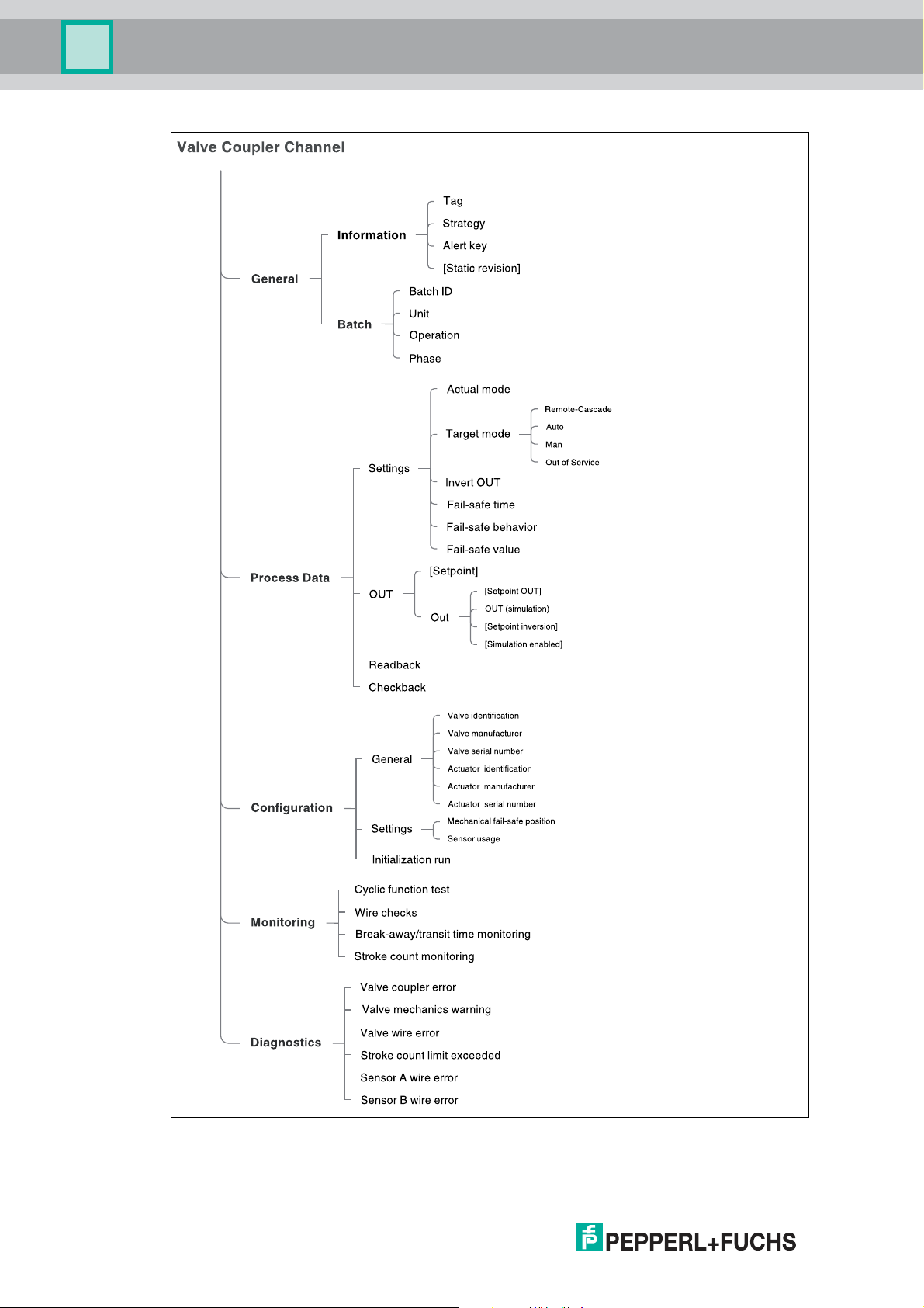
Multi-Input/Output Device
PACTware Multi-Input/Output Device Type Manager
68
Figure 10.8 DTM for valve coupler mode menu structure: Channel-specific
Parameters in square brackets [ ]: Online parameters only.
2018-07
Page 69

Multi-Input/Output Device
PACTware Multi-Input/Output Device Type Manager
10.3 Basic Device Setup in Sensor Input Mode
The “Basic device setup” is the initial setting you must make before going into any further
device setup or channel parameterization. In this section you set the MIO device up as a sensor
input. Depending on the settings you made, the subsequent menus change accordingly.
Figure 10.9 Channel "Basic Setup" tab: Select the device type
Section "Device mode":
Select the required device mode with the radio button.
More Information
For more information on the device modes, see chapter 2.2.
Section "Ident number":
Select the required ident number with the radio button.
Note!
Changing the PROFIBUS Ident Number in the Online Mode
If you use the menu command in online parameterization, a change of ident number selection
takes immediate effect. The device is automatically rebooted with the ident number selected.
More Information
For more information on ident numbers, see chapter 3.3.
2018-07
69
Page 70

Multi-Input/Output Device
PACTware Multi-Input/Output Device Type Manager
Setting Up the MIO Device as a Sensor Input
1. Activate the Sensor Input mode with the radio button.
2. Set the required ident number with the radio button.
3. Click on Next to adjust the channels as required.
Adjusting the Channels (1): Channel 1 as Binary Input
1. After selecting the sensor input mode, Next brings you to the section "Sensor Input – Adjustment of Channels 1, 4, 7, and 10".
70
Figure 10.10 Channel "Basic Setup" tab: Adjust channels of the first measurement loop
2. Set channel 1 to "Binary Input" and select the required sensor-on time from the pull-down
menu.
3. Enable/disable the channels 4, 7, and 10 as required. For enabled channels you can select
a suitable sensor-on time from the corresponding pull-down menu.
4. Click on Next. You move to the section "Sensor Input – Adjustment of Channels 2, 3, 5, 6, 8,
9, 11, and 12".
2018-07
Page 71
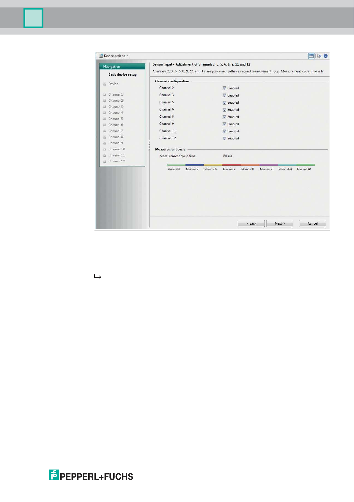
Multi-Input/Output Device
PACTware Multi-Input/Output Device Type Manager
Figure 10.11 Channel "Basic Device Setup" tab: Adjust channels of the second measurement
loop
5. Adjust the channels of the second measurement loop as required.
6. Click on Next.
The parameter settings are adjusted for the device and a summarized overview of all the
settings made is displayed.
7. Your basic device setup is complete. If you intend to change the settings, click on Change
Configuration or on Start to re-start the basic device setup.
2018-07
71
Page 72

Multi-Input/Output Device
PACTware Multi-Input/Output Device Type Manager
Adjusting the Channels (2): Channel 1 as Counter or Frequency Input
1. After selecting the sensor input mode, Next brings you to the section "Sensor Input – Adjust-
ment of Channels 1, 4, 7, and 10".
Figure 10.12 Channel "Basic Setup" tab set to Counter: Adjust channels of the first measurement
loop
2. Set channel 1 to "Counter" or to "Frequency Input".
The sensor-on time is automatically set to "Constantly on" and the channels 4, 7, and 10
are disabled.
3. Click on Next. You move to the section "Sensor Input – Adjustment of Channels 2, 3, 5, 6, 8,
9, 11, and 12".
72
2018-07
Page 73

Multi-Input/Output Device
PACTware Multi-Input/Output Device Type Manager
Figure 10.13 Channel "Basic Device Setup" tab: Adjust channels of the second measurement
loop
4. Adjust the channels of the second measurement loop as required.
5. Click on Next.
The parameter settings are adjusted for the device and a summarized overview of all the
settings made is displayed.
6. Your basic device setup is complete. If you intend to change the settings, click on Change
Configuration or on Start to restart the basic device setup.
More Information
For more information on the channel adjustment:
■
See chapter 4.4.3
■
See chapter 9
2018-07
73
Page 74

Multi-Input/Output Device
PACTware Multi-Input/Output Device Type Manager
10.3.1 Tab "Device Information"
This tab enables you to view or change device information as required, including general
information on the sensor and identification information needed throughout your process. The
settings apply to all sensor input modes.
Figure 10.14 "Device Information" tab
The tab "Device Information" contains the following information and parameters:
Section "General":
■
Tag: Free text field, enter a description of the device.
■
Device ID: Read-only, manufacturer-specific description of the device.
■
Manufacturer: Pepperl+Fuchs: Read-only, identification of the manufacturer of the
device.
Information Parameters in the Online Mode
In the online mode, the following read-only information is displayed.
Use this data as additional diagnostic information when contacting Pepperl+Fuchs.
■
Serial number: Serial number of the device
■
Software revision: Software revision number
■
Static revision: Incremental modification counter for counting each modification of a
parameter to document the status of modification of parameterization.
This parameter counts all changes in all device-specific online parameters.
74
2018-07
Page 75

Multi-Input/Output Device
PACTware Multi-Input/Output Device Type Manager
Section "Identification information":
■
Strategy: Free value field, enter value to use for configuration or diagnostics as a code
key for sorting or summarizing diagnostic information.
■
Alert key: Free value field, enter any value for sorting alarms or events that have been
generated. The value can contain the identification number of the plant unit. It helps to
identify the location (plant unit) of an event.
■
Description: Free text field, enter any information to describe the device as a measuring
point in the application.
■
Message: Free text field, enter any information to describe the device in the application or
plant.
■
Installation date: Free text field, enter the installation date of the device in the plant.
Adjusting the Device Information
1. Use the different fields to enter the information you require for your process.
2. Click on Apply.
More Information
For more information on the identification information, see chapter 3.3.
10.3.2 Device Tab "Diagnostics"
In the DTM, the tab "Diagnostics" enables you to configure the diagnostic behavior of the
device. The settings apply to all sensor input modes.
Figure 10.15 Device "Diagnostics" tab
2018-07
75
Page 76

Multi-Input/Output Device
PACTware Multi-Input/Output Device Type Manager
The tab "Diagnostics" contains the following parameters:
Section "Settings":
■
Diagnostic mode: Mode selector to be configured for status and diagnostic behavior.
Keep "Condensed diagnosis" or select "Classic diagnosis".
■
Hardware error: Type of diagnostic message and the mapping with the status this
message implies.
■
Memory error: Type of diagnostic message and the mapping with the status this
message implies.
Note!
Diagnostic Type for Cyclic Communication
Setting the diagnostic type to classic or condensed status in the tab Device determines the
diagnostic type of the cyclic communication between the device and the DTM.
The following settings determine the reaction of the device on manufacturer-specific diagnostic
events. For each error type you can determine how to diagnose it and determine the status that
the process value issues in case of the diagnosis:
Status that the process
value issues if the assigned
Error Type Diagnosis
Hardware error:
Memory error:
■
None
■
Maintenance
■
Maintenance demand
■
Maintenance alarm
■
Invalid process condition
■
Function check
diagnosis is active:
■
GOOD - OK
■
GOOD - Maintenance
required
■
GOOD - Maintenance
demanded
■
UNCERTAIN Maintenance demanded
■
BAD - Maintenance alarm
■
UNCERTAIN - Processrelated, no maintenance
■
BAD - Process-related, no
maintenance
■
BAD - Function check/
local override
■
GOOD - Function check
Diagnostic Parameters in the Online Mode
Diagnostic information is displayed additionally in the online mode in order to diagnose issues
or failures in real-time as they occur. Any diagnostic information issued by the DTM is
visualized through a NAMUR NE 107 icon in the following places:
■
Left navigation bar
■
Diagnostics tab
76
■
Top-level DTM information section "Overall status".
2018-07
Page 77

Multi-Input/Output Device
PACTware Multi-Input/Output Device Type Manager
NAMUR NE 107 Diagnostic Information
NAMUR NE 107 Icon Diagnostic Information
Good:
No failure
Maintenance required:
Maintenance demanded, Maintenance
Out of specification:
Invalid process condition
Failure:
Maintenance alarm
Adjusting the Diagnostics
1. Set or adjust the diagnostic information of the device as required.
2. Click on Apply to confirm.
More Information
For more information on diagnosis of the device, see chapter 6.3.
10.3.3 Sensor Input Channels 1 ... 12
The sensor input mode offers the use of up to 12 channels. Two sets of options for channel
settings are available for the 2 measurement loops.
2018-07
77
Page 78

Multi-Input/Output Device
PACTware Multi-Input/Output Device Type Manager
10.3.4 Tab "General"
This tab offers the option to view and enter general and batch information on the current
channel. The settings apply to all sensor input modes.
Figure 10.16 Channel "General" tab
The tab "General" contains the following parameters:
Section "Information":
■
Tag: Tag assignment option.
Free text field, assign a unique tag to each of the 12 channels of the MIO sensor input in
the plant or process.
■
Strategy: Code assignment option.
Free value field, assign a user-specific code value to each of the 12 channels of the MIO
sensor input. This code can be used for classifying and summarizing information, e. g., for
diagnosis reports.
■
Alert key: Code assignment option.
Free value field, assign a user-specific code value to each of the 12 channels of the MIO
sensor input. This code can be used for classifying and summarizing alarm messages
and events, i. e., for quick localization.
General Parameter in the Online Mode
The following parameters contain read-only information displayed in the online mode.
■
Static revision:
Incremental modification counter for counting each modification of a parameter to
document the status of parameterization modification.
This parameter counts changes in the online tabs General, Process Data, Configuration.
78
2018-07
Page 79

Multi-Input/Output Device
PACTware Multi-Input/Output Device Type Manager
Section "Batch":
■
Batch ID: Identification assignment option.
Free value field, assign an identifier for a batch process with distributed fieldbus systems
to enhance process identification.
■
Unit
Free value field, assign an identifier for a batch unit with distributed fieldbus systems to
enhance process identification. Example: Enter number of recipe unit procedure or of
unit.
■
Operation
Free value field, assign an identifier for a batch operation with distributed fieldbus systems
to enhance process identification. Example: Enter number of recipe operation.
■
Phase
Free value field, assign an identifier for a phase with distributed fieldbus systems to
enhance process identification. Example: Enter number of a recipe phase.
Adjusting the General Settings
1. Use the different fields to enter the information you require for your process.
2. Click on Apply to confirm.
10.3.5 Tab "Process Data" for a Binary Input
This tab contains all settings and parameters for the binary input of the channel and the failsafe settings.
Figure 10.17 Channel "Process Data" tab for the binary input
The tab "Process data" contains the following channel information and parameters:
2018-07
79
Page 80

Multi-Input/Output Device
PACTware Multi-Input/Output Device Type Manager
Section "Settings":
Process Data Parameters in the Online Mode
The following parameters contain read-only information displayed in the online mode.
■
Actual mode
Current mode of the channel. The mode can differ from the "Target mode".
Example: A different value or status is selected but the selection is not confirmed yet.
■
Target mode: Mode selection option per channel.
Choose the target mode of the output value for each of the 12 channels.
The following 3 modes are available:
• Auto: Automatic.
The measured value of the device is used as output value.
• Manual
Option to set the output value of the device manually.
• Out of service
The channel is not in use and the output value is BAD.
More Information
For more information on the modes of operation, see chapter 8.2.
■
Invert OUT: Determine whether the setpoint is logically inverted before writing to OUT in
Auto mode.
■
Fail-safe behavior: Defines the reaction of a device if a fault is detected.
• Use fail-safe value as OUT
• Use last valid OUT value
• Keep (wrong calculated) OUT value
■
Fail-safe value: Default value for the OUT parameter if a sensor or sensor electronics are
detected. Ensure that the fail-safe behavior is set accordingly.
More Information
For more information on the fail-safe behavior, see chapter 9.1.3.
Process Data Parameters in the Online Mode
The following parameters contain read-only information displayed in the online mode.
Section "OUT":
■
OUT: Process variable of the discrete input block in Auto mode. User-specified value
defined in the manual mode or during operation. When the diagnostic status turns to BAD,
the device uses the value specified in the fail-safe behavior.
The following 2 pull-down menus are active in case the actual mode is set to “Manual”. In
this case, you can make the settings for online diagnostic simulation purposes.
- OUT status type
- Alarm limits
80
■
Inverted
If this check box is shown as active, this confirms that the setpoint was logically inverted
before writing to OUT in the target modes "Auto".
■
Simulation enabled
If this check box is shown as active this confirms that the "Simulation" for this MIO sensor
input is enabled.
2018-07
Page 81

Multi-Input/Output Device
PACTware Multi-Input/Output Device Type Manager
More Information
For more information on OUT status types, see chapter 4.3.2.
For more information on simulation, see chapter 10.2.1.
Adjusting the Process Data Settings
1. Use the different fields and pull-down menus to enter the information you require for your
process.
2. Click on Apply to confirm.
10.3.6 Tab "Process Data" for a Frequency Input
This tab contains all settings and parameters for the frequency input of the channel and the failsafe settings.
Figure 10.18 Channel "Process Data" tab for the frequency input
The tab "Process data" contains the following channel information and parameters:
Section "Settings":
Process Data Parameters in the Online Mode
The following parameters contain read-only information displayed in the online mode.
■
Actual mode
Current mode of the channel. The mode can differ from the "Target mode".
Example: A different value or status is selected but the selection is not confirmed yet.
2018-07
81
Page 82

Multi-Input/Output Device
PACTware Multi-Input/Output Device Type Manager
■
Target mode: Mode selection option per channel.
Choose the target mode of the output value for each of the 8 channels.
The following 3 modes are available:
• Auto: Automatic.
The measured value of the device is used as output value.
• Manual
Option to set the output value of the device manually.
• Out of service
The channel is not in use and the output value is BAD.
More Information
For more information on the modes of operation, see chapter 8.2.
■
Fail-safe behavior: Defines the reaction of a device if a fault is detected.
• Use fail-safe value as OUT
• Use last valid OUT value
• Keep (wrong calculated) OUT value
■
Fail-safe value: Default value for the OUT parameter if a sensor or sensor electronics are
detected. Ensure that the fail-safe behavior is set accordingly.
More Information
For more information on the fail-safe behavior, see chapter 9.1.3.
Process Data Parameters in the Online Mode
The following parameters contain read-only information displayed in the online mode.
Section "OUT":
■
OUT: Process variable of the discrete input block in Auto mode. User-specified value
defined in the manual mode or during operation. When the diagnostic status turns to BAD,
the device uses the value specified in the fail-safe behavior.
The following 2 pull-down menus are active in case the actual mode is set to “Manual”. In
this case, you can make the settings for online diagnostic simulation purposes.
- OUT status type
- Alarm limits
■
Simulation enabled
If this check box is shown as active this confirms that the "Simulation" for this MIO sensor
input is enabled.
More Information
For more information on OUT status types, see chapter 4.3.2.
For more information on simulation, see chapter 10.2.1.
82
Adjusting the Process Data Settings
1. Use the different fields and pull-down menus to enter the information you require for your
process.
2. Click on Apply to confirm.
2018-07
Page 83

Multi-Input/Output Device
PACTware Multi-Input/Output Device Type Manager
10.3.7 Tab "Process Data" for a Counter
This tab contains all settings and parameters for the counter of the channel.
Figure 10.19 Channel "Process Data" tab for the counter
The tab "Process data" contains the following channel information and parameters:
Section "Settings":
Process Data Parameters in the Online Mode
The following parameters contain read-only information displayed in the online mode.
■
Actual mode
Current mode of the channel. The mode can differ from the "Target mode".
Example: A different value or status is selected but the selection is not confirmed yet.
■
Target mode: Mode selection option per channel.
Choose the target mode of the output value for each of the 8 channels.
The following 3 modes are available:
• Auto: Automatic.
The measured value of the device is used as output value.
• Manual
Option to set the output value of the device manually.
• Out of service
The channel is not in use and the output value is BAD.
More Information
For more information on the modes of operation, see chapter 8.2.
2018-07
83
Page 84

Multi-Input/Output Device
PACTware Multi-Input/Output Device Type Manager
Process Data Parameters in the Online Mode
The following parameters contain read-only information displayed in the online mode.
Section "OUT":
■
OUT: Process variable of the discrete input block in Auto mode. User-specified value
defined in the manual mode or during operation.
The following 2 pull-down menus are active in case the actual mode is set to “Manual”. In
this case, you can make the settings for online diagnostic simulation purposes.
- OUT status type
- Alarm limits
More Information
For more information on OUT status types, see chapter 4.3.2.
For more information on OUT reset counter (OUT_C_RESET), see chapter 4.2.
Adjusting the Process Data Settings
1. Use the different fields and pull-down menus to enter the information you require for your
process.
2. Click on Apply to confirm.
10.3.8 Tab "Configuration"
This tab gives you several text-only fields that you can fill in as your process requires. Configure
the sensor wire check. The settings apply to all sensor input modes.
84
Figure 10.20 Channel "Configuration" tab
The tab "Configuration" contains the following channel information and parameters:
2018-07
Page 85

Multi-Input/Output Device
PACTware Multi-Input/Output Device Type Manager
Section "Sensor":
■
Sensor configuration: Information on how the channel is currently configured.
Channel Parameters in the Online Mode
Sensor value
This is the original, unaltered value that the sensor returns, before it is passed to the function
block for further processing. If this value is "Bad", the fail-safe value is used as the OUT value
in the tab "Process Data".
■
Sensor wire check: Check boxes for enabling/disabling the following wire checks for the
sensor:
• Lead short circuit (not available for counter input mode!)
• Lead breakage
More Information
For more information on the sensor wire check, see chapter 9.3.1.
■
Sensor ID: Optional text field for identification information on the sensor of the current
channel.
■
Sensor serial number: Optional text field for identification information on the sensor of
the current channel.
■
Sensor manufacturer: Optional text field for identification information on the sensor of
the current channel.
Adjusting the Configuration Settings
1. Use the different text fields and check boxes to enter the information you require for your process.
2. Click on Apply to confirm.
2018-07
85
Page 86

Multi-Input/Output Device
PACTware Multi-Input/Output Device Type Manager
10.3.9 Channel Tab "Diagnostics"
This tab contains information on the sensor wire. Also, the type of diagnosis and a related
status can be configured. The settings apply to all sensor input modes.
Figure 10.21 Channel "Diagnostics" tab
The tab "Diagnostics" contains the following channel information and parameters:
Section "Settings":
The following settings determine the reaction of the device on manufacturer-specific diagnostic
events. For each error type you can determine how to diagnose it and determine the status that
the process value issues in case of the diagnosis:
86
2018-07
Page 87

Multi-Input/Output Device
PACTware Multi-Input/Output Device Type Manager
Error Type Diagnosis
Sensor wire error:
■
None
■
Maintenance
■
Maintenance demand
■
Maintenance alarm
■
Invalid process condition
■
Function check
Status that the process
value issues if the assigned
diagnosis is active:
■
GOOD - OK
■
GOOD - Maintenance
required
■
GOOD - Maintenance
demanded
■
UNCERTAIN Maintenance demanded
■
BAD - Maintenance alarm
■
UNCERTAIN - Processrelated, no maintenance
■
BAD - Process-related, no
maintenance
■
BAD - Function check/
local override
■
GOOD - Function check
Diagnostic Parameters in the Online Mode
Diagnostic information is displayed additionally in the online mode in order to diagnose issues
or failures in real-time as they occur. Any diagnostic information issued by the DTM is
visualized through a NAMUR NE 107 icon in the following places:
■
Left navigation bar
■
Diagnostics tab
■
Top-level DTM information section "Overall status".
NAMUR NE 107 Diagnostic Information
NAMUR NE 107 Icon Diagnostic Information
Good:
No failure
Maintenance required:
Maintenance demanded, Maintenance
Out of specification:
Invalid process condition
Failure:
Maintenance alarm
2018-07
87
Page 88

Multi-Input/Output Device
PACTware Multi-Input/Output Device Type Manager
Adjusting the Diagnostics
1. Set or adjust the diagnostic information of the channel as required.
2. Click on Apply to confirm.
More Information
For more information on diagnosis of the device, see chapter 6.3.
10.4 Basic Device Setup in Valve Coupler Mode
The “Basic device setup” is the initial setting you must make before going into any further
device setup or channel parameterization. In this section you set the MIO device up as a valve
coupler.
88
Figure 10.22 Channel "Basic Device Setup" tab: Select the device type
Section "Device mode":
Select the required device mode with the radio button.
More Information
For more information on the device modes, see chapter 2.2.
Section "Ident number":
Select the required ident number with the radio button.
2018-07
Page 89

Multi-Input/Output Device
PACTware Multi-Input/Output Device Type Manager
Note!
Changing the PROFIBUS Ident Number in the Online Mode
If you use the menu command in online parameterization, a change of ident number selection
takes immediate effect. The device is automatically rebooted with the ident number selected.
More Information
For more information on ident numbers, see chapter 3.3.
Setting Up the MIO Device as a Valve Coupler
1. Activate the Valve Coupler mode with the radio button.
2. Set the required ident number with the radio button.
3. Click on Next to confirm.
The parameter settings are adjusted for the device and a summarized overview of all the
settings made is displayed.
4. Your basic device setup is complete. If you intend to change the settings, click on Change
Configuration or on Start to restart the basic device setup.
10.4.1 Tab "Device Information"
This tab enables you to view or change device information as required, including general
information on the sensor and identification information needed throughout your process.
Figure 10.23 "Device Information" tab
The tab "Device Information" contains the following information and parameters:
2018-07
89
Page 90

Multi-Input/Output Device
PACTware Multi-Input/Output Device Type Manager
Section "General":
■
Tag: Free text field, enter a description of the device.
■
Device ID: Read-only, manufacturer-specific description of the device.
■
Manufacturer: Pepperl+Fuchs: Read-only, identification of the manufacturer of the
device.
Information Parameters in the Online Mode
In the online mode, the following read-only information is displayed.
Use this data as additional diagnostic information when contacting Pepperl+Fuchs.
■
Serial number: Serial number of the device
■
Software revision: Software revision number
■
Static revision: Incremental modification counter for counting each modification of a
parameter to document the status of modification of parameterization.
This parameter counts all changes in all device-specific online parameters.
Section "Identification information":
■
Strategy: Free value field, enter value to use for configuration or diagnostics as a code
key for sorting or summarizing diagnostic information.
■
Alert key: Free value field, enter any value for sorting alarms or events that have been
generated. The value can contain the identification number of the plant unit. It helps to
identify the location (plant unit) of an event.
■
Description: Free text field, enter any information to describe the device as a measuring
point in the application.
■
Message: Free text field, enter any information to describe the device in the application or
plant.
■
Installation date: Free text field, enter the installation date of the device in the plant.
Adjusting the Device Information
1. Use the different fields to enter the information you require for your process.
2. Click on Apply.
More Information
For more information on the identification information, see chapter 3.3.
90
2018-07
Page 91

Multi-Input/Output Device
PACTware Multi-Input/Output Device Type Manager
10.4.2 Device Tab "Diagnostics"
In the DTM, the tab "Diagnostics" enables you to configure the diagnostic behavior of the
device.
Figure 10.24 Device "Diagnostics" tab
The tab "Diagnostics" contains the following parameters:
Section "Settings":
■
Diagnostic mode: Mode selector to be configured for status and diagnostic behavior.
Keep "Condensed diagnosis" or select "Classic diagnosis".
■
Hardware error: Type of diagnostic message and the mapping with the status this
message implies.
■
Memory error: Type of diagnostic message and the mapping with the status this
message implies.
Note!
Diagnostic Type for Cyclic Communication
Setting the diagnostic type to classic or condensed status in the tab Device determines the
diagnostic type of the cyclic communication between the device and the DTM.
The following settings determine the reaction of the device on manufacturer-specific diagnostic
events. For each error type you can determine how to diagnose it and determine the status that
the process value issues in case of the diagnosis:
2018-07
91
Page 92

Multi-Input/Output Device
PACTware Multi-Input/Output Device Type Manager
Error Type Diagnosis
Hardware error:
Memory error:
■
None
■
Maintenance
■
Maintenance demand
■
Maintenance alarm
■
Invalid process condition
■
Function check
Status that the process
value issues if the assigned
diagnosis is active:
■
GOOD - OK
■
GOOD - Maintenance
required
■
GOOD - Maintenance
demanded
■
UNCERTAIN Maintenance demanded
■
BAD - Maintenance alarm
■
UNCERTAIN - Processrelated, no maintenance
■
BAD - Process-related, no
maintenance
■
BAD - Function check/
local override
■
GOOD - Function check
Diagnostic Parameters in the Online Mode
Diagnostic information is displayed additionally in the online mode in order to diagnose issues
or failures in real-time as they occur. Any diagnostic information issued by the DTM is
visualized through a NAMUR NE 107 icon in the following places:
■
Left navigation bar
■
Diagnostics tab
■
Top-level DTM information section "Overall status".
NAMUR NE 107 Diagnostic Information
NAMUR NE 107 Icon Diagnostic Information
Good:
No failure
Maintenance required:
Maintenance demanded, Maintenance
Out of specification:
Invalid process condition
92
Failure:
Maintenance alarm
2018-07
Page 93

Multi-Input/Output Device
PACTware Multi-Input/Output Device Type Manager
Adjusting the Diagnostics
1. Set or adjust the diagnostic information of the device as required.
2. Click on Apply to confirm.
More Information
For more information on diagnosis of the device, see chapter 6.3.
10.4.3 Valve Coupler Connections 1 ... 4
The valve coupler mode offers the use of up to 4 connections. The following options for
channel settings are identical for all 4 valve coupler connections.
10.4.4 Tab "General"
This tab offers the option to view and enter general and batch information on the current
channel.
Figure 10.25 Channel "General" tab
The tab "General" contains the following parameters:
Section "Information":
■
Tag: Tag assignment option.
Free text field, assign a unique tag to each of the 12 channels of the MIO sensor input in
the plant or process.
■
Strategy: Code assignment option.
Free value field, assign a user-specific code value to each of the 12 channels of the MIO
sensor input. This code can be used for classifying and summarizing information, e. g., for
diagnosis reports.
■
Alert key: Code assignment option.
Free value field, assign a user-specific code value to each of the 12 channels of the MIO
sensor input. This code can be used for classifying and summarizing alarm messages
2018-07
and events, i. e., for quick localization.
93
Page 94

Multi-Input/Output Device
PACTware Multi-Input/Output Device Type Manager
General Parameter in the Online Mode
The following parameters contain read-only information displayed in the online mode.
■
Static revision:
Incremental modification counter for counting each modification of a parameter to
document the status of parameterization modification.
This parameter counts changes in the online tabs General, Process Data, Configuration.
Section "Batch":
■
Batch ID: Identification assignment option.
Free value field, assign an identifier for a batch process with distributed fieldbus systems
to enhance process identification.
■
Unit
Free value field, assign an identifier for a batch unit with distributed fieldbus systems to
enhance process identification. Example: Enter number of recipe unit procedure or of
unit.
■
Operation
Free value field, assign an identifier for a batch operation with distributed fieldbus systems
to enhance process identification. Example: Enter number of recipe operation.
■
Phase
Free value field, assign an identifier for a phase with distributed fieldbus systems to
enhance process identification. Example: Enter number of a recipe phase.
Adjusting the General Settings
1. Use the different fields to enter the information you require for your process.
2. Click on Apply to confirm.
94
2018-07
Page 95

Multi-Input/Output Device
PACTware Multi-Input/Output Device Type Manager
10.4.5 Tab "Process Data"
This tab contains all settings and parameters to determine the mode the channel is supposed
to work in, a possible setpoint inversion, and the fail-safe settings. The tab offers readback and
checkback information.
Figure 10.26 Channel "Process Data" tab
The tab "Process data" contains the following channel information and parameters:
Section "Settings":
Process Data Parameters in the Online Mode
The following parameters contain read-only information displayed in the online mode.
■
Actual mode
Current mode of the channel. The mode can differ from the "Target mode".
Example: A different value or status is selected but the selection is not confirmed yet.
2018-07
95
Page 96

Multi-Input/Output Device
PACTware Multi-Input/Output Device Type Manager
■
Target mode: Mode selection option per channel.
Choose the target mode of the output value for each of the 12 channels.
For the channels 1 ... 4, the following 4 modes are available:
• Remote-Cascade: (RCas)
Mode to prevent the channel from automatically restarting when switching ON the
device or when the status of the setpoint value has become "bad".
• Auto: Automatic.
The measured value of the device is used as output value.
• Manual
Option to set the output value of the device manually.
• Out of service
The channel is not in use and the output value is BAD.
More Information
For more information on the modes of operation, see chapter 2.2.
For more information on remote-cascade (RCas), see chapter 8.2.4.
■
Invert OUT: Determine whether the setpoint is logically inverted before writing to OUT in
Auto or RCAS mode.
More Information
For more information on inverting the setpoint parameters, SP_D and RIN_D, see chapter 8.1.
■
Fail-safe time: Time in seconds from detection of failure of the actual used setpoint to the
action of the function block if the condition still exists.
■
Fail-safe behavior: Defines the reaction of a device if a fault is detected.
• Use mechanical fail-safe position
• Use last valid setpoint value
• Use fail-safe value as setpoint
■
Fail-safe value: Default value for the OUT parameter if a sensor or sensor electronics are
detected. Ensure that the fail-safe behavior is set accordingly.
More Information
For more information on the fail-safe behavior, see chapter 8.2.3 and see chapter 8.2.4.
For more information on the fail-safe mode, time, and value,
96
2018-07
Page 97

Multi-Input/Output Device
PACTware Multi-Input/Output Device Type Manager
Process Data Parameters in the Online Mode
The following parameters contain read-only information displayed in the online mode.
Section "OUT":
■
Setpoint
Current setpoint value and status of the channel.
Example: A different value or status is selected but the selection is not confirmed yet.
■
OUT: Process variable of the discrete output block in Auto and RCAS mode. Userspecified value defined in the manual mode or during operation. When the diagnostic
status turns to BAD, the valve or actuator goes to the position specified in the fail-safe
behavior defined by the mechanical fail-safe position.
The following 2 pull-down menus are active in case the actual mode is set to “Manual”. In
this case, you can make the settings for online diagnostic simulation purposes.
- OUT status type
- Alarm limits
■
Inverted
If this check box is shown as active, this confirms that the setpoint was logically inverted
before writing to OUT in the target modes "Auto" or "Remote-Cascade".
More Information
For more information on OUT_D, see chapter 4.3.1.
For more information on simulation, see chapter 10.2.1.
For information on the mechanical fail-safe position, see chapter 10.4.6.
Section "Readback":
Contains resulting read-only information on feedback of the valve position, the states of the
position inputs, and their lead faults.
■
Position of the actuator/valve
■
Sensor A wiring and sensor state
■
Sensor B wiring and sensor state
■
Status
■
Simulation enabled/disabled
More Information
For more information on RB_D, see chapter 4.3.1.
Section "Checkback":
Contains resulting read-only information on the detailed status, alarm, and fault signals of the
valve. For full documentation of this information refer to:
More Information
For more information on CB_D, see chapter 4.3.1.
2018-07
97
Page 98

Multi-Input/Output Device
PACTware Multi-Input/Output Device Type Manager
Adjusting the Process Data Settings
1. Use the different fields and pull-down menus to enter the information you require for your
process.
2. Click on Apply to confirm.
10.4.6 Tab "Configuration"
This tab gives you several text-only fields that you can fill in as your process requires.
Determine the mechanical fail-safe position, the sensor use and trigger the initialization run.
98
Figure 10.27 Channel "Configuration" tab
The tab "Configuration" contains the following channel information and parameters:
Section "General":
■
Valve identification Optional text field for identification information on the valve of the
current channel.
■
Valve manufacturer: Optional text field for identification information on the valve of the
current channel.
■
Valve serial number: Optional text field for identification information on the valve of the
current channel.
■
Actuator identification Optional text field for identification information on the actuator of
the current channel.
■
Actuator manufacturer: Optional text field for identification information on the actuator
of the current channel.
■
Actuator serial number: Optional text field for identification information on the actuator
of the current channel.
2018-07
Page 99

Multi-Input/Output Device
PACTware Multi-Input/Output Device Type Manager
Section "Settings":
■
Mechanical fail-safe position: Determines the safe position of the valve or actuator in
case of power loss.
More Information
For more information on the actuator fail action, see chapter 8.3.1.
■
Sensor usage: Maps the sensor position feedback signal with the valve positions
according to the requirements of your process:
• A (Closed: A=0, B=1; Intermediate: A=0, B=0; Open: A=1, B=1)
• B (Closed: A=1, B=0; Intermediate: A=1, B=1; Open: A=0, B=1)
• C (Closed: A=1, B=0; Intermediate: A=1, B=1; Open: A=0, B=1)
• D (Closed: A=0, B=1; Intermediate: A=1, B=1; Open: A=1, B=0)
• No position detection
More Information
For more information on the sensor usage, see chapter 8.3.2.
Section "Initialization run":
Channel Configuration Option in the Online Mode
Button "Initialization Run"
Use the button to initiate a device- and manufacturer-specific calibration procedure.
More Information
For more information on the initialization run, see chapter 6.4.
Adjusting the Configuration Settings
1. Use the different text fields, pull-down menus, and the button to enter the information you require for your process or trigger a calibration process.
2. Click on Apply to confirm.
2018-07
99
Page 100

Multi-Input/Output Device
PACTware Multi-Input/Output Device Type Manager
10.4.7 Tab "Monitoring"
This tab includes settings for the following monitoring activities: cyclic function test, wire check,
breakaway and transit time, stroke count.
100
Figure 10.28 Channel "Monitoring" tab
The tab "Monitoring" contains the following channel information and parameters:
Section "Cyclic function test":
Use this function test, e. g., for regular monitoring of a valve that is hardly triggered for correct
functioning.
■
Test enabled: Check box for enabling/disabling monitoring
■
Test interval: Up-down input fields for setting the test interval in hh:mm:ss
More Information
For more information on the cyclic function test, see chapter 8.4.4.
2018-07
 Loading...