

Page 1
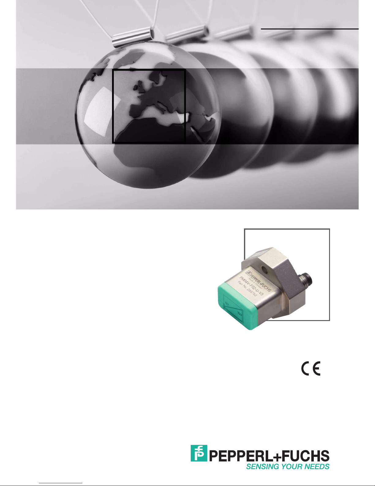
PMI14V-F112-...-U-...
F112 Inductive Positioning
System
FACTORY AUTOMATION
MANUAL
Page 2

With regard to the supply of products, the current issue of the following document is ap-
plicable: The General Terms of Delivery for Products and Services of the Electrical Indus-
try, published by the Central Association of the Electrical Industry (Zentralverband
Elektrotechnik und Elektroindustrie (ZVEI) e.V.) in its most recent version as well as the
supplementary clause: "Expanded reservation of proprietorship"
PMI14V-F112-...-U-...
Page 3

PMI14V-F112-...-U-...
3
1 Introduction................................................................................. 4
2 Declaration of Conformity.......................................................... 5
3 Safety........................................................................................... 6
3.1 Used Symbols ...................................................................................... 6
3.2 Intended Use ........................................................................................ 6
3.3 General Safety Instructions................................................................. 6
4 Product Description ................................................................... 8
4.1 Use and Application............................................................................. 8
4.2 Accessories .......................................................................................... 8
4.2.1 Damping Elements ............................................................................ 8
4.2.2 Connection Cable with Plug, 3-Wire................................................... 9
5 Installation................................................................................. 10
5.1 Safety Information.............................................................................. 10
5.2 Measuring Range of the PMI14V-...-U-... .......................................... 10
5.3 Preparation ......................................................................................... 11
5.4 Mounting ............................................................................................. 12
5.5 Connection ......................................................................................... 12
6 Commissioning......................................................................... 13
6.1 Commissioning in Line with Default Settings ................................. 13
6.2 Programming the Measuring Range ................................................ 13
6.3 Troubleshooting during Teach-in ..................................................... 14
7 Maintenance and Repair .......................................................... 15
7.1 Maintenance ....................................................................................... 15
8 Troubleshooting........................................................................ 16
8.1 What to Do in the Event of a Fault .................................................... 16
Page 4

2015- 12
4
PMI14V-F112-...-U-...
Introduction
1 Introduction
Congratulations
You have chosen a device manufactured by Pepperl+Fuchs. Pepperl+Fuchs develops,
produces and distributes electronic sensors and interface modules for the market of
automation technology on a worldwide scale.
Please read the operating instructions carefully before installing this device and putting it into
operation. The instructions and notes contained in this document will guide you step-by-step
through the installation and comm issioning procedures to ensure trouble-free use of this
product. By doing so, you:
■
Guarantee sa fe operation of the device
■
Can utilize the entire range of device functions
■
Avoid faulty operation and associated errors
■
Reduce costs associated with dow ntime and incidental repairs
■
Increase the effectiveness and operating efficiency of your plant.
Contact
If you have any questions about th e device, its functions, or accessories, please contact u s at:
Pepperl+Fuchs GmbH
Lilienthalstraße 200
68307 Mannheim
Telephone: +49 621 776-4411
Fax: +49 621 776-274411
E-Mail: fa-info@pepperl-fuchs.com
Note!
Store these instructions somewhere safe in order to have them available for futu re work on the
device.
Page 5

PMI14V-F112-...-U-...
Declaration of Conformity
2015- 12
5
2 Declaration of Conformity
This product was developed and manufactured under observance of the applicable European
standards and guidelines.
The product manufacturer, Pepperl+Fuchs GmbH, D-68307 Mannheim, has a certified quality
assurance system that conforms to ISO 9001.
Note!
A Declaration of Conformity can be requested from the manufacturer.
ISO9001
Page 6
2015- 12
6
PMI14V-F112-...-U-...
Safety
3 Safety
3.1 Used Symbols
Safety-relevant Symbols
Informative Symbols
Action
This symbol indicates a paragraph with instructions. You are prompted to perform an action or
a sequence of actions.
3.2 Intended Use
The F112 inductive positioning system is optimized for highly accurate, continuous position
detection. Based on the precise evaluation of several coil systems, the device combines a
proven inductive sensor with innovative m icrocontroller technology. The compact design of the
F112 enables position detection tasks to be carried out in a noncontact, wear-free process to a
measuring length of 14 mm, even in confined installation locations.
Only use recommended original accessories.
3.3 General safety instructions
Responsibility for planning, assembly, commissioning, operation, maintenance, and
dismounting lies with the plant operator.
Installation and commissioning of all devices must be performed by a trained professional only.
User modification and or repair are dangerous and will void the warranty and exclude the
manu facturer from any liability. If serious faults occur, stop using the device. Secure the device
against inadvertent operation. In the event of repairs, return the device to your local
Pepperl+Fuchs representative or sales office.
Danger!
This symbol indicates an imminent danger.
Non-observance will result in personal injury or death.
Warning!
This symbol indicates a possible fault or danger.
Non-observance may cause personal injury or serious property damage.
Caution!
This symbol indicates a possible fault.
Non-observance could interrupt the device and any connected systems and plan ts, or result in
their complete failure.
Note!
This symbol brings important information to your attention.
Note!
The optimum measurement accuracy is achieved at an actuator distance of 1 mm ... 2 mm.
Page 7

PMI14V-F112-...-U-...
Safety
2015- 12
7
Note!
Disposal
Electronic waste is hazardous waste. When disposing of the equipment, obser ve the current
statutor y requirements in the respective country of use, as well as local regulations.
Page 8

2015- 12
8
PMI14V-F112-...-U-...
Product Description
4 Product Description
4.1 Use and Application
The PMI14V-F112-...-U-... inductive positioning system is optimized for highly accurate,
continuous position detection.
Based on th e precise evaluation of several coil systems, the device combines a proven
inductive sensor with innovative microcontroller technology.
The compa ct design of the F112 enables position detection tasks to be carried out in a
noncontact and wear-free process to a measuring length of 14 mm. This includes installation
locations where space is limited.
With its integrated temperature compensation feature, the inductive positioning system is ideal
for use in harsh environments and for critical positioning tasks.
Due to the inductive functional principle, ferrites or magnets are not necessary as a
counterpart. As is the case with an inductive proximity switch, the dam ping element can be
made of any type of metal.
The benefits of the PMI14V-F112-...-U-... inductive positioning system include:
■
High resolution an d accuracy
■
Minimal temperature drift
■
Noncontact operation
■
Measuring range that can be taught in
■
Minimal susceptibility to interference due to the inductive functional principle
The PMI14V-F112-...-U-... inductive positioning system delivers a voltage signal between 0 V
... 10 V at the output that is proportional to the position of the dam ping element.
4.2 Accessories
Various accessories are available.
4.2.1 Damping Elements
We recommend using either the BT-F90-W or BT-F90-G damping element.
BT-F90-W Material: ST37 steel
ø 4,2
28
18
27
22
108
Page 9

PMI14V-F112-...-U-...
Product Description
2015- 12
9
Using Your Own Damping Elem ent
In principle, it is possible to use your own damping element. The damping element must have
the following proper ties to be able to make use of the sensor's specified accuracy:
Material: construction steel such as S235JR+AR (previous ly St37-2)
Dimensions as per BT-F90-W (L x W x H): ≥ 18 mm x 8 mm x ≥ 4 mm
Alternatively, the element must have the same dimensions as the BT-F90-G damping element.
4.2.2 Connection Cable with Plug, 3-Wire
Below is a list of 3-wire fem ale single-ended cordsets with a core cross-section of 3 x 0.25 m2
suitable for establishing the electrical connection for PMI14V-F112-...-U-... devices:
Other lengths on request.
BT-F90-G Material: ST37 steel
12 5
13
4
9
4
18
8
M4
22
ø 4.2
Note!
The exact width of the damping element of 8 mm must be observed. If the width of the damping
element deviates from this value, the position values will differ.
Type Straight Right angle Cable Lengths
V3-GM-2M-PVC X 2 m
V3-WM-2M-PUR X 2 m
V3-GM-5M-PVC X 5 m
V3-GM-5M-PUR X 5 m
V3-WM-2M-PVC X 2 m
V3-WM-2M-PUR X 2 m
V3-WM-5M-PVC X 5 m
V3-WM-5M-PUR X 5 m
Page 10

2015- 12
10
PMI14V-F112-...-U-...
Installation
5 Installation
5.1 Safety Information
5.2 Measuring Range of the PMI14V-...-U-...
General
On delivery, the measuring range of the PMI14V-F112-...-U-... is 14 mm. This is indicated by
the framed area at the front of the inductive positioning system.
It is possible to reduce the measuring range by param eterizing the sensor. When adjusting the
measuring range, the end point of the sensor is fixed; it is the starting point of the measuring
range that can be changed.
Figure 5.1
The starting point can be taught in within a range of 0 mm to 7 mm
Caution!
Risk of short circuit
Carrying out work while the system is energized may result in dam age to the device.
■
Always disconnect the supply voltage before carrying out work on the device.
■
Only connect the device to the supply voltage once all work has been completed.
U0 [V]Voltage at the analog output in volts
Pos.
[mm]
Position of the actuator in mm
0 7 14 Pos. [mm]
10
0
Uo [V]
Prog.
0V
10V
Page 11

PMI14V-F112-...-U-...
Installation
2015- 12
11
Definition of the Measuring Range/Position
The position of the dam ping element defined by the positioning system relates to half of the
width (center) of the damping element. The measuring range begins and ends with the half
coverage provided by the dam ping element when moving lengthwise.
Figure 5.2
Operating Instructions
If the damping element leaves the detection range of the positioning system, the last valid value
is retained at the voltage output until the damping element enters the valid area again. This is
illustrated in the figure below.
Figure 5.3
5.3 Preparation
Unpacking the unit
1. Check that all package contents are present and undamaged.
If anything is damaged, inform the shipper and contact the supplier.
Start of measuring range Measured position End of measuring range
Imprinted measuring range
Direction of movement of the damping element
Width B of the damping element
B/2
Damping
element
Page 12

2015- 12
12
PMI14V-F112-...-U-...
Installation
2. Check that all items are present and correct based on your order and the shipping
documents.
If you have any questions, please contact Pepperl+Fuchs.
3. Keep the original packing material in case you need to store or ship the u nit at a later time.
5.4 Mounting
■
A flush mount is possible in m etallic and nonmetallic environments
■
The distance between the measuring field (framed area at the front of the sensor) and the
mounting base or fastening screws on the damping element must be at least 3 mm.
Watch out for any protruding metal parts such as screw heads when mounting the device.
■
The damping element must be attached to the sensor at a right angle to guarantee the
relevant measurement accuracy.
■
The distance between the damping element and the sensor can be a maximum of 2.5 mm
and must be at least 1 mm.
Distance of the Damping Element
5.5 Connection
Connecting the Supply Voltage
To supply voltage to the sensor, proceed as follows:
1. Insert the prepared connection cable into the connector plug provided for this purpose on the
underside of the housing.
2. Screw the cap nut onto the connector plug as far as it will go. This ensures that the power
cable cannot be inadvertently pulled out.
3. Now connect the supply voltage to the cable provided.
The sensor is now ready for operation.
<
2.5 mm
>
10 mm
Page 13

PMI14V-F112-...-U-...
Commissioning
2015- 12
13
6 Commissioning
6.1 Commissioning in Line with Default Settings
1. Check that the distance between the damping element an d the sensor is correct.
2. Switch on the supply voltage. The operating indicator on the sensor lights up yellow.
The sensor will n ow function using the default parameters.
6.2 Programming the Measuring Range
Operating and Display Elements
The PMI14V-F112-...-U-... inductive positioning system features a small, slightly recessed push
button (1) on the back that is us ed to program the measuring range.
The measuring range starting point that is taught in is saved in the internal nonvolatile memory.
This ensures that the value remains available even if the power supply is disconnected.
Figure 6.1
Teaching in the Measuring Range
1. Position the damping element for position detection at the measuring range starting point to
be taught in. The geometric center of the damping e lement is crucial here.
2. Press and hold the push button with a thin object for at least 2 seconds. When doing so,
make sure that the damping element does not move.
The LED flashes yellow to indicate that the inductive positioning system is in Teach-in
mode. If the LED is not flashing yellow or flashes red, read the section "Troubleshooting
during Teach-in".
3. Confirm the taught-in starting point by pressing the push button again.
If the now yellow LED lights up continuously, the starting point has been taught in. The
end point of the measuring range remains unchanged. This point is marked by the area
labeled "10 V" on the front. If the LED flashes red, read the section "Troubleshooting during
Teach-in".
1 Push button for programming the m easuring range
2 Operating display: LED (yellow/red)
1
2
Page 14

2015- 12
14
PMI14V-F112-...-U-...
Commissioning
6.3 Troubleshooting during Teach-in
After pressing the push button once, the LED continues to light up
yellow
If there is no damping element in the defined detection range of the inductive positionin g
system, the device does not switch to "Teach-in mode".
Remedy: Position the dam ping element at the measuring range starting point at a maximum
distance of 2.5 mm.
After pressing the push button once, the LED flashes red
The damping element is located within the detection range of the inductive positioning system
at a position that is not valid for the Teach-in process. The LED flashes red for 20 seconds. The
sensor then returns to normal mode.
Remedy: Position the damping element within 0 mm ... 7 mm of the detection range. This is the
area within which you can teach in the meas uring range starting point.
In Teach-in mode, the LED changes from flashing yellow to flashing red
When calling up Teach-in mode, the damping element was in a valid position. Before the
measuring range s tarting point had been confirmed, the damping element left the detection
range of the inductive positioning system.
Remedy: Ensure that the damping element is not moved during the Teach-in process.
The LED flashes red after confirming the measuring range starting point
When calling up Teach-in mode, the damping element was in a valid position. Before the
measuring range starting point had been confirmed, the damping elem ent left the valid area for
Teach-in at the measuring range starting point (0 mm 7 m m).
Remedy: Ensure that the damping element is not moved during the Teach-in process.
Note!
Cancelation if Starting Point Not Confirmed
If the starting point that has been taught in is not confirmed within 120 seconds, the inductive
positioning system exits "Teach-in mode" and continues operation using the previous value.
Page 15

PMI14V-F112-...-U-...
Maintenance and Repair
2015- 12
15
7 Maintenance and Repair
7.1 Maintenance
The sensor's transmission properties are stable over long periods. For this reason, regular
adjustments to, a nd maintenance on the sensor itself, are not necessary. Nevertheless check in
the course of normal maintenance intervals that the sensor, the actuator and the connector are
securely attach ed. Also check that the connecting cable is intact and correctly routed.
Page 16

2015- 12
16
PMI14V-F112-...-U-...
Troubleshooting
8 Troubleshooting
8.1 What to Do in the Event of a Fault
Before requesting a service call, please check that the following actions have been taken:
■
The customer has tested the sys tem according to the checklist below.
■
Telephone assistance has been sought from the Ser vice Center to isolate the problem.
Checklist
■
If none of the above actions solves the problem, contact the Pepperl+Fuchs Service
Center. Have details of the model nu mber and firmware version of the sensor ready if
possible.
Fault Cause Remedy
"Operating indicator" LED
does n ot light up
The power supply is switched
off.
Check whether there is a
reason why the power supply
is switched off (installation or
maintenance work, etc.).
Switch on the power supply if
appropriate.
"Operating indicator" LED
does n ot light up
The plug is not connected to
the connector on the sensor.
Connect the plug to the
sensor and tighten the cap nut
by hand.
"Operating indicator" LED
does n ot light up
Wiring fault in the splitter or
switch cabinet.
Check the wiring carefully and
repair any wiring faults.
"Operating indicator" LED
does n ot light up
Supply cable to the sensor is
damaged.
Replace the damaged cable.
Object is not detected Sensor is too far away from
the item to be detected
Check the mounting and, if
necessary, adjust the sensor
to the correct distance
Page 17

Sub jec t t o m odi fic ati ons
Cop yri ght PE PPE RL+ FUC HS • Pri nte d i n G erm any
www.pepperl-fuchs.com
FACTORY AUTOMATION –
SENSING YOUR NEEDS
Worldwide Headquarters
Pepperl+Fuchs GmbH
68307 Mannheim · Germany
Tel. +49 621 776-0
E-mail: info@de.pepperl-fuchs.com
USA Headquarters
Pepperl+Fuchs Inc.
Twinsburg, Ohio 44087 · USA
Tel. +1 330 4253555
E-mail: sales@us.pepperl-fuchs.com
Asia Pacific Headquarters
Pepperl+Fuchs Pte Ltd.
Company Registration No. 199003130E
Singapore 139942
Tel. +65 67799091
E-mail: sales@sg.pepperl-fuchs.com
/ DOCT-5019
12/2015
 Loading...