

Page 1
EXTA2-* Keyboard
Manual
Page 2

With regard to the supply of products, the current issue of the following document is applicable: The
General Terms of Delivery for Products and Services of the Electrical Industry, published by the Central
Association of the Electrical Industry (Zentralverband Elektrotechnik und Elektroindustrie (ZVEI) e.V.)
in its most recent version as well as the supplementary clause: "Expanded reservation of proprietorship"
Worldwide
Pepperl+Fuchs Group
Lilienthalstr. 200
68307 Mannheim
Germany
Phone: +49 621 776 - 0
E-mail: info@de.pepperl-fuchs.com
North American Headquarters
Pepperl+Fuchs Inc.
1600 Enterprise Parkway
Twinsburg, Ohio 44087
USA
Phone: +1 330 425-3555
E-mail: sales@us.pepperl-fuchs.com
Asia Headquarters
Pepperl+Fuchs Pte. Ltd.
P+F Building
18 Ayer Rajah Crescent
Singapore 139942
Phone: +65 6779-9091
E-mail: sales@sg.pepperl-fuchs.com
https://www.pepperl-fuchs.com
Page 3

EXTA2-* Keyboard
Contents
1 Safety .......................................................................................................................... 4
1.1 General ........................................................................................................... 4
1.2 Delivery, Transport, and Storage .................................................................. 4
1.3 Installation and Commissioning .................................................................. 4
1.4 Keyboard Marking.......................................................................................... 5
1.5 Repair and Servicing ..................................................................................... 6
1.5.1 Servicing............................................................................................................................. 6
1.6 Disposal.......................................................................................................... 7
1.7 Intended Use of the EXTA2 Keyboard.......................................................... 7
1.8 Symbols Used ................................................................................................ 8
2 Product Specifications.............................................................................................. 9
2.1 Function.......................................................................................................... 9
2.2 Technical Data EXTA2-*-*-K3* with Trackball, Intrinsically Safe ................ 9
2.3 Technical Data EXTA2-*-*-K4* with Touchpad, Intrinsically Safe............. 11
2.4 Technical Data EXTA2-*-*-K6* with Joystick, Intrinsically Safe............... 13
2.5 EXTA2 dimensions....................................................................................... 14
2.6 Accessories.................................................................................................. 15
3 Installation and Commissioning ............................................................................ 16
3.1 Mounting the Keyboard Connecting Cable to a PC.................................. 16
3.2 Installation Instructions for Hazardous-Location EMC Cable Glands.... 19
3.3 Housing design keyboard ........................................................................... 20
3.3.1 Keyboard for Panel mounting (Housing Version -N) .......................................................... 21
3.3.2 Desktop Keyboard (Housing Version -T, e. g., for VisuNet)................................................ 22
3.3.3 Keyboard Mounting Options for Housing Version -F ......................................................... 25
4 Appendix .................................................................................................................. 30
4.1 Chemical Resistances................................................................................. 30
4.1.1 Chemical Resistance of Keyboard Foil ............................................................................. 30
4.1.2 Chemical resistance of the trackball, keyboard variante EXTA2-K3 .................................. 31
4.2 Typecode ...................................................................................................... 32
2021-01
3
Page 4

EXTA2-* Keyboard
Safety
1 Safety
1.1 General
Responsibility for planning, assembly, commissioning, operation, maintenance, and dismounting lies with the plant operator.
Installation und Inbetriebnahme aller Geräte dürfen nur von Fachpersonal durchgeführt
werden.
Protection of operating personnel and the system is not ensured if the product is not used in
accordance with its intended use.
Observe the applicable laws and regulations regarding the intended use of the device. The
devices are only approved for proper use for the intended purpose. Improper use will void any
warranty and liability claims.
The corresponding datasheets, declarations of conformity, and/or EC-type examination certificates form an integral part of this document. The data sheet contains the electronic data of the
EC-type-examination certificate.
These documents can be found at www.pepperl-fuchs.com or contact your local Pepperl+Fuchs representative.
1.2 Delivery, Transport, and Storage
Check the packaging and contents for damage.
Check if you have received every item and if the items received are the ones you ordered.
Keep the original packaging. Always store and transport the device in the original packaging.
Always store the device in a clean and dry location. Observe the permissible storage temperature (see datasheet).
1.3 Installation and Commissioning
Prior to mounting, installation, and commissioning of the device you should make yourself
familiar with the device and carefully read the instruction manual.
Installing alongside Intrinsically Safe Circuits
The intrinsically safe circuits of the devices may be installed in hazardous areas. In such cases,
they must be securely isolated from all non-intrinsically safe circuits.
The intrinsically safe current circuits must be installed in accordance with the applicable installation regulations.
If intrinsically safe field devices are connected to the intrinsically safe circuits in associated
devices, the respective maximum values of these field devices and the associated devices
must be observed to ensure explosion protection (verification of intrinsic safety). EN 6007914/IEC 60079-14 must be taken into account. The "National Foreword" (Nationale Vorwort) of
DIN EN 60079-14/VDE 06165 Part 1 must be observed if the device is used in Germany.
The nameplate must not be removed.
The device must be de–energized during installation and servicing. The keyboard/mouse must
not be connected to the supply voltage until the mounting and connection processes have
been fully completed.
Individually accessible non-grounded metal parts can become electrostatically charged. The
determined capacitance exceeds the required value according to IEC/EN 60079-0. The determined capacitance is specified in the technical data.
Information on electrostatic hazards can be found in the technical specification IEC/TS 6007932-1.
2021-01
4
Page 5
EXTA2-* Keyboard
Safety
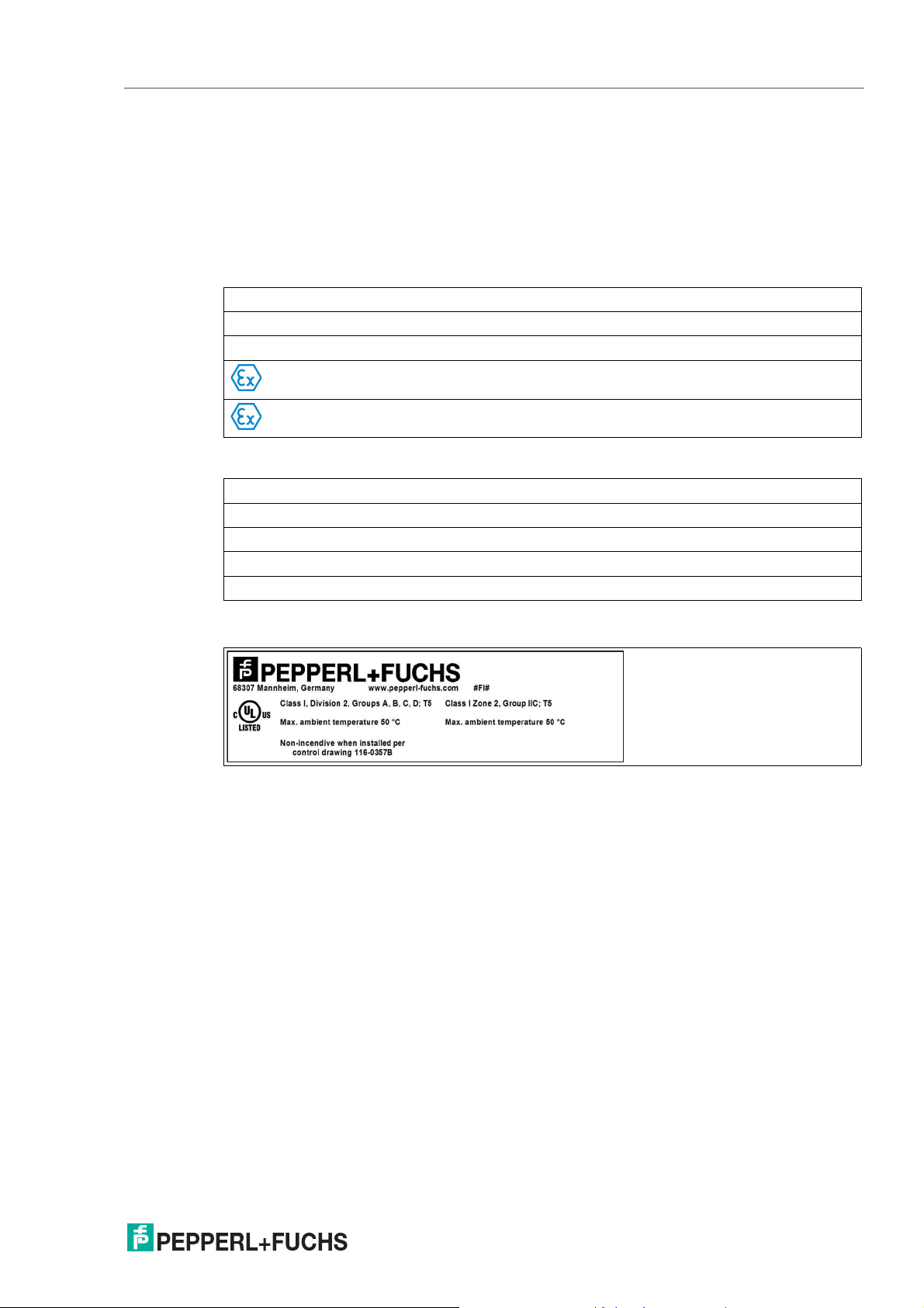
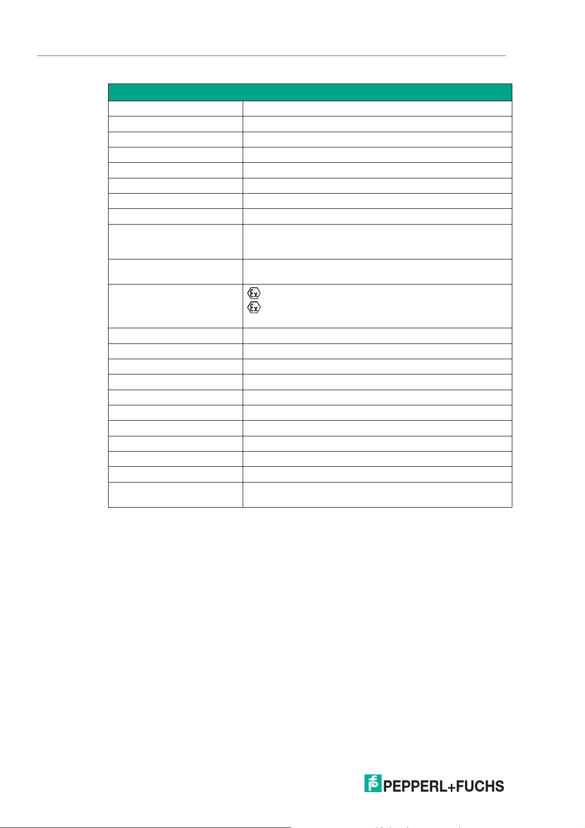
1.4 Keyboard Marking
EXTA2-*
Pepperl+Fuchs
D-68307 Mannheim
www.pepperl-fuchs.com
Additional label acc. to ATEX
EXTA2-*
Zone 1 and Zone 21
BVS 07 ATEX E 163 X
II 2G Ex ib IIC T4 Gb
II 2D Ex ib IIIB T135°C Db
Additional label acc. to IECEx
EXTA2-*
Zone 1 and zone 21
IECEx BVS 08.0022X
Ex ib IIC T4 Gb
Ex ib IIIB T135°C Db
Additional UL listing EXTA2-K-T and EXTA2-K-F for K4 and K6 models
Figure 1.1
2021-01
5
Page 6
EXTA2-* Keyboard
Safety
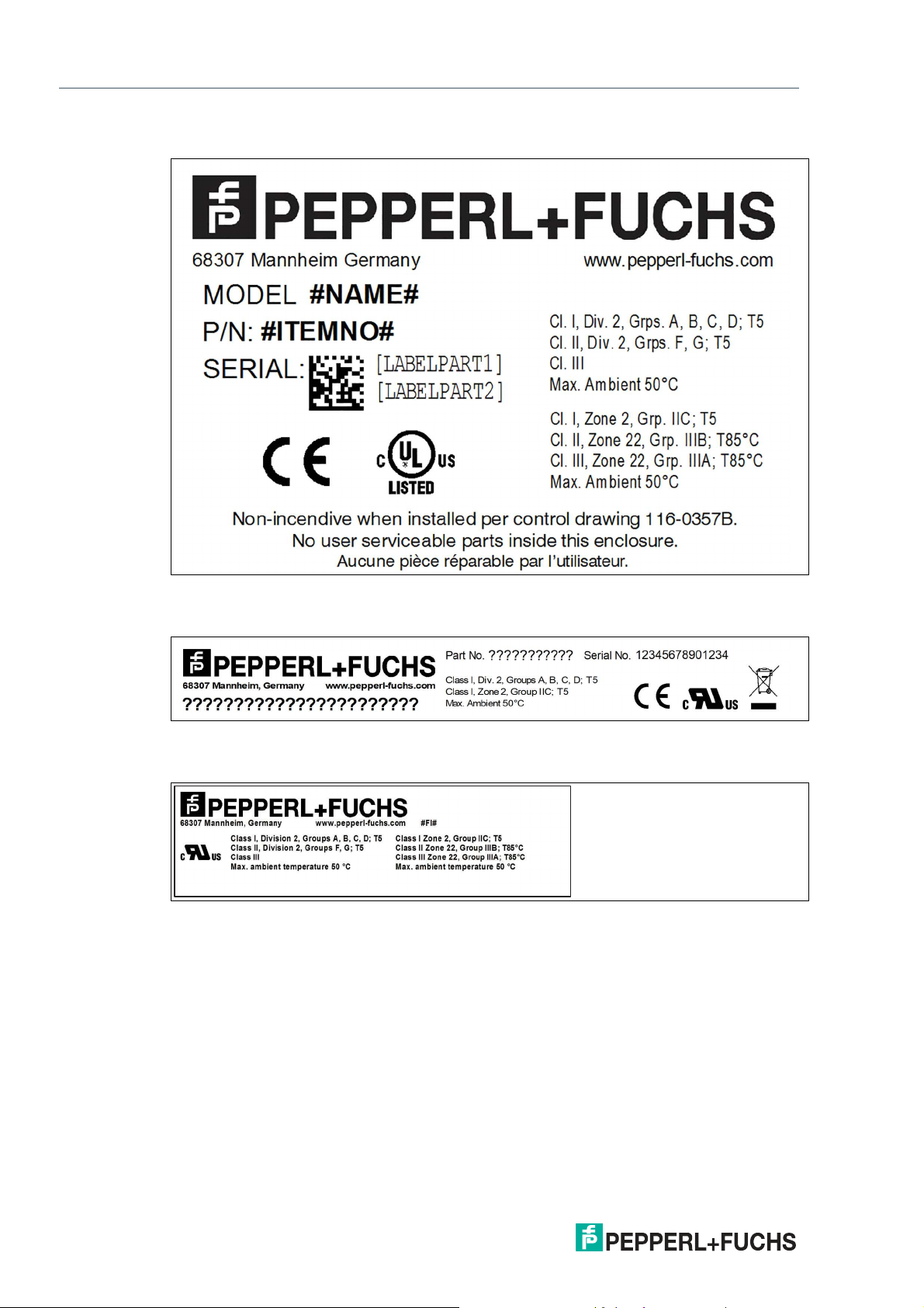
Additional UL listing EXTA2-J-F for K4 model
Figure 1.2
Additional UL recognition EXTA2-J-**- for K4 and K6 models
Figure 1.3
Additional UL recognition EXTA2-J-N for K4 models
Figure 1.4
1.5 Repair and Servicing
The device must not be repaired, changed, or manipulated. In case of failure, always replace
the device with an original device.
1.5.1 Servicing
If keyboards and mouse devices are used as parts of a system, standards, guidelines, or legal
requirements may exist that stipulate regular system tests.
Keyboard functionality should be checked at least twice a year or more frequently if the keyboard is subject to difficult conditions.
Do not clean the keyboard with corrosive liquids.
Any contamination can cause the keyboard to malfunction or completely fail.
6
2021-01
Page 7

EXTA2-* Keyboard
Safety
1.6 Disposal
The devices and the packaging material must be disposed of in accordance with the current
applicable statutes and regulations in the respective country.
The devices do not contain any batteries that require separate disposal.
1.7 Intended Use of the EXTA2 Keyboard
EXTA2 is a PC keyboard with an optional control element for mouse functions (touchpad,
mechanical trackball, joystick). The keyboard has USB interfaces for intended use in Zone 1
and Zone 21 hazardous areas according to ATEX Directive 2014/34/EU and IECEx. The USB
interfaces of the keyboard and the control element for mouse functions are separated, intrinsically safe circuits. Both intrinsically safe circuits are led out either in one or two separate connection cables. The conncection cable corresponds to type "B" according IEC 60079-14
section 12.2.2.8. The cable has to be secured and effectively protected from damage. The
EXTA2 keyboard cannot be installed in locations where corrosive media may be used.
To avoid discharge processes, the keyboard may only be installed in areas where high electrostatic buildup due to dust is unlikely. To avoid electrostatic charging, the keyboard cannot be
covered or glued with foils.
The keyboard cannot be exposed to direct sunlight, unless it is equipped with the UV-resistant
foil option.
When connecting the EXTA2 keyboard to a VisuNet RM/PC, keep in mind that the USB connection is not hot swappable. Connect the keyboard cable when there is no voltage applied.
If circuits with type of protection Ex i are operated with non-intrinsically safe circuits, they must
no longer be used as circuits with type of protection Ex i.
2021-01
7
Page 8

EXTA2-* Keyboard
Safety
1.8 Symbols Used
Safety-Relevant Symbols
Danger!
This symbol indicates an imminent danger.
Non-observance will result in personal injury or death.
Warning!
This symbol indicates a possible fault or danger.
Non-observance may cause personal injury or serious property damage.
Caution!
This symbol indicates a possible fault.
Non-observance could interrupt the device and any connected systems and plants, or result in
their complete failure.
Informative Symbols
Note
This symbol brings important information to your attention.
Action
This symbol indicates a paragraph with instructions. You are prompted to perform an action or
a sequence of actions.
2021-01
8
Page 9
EXTA2-* Keyboard
Product Specifications
2 Product Specifications
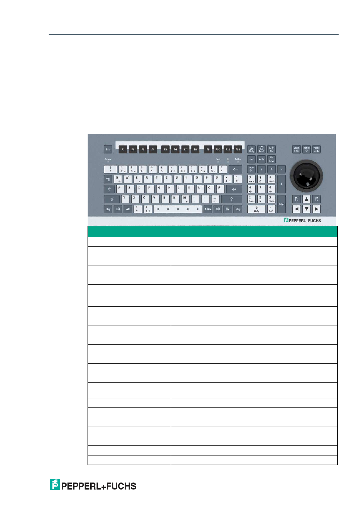
2.1 Function
The EXTA2 is a keyboard/mouse combination with USB interfaces, available in different versions. The intrinsically safe keyboards integrate different mouse systems. The outside dimensions are the same for all versions. The keyboards are designed for panel mounting or for
installation in a housing. The EXTA2 comes with an 8-pin connection cable included.
2.2 Technical Data EXTA2-*-*-K3* with Trackball, Intrinsically Safe
Technical Data EXTA2-*-*-K3*
General specifications
Type Keyboard with trackball
Supply
Rated voltage Ex i, via data line
Indicators/operating means
Keyboard 105 short stroke keys
Keyboard layout: US international, German, French, (further
keyboard layouts on demand)
Trackball
Diameter 50 mm
Material Phenolic resin (black)
Driver Microsoft® Mouse, USB
Interface
Interface type USB or PS/2 (PS/2 via adapter)
Directive conformity
Electromagnetic compatibility
Directive 2014/30/EU EN 61326-1:2013 (industrial locations); EN 61000-6-
RoHS
Directive 2011/65/EU (RoHS) EN 50581:2012-09
Conformity
Electromagnetic compatibility EN 61000-6-2:2005
Degree of protection IP65, if trackball is inactive. Undefined during motion.
Ambient conditions
2021-01
Ambient temperature 0 ... 50 °C (32 ... 122 °F)
4:2007+A1:2011
9
Page 10
EXTA2-* Keyboard
Product Specifications
Technical Data EXTA2-*-*-K3*
Storage temperature -20 ... 70 °C (-4 ... 158 °F)
Relative humidity max. 85 %, non-condensing
Mechanical specifications
Material anodized aluminum, Polyester foil
Mass 1.2 kg
Dimensions 482.6 mm x 177.8 mm x 45 mm
Cut out dimensions 450 mm x 152 mm
Cable length 5 m / 1.8 m, USB
Data for application in connection with hazardous
areas
EC-Type Examination Certificate
Group, category, type of protection
BVS 07 ATEX E 163 X
II 2G Ex ib IIC T4 Gb
II 2D Ex ib IIIB T135°C Db
Input
Voltage 5.4 V
Current 240 mA
Power 600 mW
Internal capacitance 24 µF
Internal inductance negligible
Directive conformity
Directive 2014/34/EU EN 60079-0:2012+A11:2013, EN 60079-11:2012
International approvals
IECEx approval IECEx BVS 08.0022X
Group, category, type of protection
Ex ib IIC T4 Gb, Ex ib IIIB T135°C Db
10
2021-01
Page 11
EXTA2-* Keyboard
Esc
F1 F2
F3
F4
F5
F6
F7
F8 F9 F10 F11 F12
1
Alt
AltGr
+
Rollen
Num
Einfg
Bild
Pos 1
Ende
Bild
Entf
/
-
*
!
Druck
Pause
S-Abf
Untbr
Enter
0
1 2
3
4
5
6
7 8 9
Pos 1
Einfg
Ende
Bild
Bild
Entf
StrgStrg
2
3
4
$
5
%
6 7 8 9)0
Q
A S D F G H
J
K L
W E R T Z U I O P
§
X
C
V B N
M
,
.
NumPower
Rollen
,
Y
^
°
<
>
|
µ
€
@
;
:
/
-
_
Ö Ä
}
][
{
Ü
*
+
\
#
‘
2 3
&
(
=
?
ß
Product Specifications
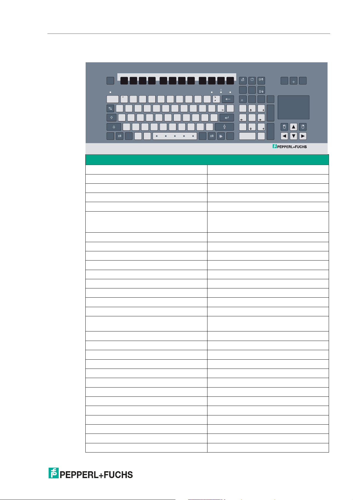
2.3 Technical Data EXTA2-*-*-K4* with Touchpad, Intrinsically Safe
2021-01
Technical Data EXTA2-*-*-K4*
General specifications
Type Keyboard with touchpad
Supply
Rated voltage Ex i, via data line
Indicators/operating means
Keyboard 105 short stroke keys
Keyboard layout: US international, German,
French, (further keyboard layouts on demand)
Touchpad
Active Principle capacitive
Resolution 40 Pts./mm
Dimensions 66 x 50
Driver Microsoft Mouse ® , USB
Interface
Interface type USB or PS/2 (PS/2 via adapter)
Directive conformity
Electromagnetic compatibility
Directive 2014/30/EU EN 61326-1:2013 (industrial locations) ; EN
61000-6-4:2007+A1:2011
RoHS
Directive 2011/65/EU (RoHS) EN 50581:2012-09
Conformity
Electromagnetic compatibility EN 61000-6-2:2005
Degree of protection IP66
Ambient conditions
Ambient temperature -20 ... 50 °C (-4 ... 122 °F)
Storage temperature -20 ... 70 °C (-4 ... 158 °F)
Relative humidity max. 85 % , non-condensing
Mechanical specifications
Material anodized aluminum , Polyester foil
Mass 1.2 kg
Dimensions 482.6 mm x 177.8 mm x 45 mm
11
Page 12

EXTA2-* Keyboard
Product Specifications
Technical Data EXTA2-*-*-K4*
Cut out dimensions 450 mm x 152 mm
Cable length 5 m / 1.8 m, USB
Data for application in connection with
hazardous areas
EC-Type Examination Certificate BVS 07 ATEX E 163 X
Group, category, type of protection
Input
Voltage 5.4 V
Current 240 mA
Power 600 mW
Internal capacitance 24 µF
Internal inductance negligible
Directive conformity
Directive 2014/34/EU EN 60079-0:2012+A11:2013, EN 60079-
International approvals
UL approval UL listing/recognition: E190294
IECEx approval IECEx BVS 08.0022X
Group, category, type of protection Ex ib IIC T4 Gb, Ex ib IIIB T135°C Db
II 2G Ex ib IIC T4 Gb
II 2D Ex ib IIIB T135°C Db
11:2012
12
2021-01
Page 13
EXTA2-* Keyboard
Product Specifications
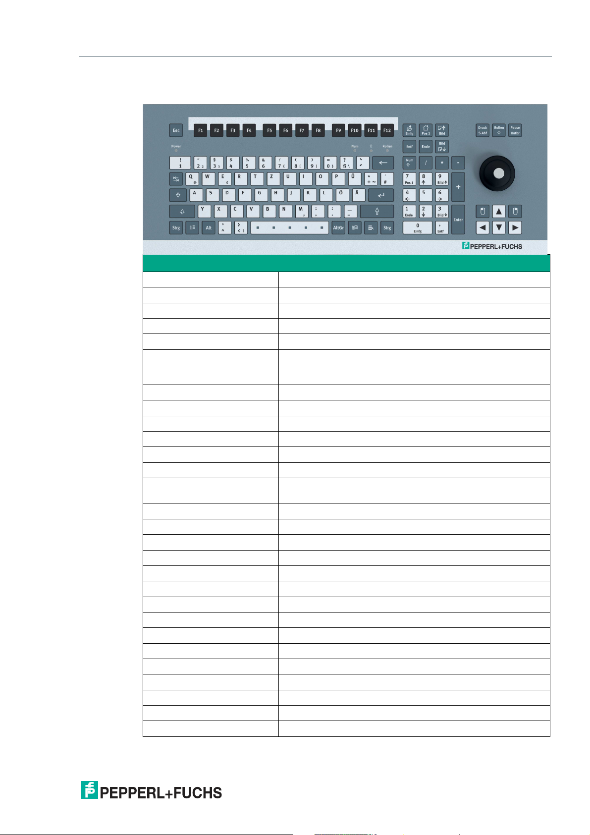
2.4 Technical Data EXTA2-*-*-K6* with Joystick, Intrinsically Safe
Technical Data EXTA2-*-*-K6*
General specifications
Type Keyboard with joystick
Supply
Rated voltage Ex i, via data line
Indicators/operating means
Keyboard 105 short stroke keys
Joystick
Driver Microsoft Mouse ® , USB
Interface
Interface type USB or PS/2 (PS/2 via adapter)
Directive conformity
Electromagnetic compatibility
Directive 2014/30/EU EN 61326-1:2013 (industrial locations) ; EN 61000-6-
RoHS
Directive 2011/65/EU (RoHS) EN 50581:2012-09
Conformity
Electromagnetic compatibility EN 61000-6-2:2005
Degree of protection IP65
Ambient conditions
Ambient temperature -20 ... 50 °C (-4 ... 122 °F)
Storage temperature -20 ... 70 °C (-4 ... 158 °F)
Relative humidity max. 85 % , non-condensing
Mechanical specifications
Material anodized aluminum , Polyester foil
Mass 1.2 kg
Dimensions 482.6 mm x 177.8 mm x 45 mm
Cut out dimensions 450 mm x 152 mm
Cable length 5 m / 1.8 m, USB
Keyboard layout: US international, German, French, (further
keyboard layouts on demand)
4:2007+A1:2011
2021-01
13
Page 14
EXTA2-* Keyboard
Product Specifications
Technical Data EXTA2-*-*-K6*
Data for application in connection with hazardous
areas
EC-Type Examination Certificate
Group, category, type of protection
Input
Voltage 5.4 V
Current 240 mA
Power 600 mW
Internal capacitance 24 µF
Internal inductance negligible
Directive conformity
Directive 2014/34/EU EN 60079-0:2012+A11:2013, EN 60079-11:2012
International approvals
UL approval UL listing/recognition: E190294
IECEx approval IECEx BVS 08.0022X
Group, category, type of protection
BVS 07 ATEX E 163 X
II 2G Ex ib IIC T4 Gb
II 2D Ex ib IIIB T135°C Db
Ex ib IIC T4 Gb, Ex ib IIIB T135°C Db
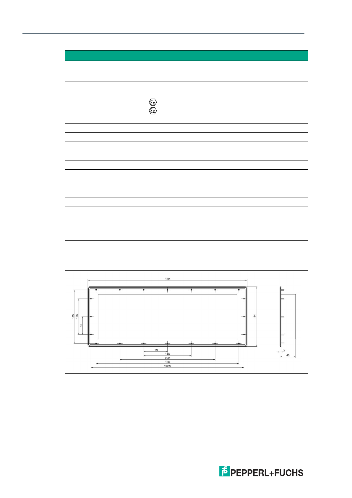
2.5 EXTA2 dimensions
Keyboard dimensions
Figure 2.1
The EXTA2 comes with an 8-pin connection cable included.
14
2021-01
Page 15

EXTA2-* Keyboard
Product Specifications
2.6 Accessories
If you use the EXTA2 as a stand-alone keyboard, an additional barrier is required.
Order Code Description Part Number
SK-PC-Z1D1-UU1-10-HS 2-channel Barrier with intrinsi-
cally safe USB outputs for
548307
&mouse & keyboard (EXTA2)
Approval: ATEX/IECEx Zone
1/21
Inputs: 2x USB 2.0
Outputs: 2x USB 2.0 Ex ib
Mounting: DIN rail
Figure 2.2
For further information on installing the EXTA2 Keyboard with the SK-PC-Z1D1-UU1-10-HS
barrier please refer to the SK-PC-Z1D1-UU1-10-HS manual at pepperl-fuchs.com.
2021-01
15
Page 16

EXTA2-* Keyboard
Installation and Commissioning
3 Installation and Commissioning
3.1 Mounting the Keyboard Connecting Cable to a PC
Note
For installation and connection in North America, refer to Control Drawing 116-0357C.
Connecting the Keyboard to a PC via the Keyboard Connecting Cable
Connect the wires of the keyboard connecting cable as shown in the following table.
Keyboard and Mouse (EXTA2-*-*-K*) Core Assignment
Assignment Color coding
Keyboard Ui green
D+ brown
D- grey
GND yellow
Mouse Ui red
D+ white
D- pink
GND blue
Note
Torque Specifications for Keyboard Lid
After connecting the keyboard, tighten the screws on the EXTA2 lid to a torque of 0.5 Nm (4.4 in
lb).
16
2021-01
Page 17

EXTA2-* Keyboard
Installation and Commissioning
Connecting the Keyboard to a PC via Barrier SK-PC-Z1D1-UU1-10-HS for
Stand-alone applications
1.
Plug the USB plugs of the keyboard cables into the USB ports of the barrier. Use the USB ports
on the face labeled with "intrinsically safe."
2.
Plug the USB plugs of the enclosed USB cables into the USB ports of the barrier. Use the USB
ports on the face labeled with "not intrinsically safe."
Figure 3.1 Installation requirements for the barrier in Zone 2 (gas) option 1
Figure 3.2 Installation requirements for the barrier in Zone 2 (gas) option 2
For further information on how to install the Keyboard in Stand-alone applications via Barrier
SK-PC-Z1D1-UU1-10-HS please refer to the SK-PC-Z1D1-UU1-10-HS manual.
2021-01
17
Page 18

EXTA2-* Keyboard
Installation and Commissioning
Equipotential Bonding
1.
The shielding of the keyboard cable must be connected in the cable gland of the PC/display
(VisuNet) (refer to VisuNet manual). Before doing this, open the cable clip (1) and remove the
cable protective tube (2).
End of the Keyboard Cable (Attached to the Keyboard)
Danger!
Explosion Hazard
Risk of fatal injury and severe property damage.
The housing must always be connected to the PE. There are 2 possibilities:
Connection via cable shielding of the connecting cable.
Built into a metal housing that is connected to the PE.
• (1) cable clip
• (2) cable protective tube
2.
Install the keyboard in a metal housing that is connected to PE.
18
2021-01
Page 19

EXTA2-* Keyboard
Installation and Commissioning
3.2 Installation Instructions for Hazardous-Location EMC Cable
Glands
Power supply cables for the Ex e Ethernet and the RS-485 or TTY Ex e data interface, the Ex i
keyboard, and the Ex i scanner must be shielded to ensure sufficient immunity to interference
(EMC). Connect the cable shielding to the VisuNet RM/PC according to the following installation instructions:
Step 1
• Isolate the cable.
• Expose the braid.
• Remove the braid and insulation little by little.
• With thin cables, the braid can be folded back
over the insulation sheath.
• Insert the cable into the gland until the braid
reaches the contact point.
• Tighten the cable gland.
Step 2
• Guide the cable through the lock nut.
• Guide the cable into the terminal insert.
• Fold the braid over the insert.
• The braid must overlap the O-ring by about 2
mm
2021-01
19
Page 20

EXTA2-* Keyboard
Installation and Commissioning
Step 3
• Fit the terminal insert into the intermediate
gland.
• Assemble the cable gland.
Internal view of the assembled cable gland.
3.3 Housing design keyboard
There are different possibilities to mount the keyboards.
1. Panel mounting (Housing version -N)
2. The keyboard is mounted in a desktop housing. (Housing version -T)
3. Different Mounting Options (Housing version -F)
20
2021-01
Page 21

EXTA2-* Keyboard
Installation and Commissioning
3.3.1 Keyboard for Panel mounting (Housing Version -N)
Figure 3.3
Safety Information for Installation in North America
When installed in North America, EXTA2-J-N models are only suitable for use in the following
locations:
• Class I, Division 2, Groups A, B, C, and D
• Class II, Division 2, Groups F and G
• Class III
• Nonhazardous locations
The following safety information applies for installation in North America:
Danger!
Explosion Hazard
Risk of fatal injury and severe property damage.
Do not substitute components. Substitution of any component may impair suitability for Class I,
Division 2 and Class II, Division 2.
Devices must also be installed in a suitable enclosure.
Warning!
Maximum Air Temperature
Risk of device damage.
Devices are suitable for a maximum surrounding air temperature of 50 °C.
2021-01
21
Page 22

EXTA2-* Keyboard
450
146
292
438
469,6
20 x
Ø 5
110
164,8
152
Installation and Commissioning
Assembly of the keyboard with cover at the back: Cutout
Figure 3.4
Note
Torque Specifications
Torque the screws for the EXTA2 keyboard and housing interface to 0.4 Nm (3.5 in lb).
3.3.2 Desktop Keyboard (Housing Version -T, e. g., for VisuNet)
22
Figure 3.5
2021-01
Page 23

EXTA2-* Keyboard
265
287
(1)
50
530
80
92
Installation and Commissioning
Desktop Keyboard Dimensions
Figure 3.6
• (1) protective earth bolt
Grounding the Desktop Keyboard
1.
Ground the Keyboard Housing with the protective earth bolt. Use the following grounding
concept. (The PE wire is not included in the scope of delivery and must be provided in the right
length.)
Figure 3.7
2.
Fasten the hardware with a torque of 7.5 Nm.
2021-01
23
Page 24
EXTA2-* Keyboard
Installation and Commissioning
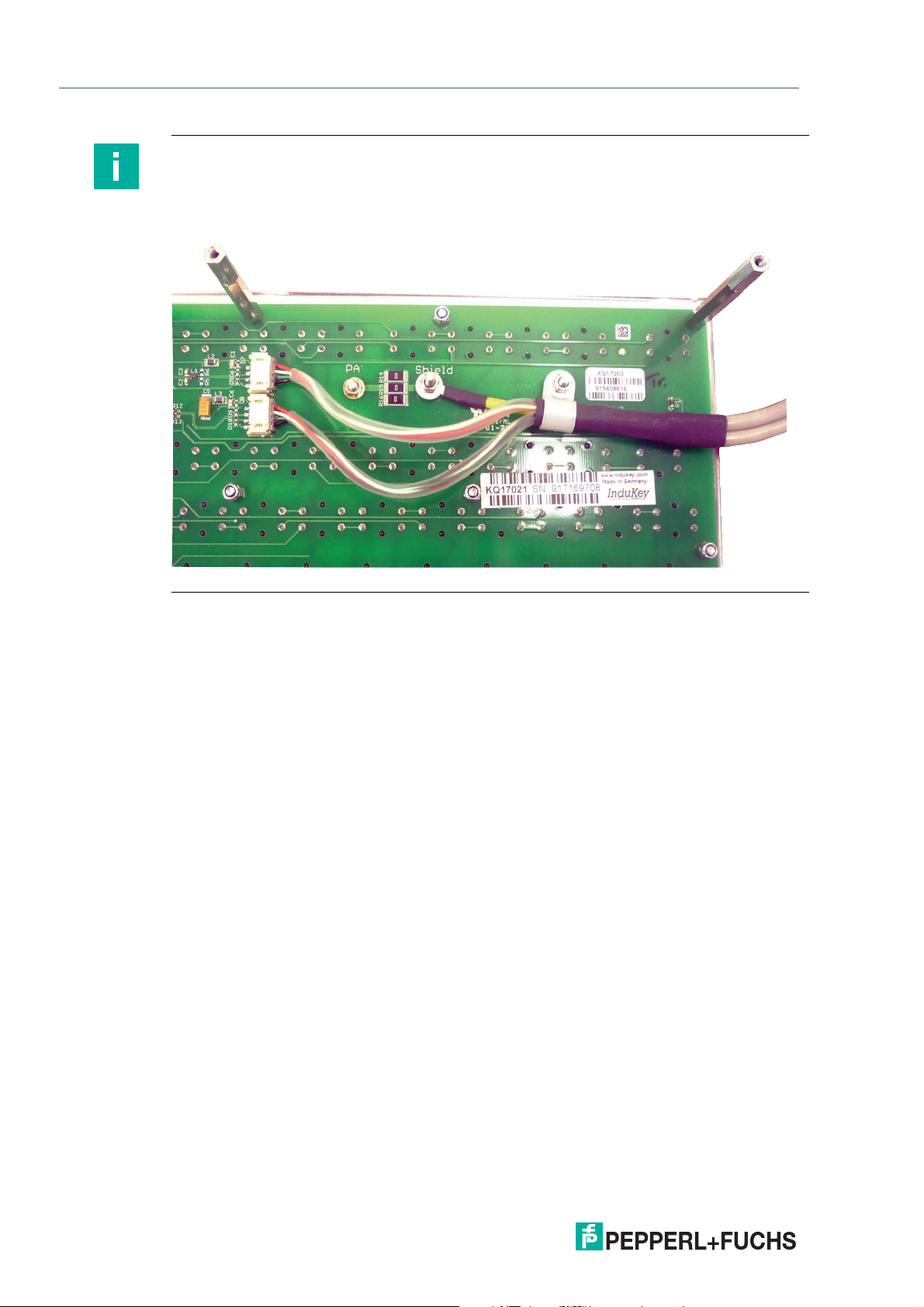
Note
To simplifiy keyboard mounting, you can remove the cables from the keyboard PCB. After you
have mounted the keyboard, reattach all cables properly—including the PA cable. Tighten
protective earth to a torque of 0.15 Nm (1.3 in lb). Tighten the cable clip to a torque of 0.3 Nm
(2.6 in lb).
Figure 3.8
24
2021-01
Page 25

EXTA2-* Keyboard
480
582
185
240
58
1
58
~
30°
3
97
153
Installation and Commissioning
3.3.3 Keyboard Mounting Options for Housing Version -F
Dimensions Mounting Option -G
Figure 3.9
Figure 3.10 Dimensiondrawing
2021-01
25
Page 26

EXTA2-* Keyboard
Installation and Commissioning
Dimensions Mounting Option -F
Figure 3.11
Figure 3.12
26
2021-01
Page 27

EXTA2-* Keyboard
Installation and Commissioning
Dimensions Mounting Option -L
Figure 3.13
Figure 3.14
2021-01
27
Page 28

EXTA2-* Keyboard
Installation and Commissioning
Dimensions Mounting Option -H
Figure 3.15
Figure 3.16 Dimensiondrawing
28
2021-01
Page 29

EXTA2-* Keyboard
Ø 26
Ø 17
120°
Ø 5.5
Installation and Commissioning
Figure 3.17 Drilling pattern for the wall
2021-01
29
Page 30

EXTA2-* Keyboard
Esc
F1 F2
F3
F4
F5
F6
F7
F8 F9 F10 F11 F12
1
Alt
AltGr
+
Rollen
Num
Einfg
Bild
Pos 1
Ende
Bild
Entf
/
-
*
!
Druck
Pause
S-Abf
Untbr
Enter
0
1 2
3
4
5
6
7 8 9
Pos 1
Einfg
Ende
Bild
Bild
Entf
StrgStrg
2
3
4
$
5
%
6 7 8 9
)
0
Q
A S D F G H
J
K L
W E R T Z U I O P
§
X
C
V B N
M
,
.
NumPower
Rollen
,
Y
^
°
<
>
|
µ
€
@
;
:
/
-
_
Ö Ä
}
][
{
Ü
*
+
\
#
‘
2 3
&
(
=
?
ß
Appendix
4 Appendix
4.1 Chemical Resistances
4.1.1 Chemical Resistance of Keyboard Foil
Warning!
Not all models are resistant to UV light!
Destruction of keyboard foil.
Unless the keyboard is equipped with the UV-resistant foil option, do not expose the keyboard
foil to direct sunlight. EXTA2-*U models have a UV-resistant foil and are suitable for outdoor
use. See the typecode, see chapter 4.2.
Antimicrobial resistance of keyboard foil
30
The keyboard foil is manufactured from a biaxially alignned polyester-based material and therefore has a greater resistance to solvents. The foil is stronger and more durabe than other standard foils used on keyboards and front panels, such as polycarbonate and PVC.
The keyboard foil is resistant against the following substances (Test method:
DIN42115):
Alcohols Hydrocarbons
Dilute acids Ketones
Dilute alkalis Household cleaners
Esters
The keyboard foil is resistant against the following substances (Test method: AATCC
test method 100)::
• Staphyloccus aureus (MRSA)
• Escherichia coli 0157
• Listeria monocytogenes
• Pseudomonas aeruginosa
• Salmonella enteritidis
• Bacillus cereus
• Streptococcus faecalis
• Klebsiella pneumoniae
• Aspergillus niger
2021-01
Page 31

EXTA2-* Keyboard
Appendix
• Penicillium purpurogenum
• Phoma violacea
• Saccharmyyces cerevisiae
4.1.2 Chemical resistance of the trackball, keyboard variante EXTA2-K3
Chemical resistance of the trackball:
Mineral lubricants
Aliphatic hydrocarbons
Aromatic hydrocarbons
Benzine
Weak mineral acids
Strong mineral acids
Weak organic acids
Strong organic acids
Oxidise acids
Weak bases
Strong bases
Trichlorethylen
Perchlorethylen
Acetone
Alcohole
Hot water (hydrolyses resistant)
UV-light and atmospheric conditions
Instructions for cleaning the trackball
• Only use damp cloth to avoid ingress of cleaning fluid.
• Clean carefully, beware of applying pressure.
• Wipe the cleaning fluid off.
2021-01
31
Page 32

EXTA2-* Keyboard
Appendix
4.2 Typecode
Type
EXTA2- Keyboard for hazardous areas
TA2- Keyboard for safe area
Explosion Protection
Housing
Keyboard Type
Ex Protection
-F ATEX II 2 GD; Zone 1/21
-J ATEX/IECEx II 2 GD; Zone 1/21
NEC Class I, Division 2, Zone 22; Class II, Division 2, Zone 22; and Class III,
Zone 22 (only in combination with "N" housing option).
-N Version for safe area
-K ATEX/IECEx, Class I, Division 2, in combination with housing options T or F
Housing
-N Panel mount version
-T Desktop version
-F Enclosure Version
Keyboard Type
-K3 Foil keyboard with trackball. ATEX/IECEx only.
-K4 Foil keyboard with touchpad
-K6 Foil keyboard with joystick. Not to be used with option "N" when
Keyboard Layout
Interfaces
Cable Length
Connector Type
Mounting Option
Revision
marked as Class I, Division 2, Zone 2; Class II, Division 2, Zone 22;
Class III, Zone 22.
Keyboard Layout
-US US international keyboard layout
-DE German keyboard layout
-FR French keyboard layout
-XXX Other keyboard layouts on demand
Interface
-U 2x USB interface
Cable Length
02 1.8 m keyboard cable
05 5 m keyboard cable
Connector Type
-CF Cable ends with wire end ferrule
-UA 2 x USB plugs type A (not available for Ex
protection option "-J")
Mounting Option
-Z No mounting option necessary
-F 15° mounting adapters, vertical
Options
2021-01
32
Page 33

EXTA2-* Keyboard
Appendix
Type
Explosion Protection
Housing
Keyboard Type
Keyboard Layout
Interfaces
Cable Length
Connector Type
Mounting Option
Revision
-L 75° mounting adapters, vertical
-H 15° mounting adapters, horizontal
-G 1-Arm for mounting to housing AG-XX00
Revision
-10 Release 1.0
Options
-N No options
-U UV-resistant foil
Options
2021-01
33
Page 34

Pepperl+Fuchs Qualit y
Download our latest policy here:
www.pepperl-fuch s.com/q uality
© Pepperl+Fuchs · Subject to modifications
www.pepperl-fuchs.com
Printed in Germany / DOCT-1682J
 Loading...