

Page 1
Manual
7500 Series
Bebco EPS® 7500 Series Type Z and
Ex pzc Purge and Pressurization System
Page 2

With regard to the supply of products, the current issue of
the following document is applicable: The General Terms
of Delivery for Products and Services of the Electrical
Industry, published by the Central Association of the
Electrical Industry (Zentralverband Elektrotechnik und
Elektroindustrie (ZVEI) e.V.) in its most recent version as
well as the supplementary clause: "Expanded reservation
of proprietorship."
Page 3

Table of Contents
1. Preface ......................................................................................................................................6
1.1 Information on This Manual ......................................................................................................6
1.2 Responsibility of the Operator and/or Installer ..........................................................................6
2. Safety ........................................................................................................................................7
2.1 Introduction ..............................................................................................................................7
2.1.1 Contents ................................................................................................................................7
2.1.2 Target Group, Personnel ........................................................................................................7
2.1.3 Symbols Used .......................................................................................................................8
2.1.4 Pertinent Laws, Standards, Directives, and Further Documentation ......................................8
2.1.5 Declaration of Conformity ......................................................................................................8
3. General Information on Purge and Pressurization ..............................................................9
3.1 Conditions of Safe Use .............................................................................................................9
4. 7500 Series System Components ........................................................................................10
4.1 Control Unit ............................................................................................................................10
4.1.1 Technical Data—Control Unit ..............................................................................................10
4.1.2 Terminal Connection Data ...................................................................................................13
4.1.3 Electrical Connections.........................................................................................................13
4.1.4 Dimensions—Control Unit ...................................................................................................14
4.1.5 Panel Cut-Out Dimensions ..................................................................................................14
4.1.6 Pressure Kit .........................................................................................................................15
4.1.7 Torque Requirements ..........................................................................................................15
4.1.8 Dimensions—7500-MTD* External/Panel Mount Systems ..................................................16
4.1.9 External/Panel Mount Illustration .........................................................................................20
4.2 EPV-7500 Vents ......................................................................................................................21
4.2.1 Technical Data—EPV-7500 Vents .......................................................................................21
4.2.2 Flow Rate Curves ................................................................................................................23
4.2.3 Dimensions—EPV-7500 Vents ............................................................................................25
4.3 7500-MAN-MV-01 Manual Manifold .......................................................................................26
4.3.1 Technical Data—7500-MAN-MV-01 .................................................................................... 26
4.2.2 Dimensions—7500-MAN-MV-01 ......................................................................................... 27
4.4 Automatic Manifolds ...............................................................................................................28
4.4.1 Technical Data—5500 Manifolds .........................................................................................29
4.4.2 Dimensions—5500 Manifolds .............................................................................................31
7500 Series Manual
5. Installation and Operation ....................................................................................................33
5.1 For Gas Atmospheres .............................................................................................................33
5.2 For Dust Atmospheres ............................................................................................................33
5.3 For Gas and Dust Atmospheres .............................................................................................33
5.4 Setting Up the System ............................................................................................................34
5.5 Operating the System .............................................................................................................34
6. Programming .........................................................................................................................35
6.1 LED Indication ........................................................................................................................36
6.2 Default Settings ......................................................................................................................36
6.3 Contrast and Back Light .........................................................................................................36
3
Page 4

7500 Series Manual
6.4 Menu Structure .......................................................................................................................37
6.5 Purge Programming Settings ..................................................................................................38
6.5.1 Program 1 ...........................................................................................................................38
6.5.2 Program 2 ...........................................................................................................................39
6.5.3 Program 3 ...........................................................................................................................40
6.5.4 Program 4 ...........................................................................................................................40
6.5.5 Program 5 ...........................................................................................................................41
6.5.6 Sequence of Events for All Programs ..................................................................................42
6.6 Purging Timer ........................................................................................................................42
6.7 Minimum Enclosure Pressure “P1” .........................................................................................43
6.8 Alarm Pressure “P2” ...............................................................................................................43
6.9 Purging Pressure “P3” .............................................................................................................43
6.10 Maximum Internal Pressure “P4”.............................................................................................43
6.11 Programming K2.....................................................................................................................45
6.12 Shutdown Timer for K1 ...........................................................................................................47
6.13 Bypass ...................................................................................................................................48
6.14 Units .......................................................................................................................................48
6.15 Change Password ..................................................................................................................49
7. Determining Purging Time ....................................................................................................50
8. User Parameter Setting Sheet ..............................................................................................51
9. Type Codes .............................................................................................................................52
10. Certifi cations ..........................................................................................................................54
11. Maintenance and Repair .......................................................................................................56
12. Troubleshooting .....................................................................................................................56
13. Dismantling and Decommissioning .....................................................................................56
4
Page 5

7500 Series Manual
This page left blank intentionally.
5
Page 6

7500 Series Manual
1 Preface
We are pleased that you have chosen a quality product from Pepperl+Fuchs.
This manual will help you meet the safety and protection requirements for systems with explosion
protection in equipment group II Zones 2 or 22, Class I or II, Division 2 when installing, commissioning,
and using the 7500 control unit and its components. This important information will help you use the 7500
purge and pressurization system safely and correctly.
We reserve the right to make technical changes.
Publisher with responsibility for content:
Pepperl+Fuchs GmbH
Lilienthalstraße 200
68307 Mannheim, Germany
1.1 Information on This Manual
Knowledge of the basic safety regulations and additional training and experience in the area of explosion
protection are essential for the safe handling and failure-free operation of the 7500 series purge and
pressurization system.
These operating instructions contain important data and information to ensure the safe use of the
7500 system in hazardous areas and to meet the requirements of Directive 2014/34/EU. This manual,
particularly the safety information, must be followed by all personnel who work on the system.
1.2 Responsibility of the Operator and/or Installer
The operator and/or installer undertake to ensure that only specialist, trained personnel work on the 7500
series purge and pressurization system and that they
are familiar with the occupational safety and accident prevention regulations and have been briefed
regarding handling of the unit.
have the additional knowledge of explosion protection that is required for work on explosion protected
components.
are familiar with the relevant rules and regulations for the installation, operation, and maintenance of
explosion-protected systems.
have read the safety section and warnings in this manual.
6
Page 7
2 Safety
2.1 Introduction
2.1.1 Contents
This document contains information that you need to use your product throughout the applicable stages of
the product life cycle. These can include the following:
Product identification
Delivery, transport, and storage
Mounting and installation
Commissioning and operation
Maintenance and repair
Troubleshooting
Dismounting and disposal
Warning!
Failure to follow these instructions may impair the safety protection and function of the equipment.
Note!
For complete information on the product, refer to the instruction manual and further documentation at
www.pepperl-fuchs.com.
7500 Series Manual
The documentation consists of the following parts:
Present document
Instruction manual
Datasheet
Additionally, the following parts may belong to the documentation, if applicable:
EU declaration of conformity
Certificates
Control drawings
Additional documents
2.1.2 Target Group, Personnel
Responsibility for planning, assembly, commissioning, operation, maintenance, and dismounting lies with
the plant operator. In accordance with but not limited to IEC/EN 60079-14, only appropriately trained and
qualified personnel may carry out mounting, installation, commissioning, operation, maintenance, and
dismounting of the product. National laws and regulations must be observed and take precedence over
any aspects of IEC/EN 60079-14. The personnel must have read and understood the instruction manual
and any further documentation.
7
Page 8
7500 Series Manual
2.1.3 Symbols Used
This document contains symbols for the identification of warning messages and of informative messages.
Warning Messages
You will find warning messages in instances where danger may arise from your actions. You must observe
these warning messages for your personal safety and to avoid property damage. Depending on the risk
level, the warning messages are displayed in descending order as follows:
Danger!
This symbol indicates an imminent danger.
Non-observance will result in personal injury or death.
Warning!
This symbol indicates a possible fault or danger.
Non-observance may cause personal injury or serious property damage.
Caution!
This symbol indicates a possible fault.
Non-observance could interrupt the device and any connected systems and plants, or result in
their complete failure
Informative Symbols
Note!
This symbol brings important information to your attention.
Action
This symbol indicates a paragraph with instructions. You are prompted to perform an action or
a sequence of actions.
2.1.4 Pertinent Laws, Standards, Directives, and Further Documentation
NEC, CEC, and other national and local aws, standards, or Directives that are applicable to the intended
use and installation location must be observed. In relation to hazardous areas, Directive 1999/92/EC must
be observed.
The corresponding datasheets, EU Declaration of Conformity, EU Type Examination Certificates, NEC/
NFPA and CEC certificates, and control drawings, if applicable (see datasheet), are an integral part of this
document. You can find this information at www.pepperl-fuchs.com.
Due to constant revisions, documentation is always subject to change. Please refer only to the most up-todate version, which can be found at www.pepperl-fuchs.com.
2.1.5 Declaration of Conformity
All products were developed and manufactured under observance of the applicable European standards
and guidelines.
Note!
A declaration of conformity is included with these instructions and can be requested from the manufacturer
or obtained online at www.pepperl-fuchs.com.
8
Page 9

3 General Information on Purge and Pressurization
Purge and pressurization is one of the most versatile ignition protection classes. Purge and pressurization
systems are based on the principle that in Zone 2/Class I Division 2 (gas), the gas mixture in the ambient
atmosphere, which may ignite under certain circumstances, is removed from the housing by an initial purge
process. After the purge phase, sufficiently compressed inert gas, usually air, is supplied to compensate
for leaks in the housing and any installed equipment. This permanent overpressure prevents any potentially
explosive atmosphere in the ambient air from entering the housing. During the purge phase, an internal
pressure is achieved.
For applications in Zone 22/Class II Division 2 (dust), the purge process is omitted because purging would
raise explosive dust into a cloud, creating a possible hazard. Instead of pre-purging, the interior of the
housing is inspected for dust and cleaned manually if dust is present.
Purge and pressurization systems are particularly suitable for installed equipment that is not approved for use
in hazardous areas. The equipment can then be used directly in the hazardous area.
3.1 Conditions of Safe Use
1. The main control unit and the EPV vent are the only parts that have been evaluated for the system’s
certifications.
2. All unused entry points to the 7500 control unit shall be closed with a properly certified IECEx, ATEX,
or cULus device that is suitable for the installation location and has the necessary ingress protection.
3. For dust environments, the non-metallic window may pose an electrostatic discharge hazard. To clean
the device, use only a water-damp cloth and allow to air dry. Do not use or install in high chargeareas. See IEC60079-32-1 for more information.
7500 Series Manual
4. When the 7500 series purge and pressurization system is mounted to an enclosure, the complete
installation shall be evaluated to the appropriate standards and regulations that are applicable for
the final installation location. These include, but are not limited to NFPA 496, IEC 60079-2, and IEC
60079-14. These standards shall be available at the site of installation. See certificates for applicable
editions.
5. The purge control unit has a temperature class (T6, T5 or T4) that is dependent on ambient
temperature. This temperature shall be considered when mounted to an enclosure, or inside of an
enclosure. See details on the certificate.
6. The bypass function shall only be enabled when the area is known to be non-hazardous.
7. In a hazardous dust environment, regularly remove dust from the unit to prevent excessive
temperature rise. See certificate for full information.
9
Page 10
7500 Series Manual
s
4 7500 Series System Components
The 7500 series system consists of a control unit, an enclosure protection vent, and manual or automatic
manifold. The control unit has a touch screen display that is menu driven and will easily guide the user in
selecting pre-programmed and user-selected variables. The 7500 can be used with a digital valve/manifold
system like the 5500-MAN-... unit to make a fully automatic system. The enclosure pressure and leakage can
be monitored and, in the event of a loss in enclosure pressure, the solenoid valve can engage to restore the
defined pressure settings and/or alarm for the pressure drop. An easy-to-see display also has 4 LEDs for
system condition indication from a distance.
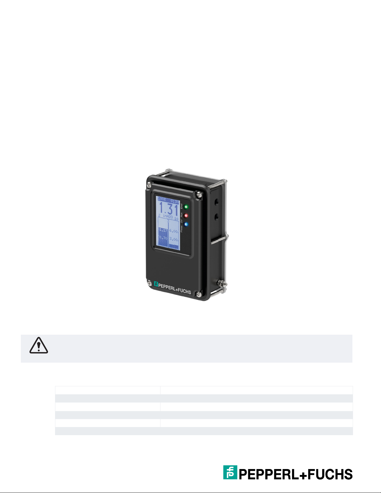
4.1 Control Unit
The 7500 control unit is a control device for Type Z & Ex pz purge systems and is suitable for purge time
and pressure monitoring in Class I or II, Division 2, Zone 2 or 22. It controls the volume of purge gas flowing
into the explosion-protected control cabinet, and it maintains and monitors an overpressure relative to the
ambient air when purging is complete.
The 7500 control unit can be ordered as a stand-alone unit for panel mounting to your enclosure or mounted
to a panel with the 7500-MAN-MV-01 valve in a configuration.
Control Unit Components
7500 control unit
Mounting bracket, gasket, and screws for enclosure mounting
Manual
Warning!
The conduit hub extension, 7500-HUB-AA-01, can only be mounted once to the 7500 control unit. If
removed, it cannot be reinstalled. A new conduit unit must be purchased.
nent
4.1.1 Technical Data—Control Unit
General specifications
Equipment architecture max. enclosure size 450 ft3 (12.7 m3)
Operating mode fully automatic (FA)
Series 7500
Hazardous environment gas or dust
Supply
10
Page 11

7500 Series Manual
Rated voltage U
r
20 ... 30 V DC at 0.1 A
90 ... 250 V AC, 50 ... 60 Hz at 0.04 A without solenoid valve
Supply voltage can be line-to-line or line-to-neutral, single phase
OVC II
Power consumption max. 2.7 W / 7.3 VA without valve
Accuracy pressure readings: ± 2 %
timers: ± 5 %
Electrical specifi cations
Connection screw terminals—see manual for specifi cations on wire size and
torque values
Output
Output I
Connection K1, terminals, 1 x NO
Output type enclosure power contacts
Contact loading 5 A at 250 V AC , 5 A at 30 V DC, relays must be externally fused
inrush current: 50 A
Output II
Connection K2, terminals, 1 x NO
Output type alarm and control contacts
Contact loading 5 A at 250 V AC , 5 A at 30 V DC, relays must be externally fused
inrush current: 50 A
Output III
Connection K3, terminals, L1 powered contact
Output type solenoid manifold, contact
Inrush current 5 A
Contact loading 0.5 A at 250 V AC , 0.5 A at 30 V DC, relays must be externally fused
Indicators/settings
LED indicator K1: Green - Contact K1 is energized (enclosure contacts)
K2: Amber - Contact K2 is energized (alarm/control contacts)
P/SV: Blue - Safe pressure P1 (minimum enclosure pressure)
P/SV: Amber - Solenoid manifold is energized (purging/pressure
compensation)
Pneumatic parameters
Protective gas supply compressed air or inert gas, 5 m fi lter, free from oil
Pressure requirement supply pressure: 20 ... 120 psig (1.4 ... 8.2 bar)
Safe pressure 0.38 in wc (0.95 mbar) for gas
0.8 in wc (2.0 mbar) for dust
Enclosure pressure 0 ... 10 in wc (0 ... 25 mbar)
Directive conformity
Electromagnetic compatibility
Directive 2014/30/EU EN 61326-1, FCC CFR 47, part 15, subpart B: 2017, Class A
ICES-003, Issue 6:2016, Class A ITE
RoHS
Directive 2011/65/EU (RoHS) EN 50581:2012
Conformity
Ambient conditions
Ambient temperature -40 ... 70 °C (-40 ... 158 °F) at T4 / T80°C
-40 ... 65 °C (-40 ... 149 °F) at T5 / T75°C
-40 ... 50 °C (-40 ... 122 °F) at T6 / T60°C
Storage temperature -40 ... 80 °C (-40 ... 176 °F)
Altitude max. 2000 m
Relative humidity 5 ... 90 %, non-condensing
Vibration resistance 5 ... 100 Hz , 1 g, 12 m/s
2
, all axes
Impact resistance 30 g, 11 ms, all axes
11
Page 12

7500 Series Manual
Mechanical specifi cations
Connection type electrical: 2 x 1/2 inch NPTF (open from factory)
Degree of protection Type 4X, IP66
Material lens: Makrolon
Mass 710 g (1 lb 10 oz)
Dimensions 150 x 100 x 50 mm (5.9 x 4 x 2 in)
Data for application in connection
with hazardous areas
Certifi cate
Marking
Directive conformity
Directive 2014/34/EU IEC/EN 60079-0, IEC/EN 60079-2, IEC/EN 60079-7,
International approvals
UL approval
cULus Class I, Division 2, Groups A, B, C, D T4 (-40 °C Ta 70 °C)
IECEx approval Ex ec nC [pzc] IIC T6...T4 Gc
General information
Supplementary information Type Examination Certifi cate, Declaration of Conformity, and
1 x M12 opening (plugged from factory)
pneumatic: high-pressure port - 1/8 in NPTF, low-pressure port - 1/8
in NPTF
No ratings for mounting to enclosure for 7500-MTD-BX...
®
GP-V polycarbonate
screws: AISI 316 (1.4401), 304, or 18-8 stainless steel
housing: A380, A356, or 6061-T6 aluminum
mounting gasket: Bisco® HT-800 medium cellular silicone
mounting tabs: SAE 304 stainless steel
M12 plug: 6061-T6 aluminum
II 3 G Ex ec nC [pzc] IIC T6...T4 Gc
II 3 D Ex tc [pzc] IIIC T60 °C ... T80 °C Dc
IEC/EN 60079-15, IEC/EN 60079-31
Supplements: EN 61010-1:2010
Class I, Division 2, Groups A, B, C, D T5 (-40 °C Ta 65 °C)
Class I, Division 2, Groups A, B, C, D, T6 (-40 °C Ta 50 °C)
Class II, Division 2, Groups F, G T4 (-40 °C Ta 70 °C)
Class II, Division 2, Groups F, G T5 (-40 °C Ta 65 °C)
Class II, Division 2, Groups F, G T6 (-40 °C Ta 50 °C)
Ex tc [pzc] IIIC T60 °C ... T80 °C Dc
instructions have to be observed where applicable. For information
see www.pepperl-fuchs.com.
4.1.2 Terminal Connection Data
Conductor cross section solid max. 0.2 mm²
Conductor cross section solid max. 6 mm²
Conductor cross section fl exible min. 0.2 mm²
Conductor cross section fl exible max. 4 mm²
Conductor cross section fl exible, with ferrule without plastic sleeve min. 0.25 mm²
Conductor cross section fl exible, with ferrule without plastic sleeve max. 4 mm²
Conductor cross section fl exible, with ferrule with plastic sleeve min. 0.25 mm²
Conductor cross section fl exible, with ferrule with plastic sleeve max. 4 mm²
Conductor cross section AWG min. 24
Conductor cross section AWG max. 10
12
Page 13
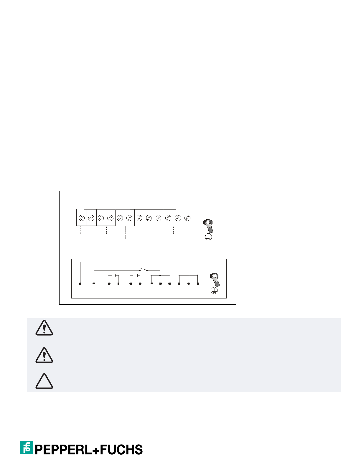
4.1.3 Wiring Requirements and Electrical Connections
Alarm/
Encl
Encl
Valve
L/L1/+
N/L 2/-N/L 2/-
Terminal Block Connections
Te rm in a l Bl o ck
L /L1/+ SV1 Alarm/Encl
K2
En c l
K1
N /L 2/-N /L2/-
Protective
earth
Wiring Requirements
1. All applicable local and national wiring codes must be followed when wiring the system.
See IEC 60079-14 for more information.
2. The power supply to this device shall have a separate disconnect. If placed in the hazardous area, it shall
be rated for the area in which it is being installed. Placing the disconnect into the purged enclosure is not
a "safe" area since power needs to be applied to the control unit before the purge cycle is complete.
3. The protective earth wire must be the same size as largest wire used to bring power into the enclosure.
Terminate using a ring lug that is properly crimped at the protective earth stud in the bottom of the
enclosure. The protective earth terminal torque is 12 in lb (1.36 Nm).
4. All wire shall be copper only, rated at a minimum of 80 °C.
5. The wire strip length into the fixed terminal block is 8 mm.
6. The terminal torque is 0.5 Nm to 0.6 Nm.
7. There shall be only one wire per terminal.
8. It is recommended to leave a bit of extra wire loop in the housing.
Electrical Connections
7500 Series Manual
Warning!
When connecting line-to-line power and K1 and K2 are used to switch the power, the alarm function is not
available. For more information, see chapter 6.11.
Warning!
When powering the system line-to-line, both lines are present if K3 is used. In this event, both sides of the
relay contacts must be fused.
Caution!
Use ferrules with all stranded wire types.
13
Page 14
7500 Series Manual
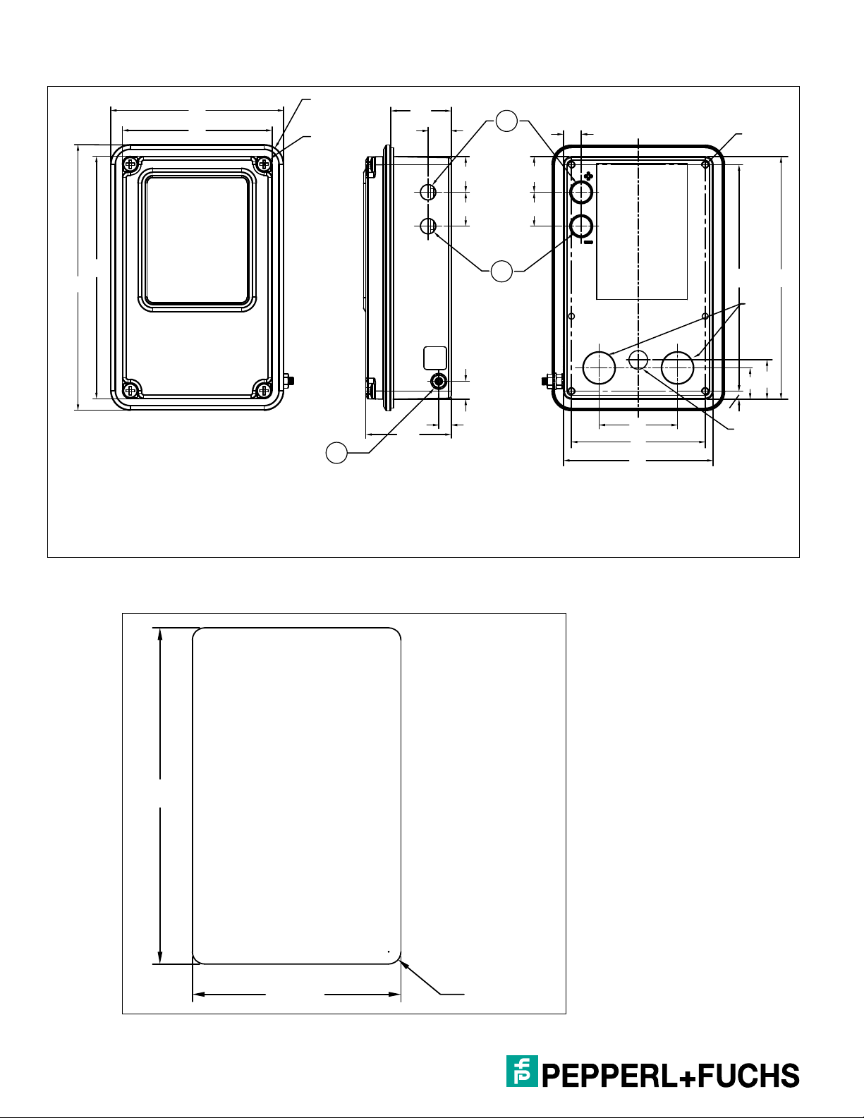
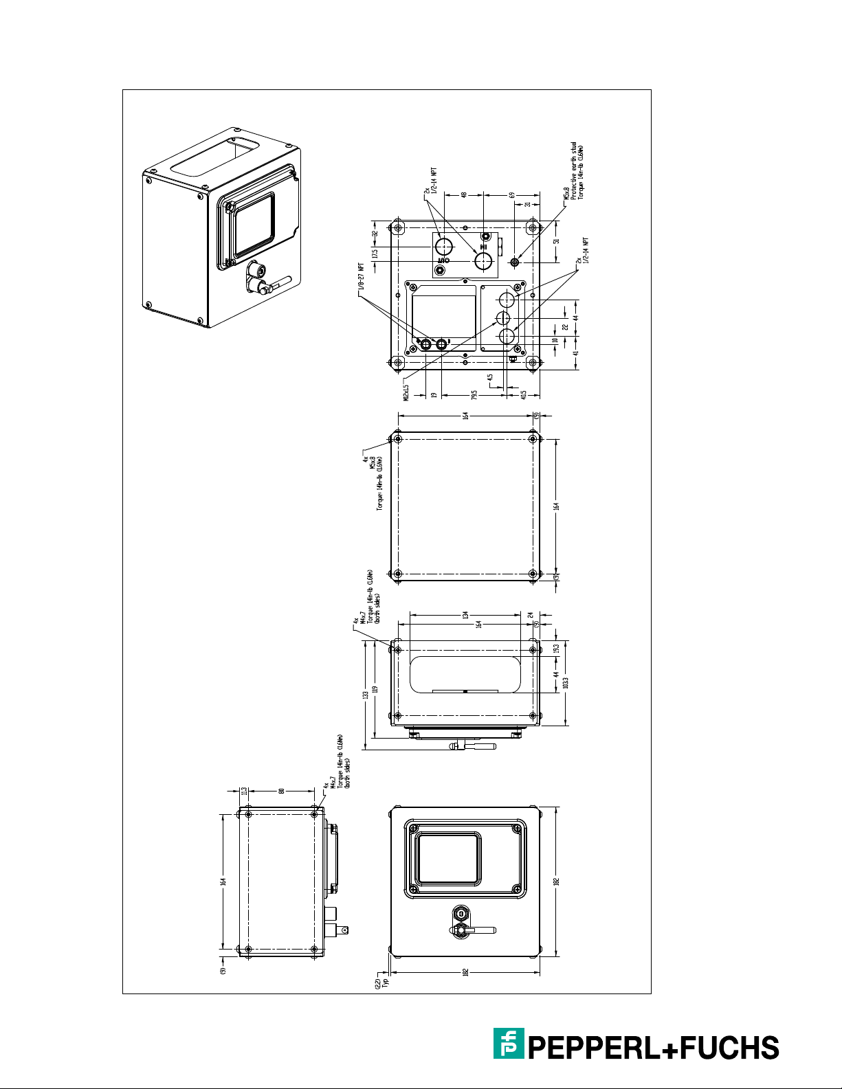
4.1.4 Dimensions—Control Unit
149
4 x
R11
4 x
R4.5
48
3
136
97
84
1. High-pressure port 1/8-27 NPT
2. Low-pressure port 1/8-27 NPT
3. Protective earth stud, torque 12 in lb (1.35 Nm)
34
13
20
19 19
10
7
1
2
20
10
44
75
84
127
4.5
M12 x 1.5
4 x
M4 x .7
1/2-14
NPT
17.5
136
22
4.1.5 Panel Cut-Out Dimensions
137 ± 0.5
85 ± 0.5 4 x R5 ± 1
14
Page 15
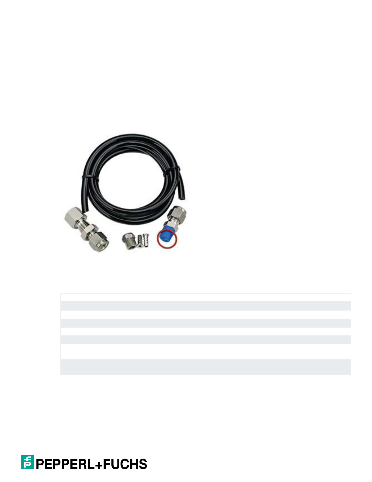
4.1.6 Pressure Kit
The included pressure kit contains the following components:
Bulkhead fitting
O-ring
Tubing
Tubing inserts
Straight connector
Sintered element for bulkhead fitting
7500 Series Manual
4.1.7 Torque Requirements
Hardware Torque
Main lid 12 in lb (1.36 Nm).
M4 screws for mounting bracket 12 in lb (1.36Nm).
Screws for mounting HUB 12 in lb (1.36 Nm).
M12 plug 15 in lb (1.70 Nm).
Panel mount bracket hardware Tighten evenly to a uniform gasket thickness of 1.3 mm to 1.7 mm
Set screws to mount control unit in panel Tighten until control unit is touching metal-to-metal around all
Manifold mounting hardware Tighten hardware until gasket is compressed 0.64 mm to 0.96 mm
edges
(use washers provided)
15
Page 16
7500 Series Manual
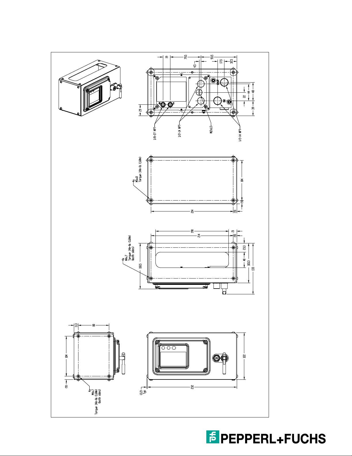
4.1.8 Dimensions—7500-MTD-* External/Panel Mount Systems
7500-MTD-BXRW-01 Rectangular External Mount with Control Unit and Manifold
16
Page 17

7500 Series Manual
7500-MTD-PMRW-01 Rectangular Panel Mount with Control Unit and Manifold
17
Page 18
7500 Series Manual
7500-MTD-BXSW-01 Square External Mount with Control Unit and Manifold
18
Page 19

7500-MTD-PMSW-01 Square Panel Mount with Control Unit and Manifold
7500 Series Manual
19
Page 20

7500 Series Manual
4.1.9 External/Panel Mounting Illustration
20
Page 21

4.2 EPV-7500 Vents
EPV-7500 vents work with the 7500 control unit and manifold to provide a functional, certifiable purge and
pressurization system for enclosures. As required by all pressurized enclosure systems, the EPV-7500 vent
functions as a pressure relief device and allows the purge gas to exit the enclosure, yet provides a seal
when the enclosure is pressurized and operating. The vent also has a spark arrestor, which is required for
hazardous areas.
EPV-7500-...-01/02/03 EPV-7500-PY-04
7500 Series Manual
EPV-7500 Components
EPV-7500 vent with spark arrestor
Sealing washer and nut for internal or external mounting
Hex key for removing, attaching, and rotating the vent cap
4.2.1 Technical Data—EPV-7500 Vents
General specifications
Equipment architecture max. enclosure size 450 ft3 (12.7 m3)
Series 7500
Hazardous environment gas or dust
Pneumatic parameters
Protective gas supply compressed air or inert gas, 5 m fi lter, free from oil
Maximum pressure depends on the integrity of the enclosure (strength)
Purge fl ow rate See tables
Flow rate for leakage compensation EPV-7500....-01:
Breaking pressure EPV-7500....-01: 0.8 in wc (2.0 mbar)
approx. 25 scfh (707 l/hr) at 0.25 in wc (0.63 mbar)
approx. 65 scfh (1838 l/hr) at 0.75 in wc (1.9 mbar)
EPV-7500....-02:
approx. 20 scfh (565 l/hr) at 0.25 in wc (0.63 mbar)
approx. 48 scfh (1357 l/hr) at 0.75 in wc (1.9 mbar)
EPV-7500....-03 and EPV-7500-PY-04:
approx. 15 scfh (424 l/hr) at 0.25 in wc (0.63 mbar)
approx. 25 scfh (707 l/hr) @ 0.75 in wc (1.9 mbar)
EPV-7500-...-02: 1.4 in wc (3.5 mbar)
EPV-7500-...-03: 1.5 in wc (3.8 mbar)
EPV-7500-PY-04: 1.4 in wc (3.5 mbar)
21
Page 22

7500 Series Manual
Directive conformity
Electromagnetic compatibility
Directive 2014/30/EU EN 61326-1, FCC CFR 47, part 15, subpart B: 2017, Class A
RoHS
Directive 2011/65/EU (RoHS) EN 50581:2012
Conformity
Degree of protection Directive conformity: see Declaration of Conformity
Ambient conditions
Ambient temperature -40 ... 70 °C (-40 ... 158 °F) (AA and SS versions)
Storage temperature -40 ... 80 °C (-40 ... 176 °F) (AA and SS versions)
Relative humidity 5 ... 90 %, non-condensing
Vibration resistance 5 ... 100 Hz , 1 g, 12 m/s
Impact resistance 30 g, 11 ms, all axes
Mechanical specifi cations
Degree of protection EPV-7500....-01/02: mounting only Type 4X
Material EPV-7500-AA...: body and cap 6061T6 aluminum
Housing EPV-7500-AA... body and cap 6061T6 aluminum body and cap:
Spark arrestor 304 stainless steel
Installation - any orientation to enclosure
Mass approx. 1005 g (2.2 lb)
Dimensions See dimensions in chapter 4.2.3
Mounting EPV-7500-...-01/02/03: mounting hole 1.5 in NPT knockout (50.8
Data for application in connection
with hazardous areas
Certifi cate
Marking ATEX: part of 18ATEX2025X
International approvals
cULus Part of the cULus classifi ed 7500 purge system
ICEx approval Part of IECEx UL 18.0022X
ICES-003, Issue 6:2016, Class A ITE
-20 ... 60 °C (-4 ... 140 °F) (PY versions)
-20 ... 60 °C (-4 ... 140 °F) (PY versions)
2
, all axes
EPV-7500....-03: Mounting and unit Type 4X
EPV-7500-SS...: body: 6061T6 aluminum, cap: AISI 316 (1.4401)
stainless steel
EPV-7500-PY...: body and cap: polyoxymethylene (POM)
Spark arrestor: AISI 316L (1.4404) stainless steel
6061T6 aluminum
EPV-7500-SS... body: 6061T6 aluminum, cap: AISI 316L (1.4404)
stainless steel
EPV-7500-PY... body and cap: polyoxymethylene (POM)
- not gravity dependent
- internal and external mounting possible
mm) hole sealing nut (provided)
EPV-7500-PY-04: mounting hole 37 mm with sealing nut (provided)
22
Page 23

4.2.2 Flow Rate Curves
The enclosure pressure vs. flow rate curves below represent the EPV-7500....-01, 02, 03, and 04 vents. This
corresponds to the enclosure pressure and is independent of the valve used, provided the valve can deliver
the flow rate that is required.
The vent flow tables represent the flow rate and enclosure pressure for each vent with a safety margin
attached to the values. Enclosure pressure may be less than the tables below for actual measured value.
The values below do not take into account leakage from the enclosure; they represent a perfectly sealed
enclosure. In most applications, the enclosure will have leakage, which will require higher flow rate into
the enclosure to achieve the correct reading. This extra flow will depend on the leakage throughout the
enclosure.
There is no restriction of enclosure size for each vent, but leakage rate, flow rate, enclosure pressure, and
the 7500 maximum purge time of 254:59 should be considered when applying these vents.
The EPV-7500-…-01 is usually used on large enclosures because it has a higher flow rate and lower back
pressure within the enclosure than the other versions. This can reduce the purging time while keeping the
enclosure pressure low, which is important for a large enclosure. However, this vent leaks more pressure
through its flow control mechanism.
The EPV-7500-…-02 provides a better seal at the vent than the EPV-7500-…-01. The flow rate for purging is
less for the same enclosure pressure of the ‘-01’ version.
7500 Series Manual
The EPV-7500-…03 provides the best seal for pressurization and should be selected for a smaller enclosure,
bottled air, or inert gas sources, and for increased conservation of the protective gas source. The flow rate is
less than the ‘-01’ and ‘-02’ versions but provides very low leakage.
The EPV-7500-PY-04 is similar to the EPV-7500-…03 vent and is used in the same applications, but it
is made out of polyoxymethylene and is lower in cost. The flow rate and enclosure pressure are slightly
different. See the tables below for exact values.
EPV-75000-...-01 Vent Flow vs. Enclosure Pressure
ft3/m Inches of water l/m mbar
5 1.41 141 3.49
7 1.57 198 3.89
10 1.77 282 4.39
12 1.93 339 4.78
15 2.23 424 5.53
17 2.43 480 6.02
20 2.66 565 6.59
25 3.08 707 7.63
30 3.63 848 9
35 4.28 990 10.62
23
Page 24

7500 Series Manual
EPV-7500-...-02 Vent Flow vs. Enclosure Pressure
ft3/m Inches of water l/m mbar
5 2.28 141 5.7
7 2.48 198 6.2
10 2.78 282 6.95
12 2.98 339 7.45
15 3.28 424 8.2
17 3.48 480 8.7
20 3.78 565 9.45
25 4.38 707 10.95
30 4.88 848 12.2
35 5.38 990 13.45
EPV-7500-...-03 Vent Flow vs. Enclosure Pressure
ft3/m Inches of water l/m mbar
4 2.13 113 5.32
6 2.33 170 5.82
8 2.53 226 6.32
10 2.83 282 7.07
12 3.63 339 9.07
14 4.78 396 11.95
16 6.23 452 15.57
EPV-7500-...-04 Vent Flow vs. Enclosure Pressure
ft3/m Inches of water l/m mbar
3 2.63 85 6.53
4 2.88 113 7.15
5 3.23 141 8.02
6 3.53 170 8.77
7 3.93 198 9.76
8 4.33 226 10.76
9 4.73 254 11.75
10 5.13 283 12.75
11 5.63 311 13.99
12 6.23 339 15.48
13 6.93 368 17.22
14 7.83 396 19.45
24
Page 25

4.2.3 Dimensions—EPV-7500 Vents
EPV-7500-...-01/02/03
1 1/2 NPS thread
(3) Hex key 0.050" (included)
7500 Series Manual
57.2
57.2
EPV-7500-PY-04
55.0 mm (2.15")
28.0 mm (1.10")
127
23.4
Exhaust port Inlet port
49.5
73.2
98.5
41.0 mm (1.60")
30.0 mm (1.20")
70.0 mm (2.75")
111.0 mm (4.35")
9.0 mm (0.35")
41.0 mm (1.60")
25.0 mm (1.00")
28.0 mm (1.10")
55.0 mm (2.15")
57.0 mm (2.25")
25
Page 26

7500 Series Manual
4.3 7500-MAN-MV-01 Manual Manifold
The 7500-MAN-MV-01 combines in one device a ball valve for purging and a needle valve for pressurizing
an enclosure. The ball valve has a handle for easy actuation. To provide security and prevent tampering, the
needle valve requires a slot-head screwdriver to set the enclosure pressure.
Note!
The 7500-MAN-MV-01 manifold can be used with 7500 series or 5500 series purge and pressurization
systems.
4.3.1 Technical Data—7500-MAN-MV-01 Manifold
General specifications
Equipment architecture max. enclosure size 450 ft3 (12.7 m3)
Series 7500
Hazardous environment gas or dust
Pneumatic parameters
Protective gas supply compressed air or inert gas, 5 m fi lter, free from oil
Pressure requirement 10 ... 120 psig (0.7 ... 8.2 bar)
Purge fl ow rate pressurization valve : Cv (fl ow coe cient) = 0.4
purging valve : Cv (fl ow coe cient) = 1.4
Connections inlet/outlet : 1/2 inch NPTF
Ambient conditions
Ambient temperature -40 ... 70 °C (-40 ... 158 °F)
Storage temperature -40 ... 80 °C (-40 ... 158 °F)
Mechanical specifi cations
Degree of protection Type 4X
Material Gasket material : Bisco® HT-800 medium cellular
Mass < 1.8 kg (4 lb)
Dimensions see dimensions in chapter 4.3.2
26
Page 27

4.3.2 Dimensions—7500-MAN-MV-01 Manifold
7500 Series Manual
55
2 x
1/2-14 NPT
56
48
14
2 x
5.5 ø thru-hole
41.5
17.5
17.5
4.5
9
Ball valve
closed
55
18.25
32.5 40
20
17.5
Ball valve
open
35
42.5
17
80
Needle valve
5
27
Page 28

7500 Series Manual
4.4 Automatic Manifolds
Pepperl+Fuchs 5500 series automatic manifolds can be used with the 7500 system because the area
classification is the same for both systems. The 7500 system is certified with the control unit and the EPV7500 vents and does not include the manifolds. The 5500 manifolds have their own certification from the
manufacturers.
Note!
Different manifolds are available for different certification requirements.
5500-MAN…. manifold valves include a solenoid valve for purging and a needle valve for pressurization in
one manifold design. When the valve is energized, the solenoid valve is open and allows a high flow rate
of protective gas into the enclosure. The amount of flow is controlled by the regulated pressure supply of
the protective gas to the manifold. When the valve is de-energized, the flow is through the internal needle
valve and is adjustable with the included hex key (for CDUL valve) or slot-head screwdriver (EX01 and
CD01 valves). The solenoid valve is used for purging and leakage compensation, with signals from the
7500 control unit that will have these set points set up by the user.
Mounting hardware includes 3/8 inch tube compression fittings mounted on the manifold for input and
output flow, 3/8 inch tube compression bulkhead fitting for getting flow into the enclosure, and sealing
washers that are certified by UL with bolts to mount the manifold to the enclosure.
Also included is 1 meter of 3/8 inch poly tubing with 3/8 inch poly tube stiffener inserts that allow users to
connect plastic tubing to compression fittings without collapsing the tubing. Stainless steel tubing can be
used with existing fittings.
For NEC, ATEX, and IECEx applications, see the type code for the correct model. The 5500 valve system
works with the 5500 and 7500 control unit as well as EPV-5500 and EPV-7500 vents. The 7500 control
system is certified by UL for Class/Division installation.
Users can also use their own pneumatic system or the 7500-MAN-MV-01 manual manifold. These valves
are not part of the evaluation of the certification of the 7500 control unit and EPV-7500... vent.
1 Solenoid coil for purging
2 1/8 inch hex key adjustment for pressurization (included)
28
Page 29

7500 Series Manual
Tubing kit included mounting hardware included
5500 manifolds include the solenoid and manual needle valve
3/8 inch compression ferrule fittings for inlet and outlet protective gas source
3/8 inch compression ferrule bulkhead fitting that attaches to enclosure—for protective gas to inside
enclosure
3/8 inch poly tubing, length: 2 m
Inserts for poly tubing to ferrule fitting connection. If stainless steel tubing is used, inserts are not
required.
Hex key for pressurization valve included with 5500-MAN-CDUL version
Note!
When ordering, note the supply voltage of the 7500 control unit. Order the manifold valves accordingly.
Voltages are 24 V DC, 120 V AC, and 220 V AC. 5500 MAN-CDUL manifold valves are only available with
60 Hz operation.
4.4.1 Technical Data—5500 Manifolds
General specifications
Operation mode For automatic purging
Series 5500 and 7500
Hazardous environment gas or dust
Supply
Rated power equipment 5500-MAN-CDUL
24 V DC 5.6 W
120 V AC 7.2 VA, 60 Hz
230 V AC 7.2 VA, 60 Hz
Rated power equipment 5500-MAN-CD01
24 V DC 4.6 W
120 V AC 6.8 VA, 60 Hz
230 V AC 6.8 VA, 60 Hz
Rated power equipment 5500-MAN-EX01
24 V DC 2.6 W
120 V AC 3.1 VA, 50 ... 60 Hz
230 V AC 3.0 VA, 50 ... 60 Hz
Voltage tolerance ±10 %
Fuse rating on 5500 control unit
DC voltage 500 mA
AC voltage 80 mA
29
Page 30

7500 Series Manual
Pneumatic parameters 5500-MAN-CDUL (only 60 Hz for AC version)
Protective gas supply 5 m fi ltered air or inert gas
Pressure requirement 20 psi (1.4 bar) to 120 psi (8.2 bar)
Purge fl ow rate (solenoid valves) Cv (fl ow coe cient) = 1.4
Pressurization fl ow (needle valve) Cv (fl ow coe cient) = 0.24
Pneumatic parameters 5500-MAN-CD01
Protective gas supply 5 m fi ltered air or inert gas
Pressure requirement 20 psi (1.4 bar) to 120 psi (8.2 bar)
Purge fl ow rate (solenoid valves) Cv (fl ow coe cient) = 1.4
Pressurization fl ow (needle valve) Cv (fl ow coe cient) = 0.24
Pneumatic parameters 5500-MAN-EX01
Protective gas supply 5 m fi ltered air or inert gas
Pressure requirement 25 psi (1.7 bar) to 115 psi (8.0 bar)
Purge fl ow rate (solenoid valves) Cv (fl ow coe cient) = 1.4
Pressurization fl ow (needle valve) Cv (fl ow coe cient) = 0.24
Mechanical specifi cations
Degree of protection (connector) Type 7 and 9
Mass 2.8 lb (1250 g)
Dimensions See dimension drawings
Material
Housing Anodized aluminum
3/8 inch compression fi ttings AISI 316L (1.4404) stainless steel
Pressure ports 3/8 inch NPTF
Bulkhead fi tting AISI 316L (1.4404) stainless steel
Mounting bolts ¼-20, 316 stainless steel
Sealing washers
Pneumatic connection type Pneumatic
Input port 3/8 inch tube compression fi tting
Output port 3/8 inch tube compression fi tting
Electrical connection
5500-MAN-CD 1/2 inch NPTF thread connection with 24 inch (0.61 m) fl ying leads
5500-MAN-EX01 3 m cable
30
Warning!
Incoming power must be fused. If power is line-to-line, both must be fused. See chapter 4.1.3 for more
information.
Page 31

4.4.2 Dimensions—5500 Manifolds
5500-MAN-CDUL
27
32
118
30
70.7
7500 Series Manual
95.3
50.8
31.8
5500-MAN-EX01
41.4
1/2"-14 NPT
45.8
ø6.5 (4x)
24.1
14.6
61.5
12.7
82.3
50.373.2
3/8" NPT (2x)
7.1
69
81.4
38.1 22.2
12.7 22.2
22.2
1/4-20UNC
9.5 (4x)
38.1
38.1 14.8
1/4-20UNC
8 (4x)
10.7
45.2
30
72.2
53.3
75
27
23
73
23
73
31
Page 32

7500 Series Manual
5500-MAN-CD01
24.1
14.6
3/8" NPT (2x)
61.5
38.1 22.2
56.6
12.7 22.2
22.2
1/4-20UNC
0.375 (4x)
38
38.1 14.8
1/4-20UNC
9.5 (4x)
50.5
10.9
23
30
76.2
53.3
73
73
32
Page 33

5 Installation and Operation
The 7500 series control unit, vent, and manifold can be universally mounted to the customer enclosure. The
7500-01-AA-STD-UNV-PNO is panel-mounted to the enclosure. An included bracket provides a Type 4X /
IPX6 mounting. The7500-MTD-PM... includes the 7500-01... control unit and 7500-MAN-MV-01 mounted
onto a flat panel that is then panel-mounted to the enclosure with the included bracket and gasket for a Type
4X / IPX6 mounting. The 7500-MTD-BX... includes the 7500-01.. control unit and 7500-MAN-MV-01 mounted
onto an enclosure that can then mount externally to the main enclosure. The EPV-7500 vent can be externally
or internally mounted with just the cap showing for exhaust of pressure.
The 7500 system is designed to allow the enclosure to be located in Zone 2 or 22, Class I or II, Division 2
hazardous locations to operate safely by first making them safe internally. This is done either by purging out
the hazardous gas or manually cleaning out the dust hazard and then pressurizing the enclosure so that the
internal pressure prevents the hazardous atmosphere from entering. The 7500 control unit has a differential
pressure sensor within the unit that is pneumatically connected to the protective enclosure to provide
pressure for evaluation of the enclosure pressure and the flow through the enclosure during purging. If
pressure is lost, then power can remain on. An indication by an alarm or display has to notify the operator of
the condition. If the pressurized enclosure has been opened or a positive pressure has not been maintained,
then purging for hazardous gas or cleaning the enclosure out for dust atmospheres is required. The flow
measurement is evaluated by using the pressure in the enclosure and the known measured flow in the tables
through one of the vents selected.
5.1 For Gas Atmospheres
7500 Series Manual
If the protective enclosure has been opened or has been subjected to the hazardous atmosphere, purging
is required to flush out the hazardous gas that may be inside the protective enclosure. A protective gas is
introduced into the enclosure so that the pressure builds up and is exhausted through the enclosure. The
measurement of flow is achieved by the 7500 control unit pressure sensor measuring enclosure pressure
and using that pressure for the flow tables of the vent selected and enclosure size. Each vent has an
enclosure pressure vs. flow table for enclosure size that can be used to determine flow rate. This flow rate is
used to determine the purge time required to make the protective enclosure safe.
Note!
The flow rate tables generated for each vent are measured on a completely sealed enclosure with no
leakage from the enclosure. In real applications, there will be some leakage from the enclosure, which will
depend on the integrity of the seals and door windows, etc. As the enclosure pressure increases, the leakage
may also increase. Always plan on more flow from the protective gas to achieve enclosure pressure because
of the leakage.
After purging, the flow into the enclosure can be reduced so that just a small flow is used for leakage
compensation for pressurization of the enclosure.
5.2 For Dust Atmospheres
If the protective enclosure has been opened or has been subjected to the hazardous atmosphere, the
enclosure must be manually cleaned of all combustible dust, closed, and pressurized before supplying power
to the enclosure. For dust atmospheres, a higher pressure is required for pressurization and is reflected in the
pressure range within the 7500 programming setup.
5.3 For Gas and Dust Atmospheres
Danger!
EN and IEC 60079-2 standards do not state these requirements. Special consideration is needed, and a
proper certification body or authority having jurisdiction must be consulted.
33
Page 34

7500 Series Manual
5.4 Setting Up the System
1. Ensure that the system meets all electrical, mechanical, and pneumatic connections before operation.
Refer to this manual and standards for explanation of requirements.
2. Apply power to the 7500 series system.
3. Program the 7500 system using the user-interface display on the front of the 7500 control unit. See
chapter 6 for instructions.
Note!
This step is for initial setup of the 7500 system. This procedure can be skipped if the 7500 control unit has
been programmed for the application in which it will be used.
4. Make sure the control valve is closed before applying pressure to the system.
5. Use a regulated pressure source to the valve. Set the regulated pressure to 30 psig (2 bar) or lower. Do
not exceed the maximum pressure for the valve and tubing that is being used.
6. The pressure should be below 0.38 in wc (0.95 mbar). Slowly open the needle valve on the control valve
system so that the pressure is above P1. If one of the automatic manifolds, 5500-MAN, is being used,
the solenoid valve will energize either before P1 or after. This depends on the purge program being used.
See chapter 6.5.
7. Check the EPV vent to make sure air is coming out of it. If not, check for any obstructions or improper
installation
8. The system is ready to operate.
5.5 Operating the System
1. Follow the preceding instructions for setting up the system.
2. For Programs 1 through 4 (hazardous gas environments), purging is required.
a. Seal the pressurized enclosure.
b. Set enclosure pressure to a value above P1.
c. When using the 5500-MAN… manifod, the manifold valve is connected to the SV1 output. When the
enclosure pressure is greater than P1, SV1 energizes the solenoid valve for purging. When using the
7500-MAN... or other manual valves, initiate the purging valve.
d. Adjust the regulated pressure so that enclosure pressure is above P3 (purging starts).
e. For the 5500-MAN or 7500-MAN manifold, after purging, the needle valve can be re-adjusted to the
user’s desire, but it must be above P1 value.
3. For Program 5 (hazardous dust environment), purging is not required.
a. The inside of the enclosure must be cleaned of all combustible dust.
b. The enclosure is sealed.
c. Adjust the enclosure pressure above P1. The minimum for P1 is 0.8 in wc (2.0 mbar) for hazardous
dust environments.
4. If enclosure pressure is above P1, power to the enclosure will be energized.
5. If enclosure pressure drops below P1, power must be disconnected. If power is to remain on, an alarm
must be initiated and located near an operator.
6. To energize the pressurized enclosure again, repeat the above sequence.
Danger!
All 7500 pressurization systems require EPV-7500... vents for pressure relief.
34
Danger!
When accessing the user-interface display, the area must be free of hazardous gas and/or combustible dust.
The lid to the 7500 housing must be attached and propertly tightened for operation in a hazardous area.
Note!
At ambient temperatures below -20 °C, the display of the 7500 control unit may not be visible. However, the
unit and LED indicators will still function properly.
Page 35

6 Programming
Use the touch screen on the front of the 7500 control unit to program the system:
7500 Series Manual
Portrait View Landscape View
P ur gin g time: % co mple te / Time l eft
Enc losure P ress ure
X.XX in H O
0.35
P2
P1
X.XX
inH O
2
2
3
0.80
0.30
6.00
3.00
0:300%
10
Enclosure Pressure
0 to 10” w.c. range
P4
P3
CONTRAST
Bar Graph
Enclosure Pressure
To enter Purge Setup or Contrast
pres s and hold finger on the display
in position for 5 sec onds. To
SETUP
CONTRAST
enter Contrast push at location
shown
To en t er Pu rg e Setu p o r Co n trast
pres s and hold finger on the display
in position for 5 sec onds. To
enter Contrast push at location
shown
2
0.80
3.00 6.00
P2
P3
P1
P4
SETUP
P ur gin g time: % co mple te / Time l eft
0:300%
3
2
Pur ging Progr am
0 to 2” w.c. range
0 to 10” w.c. range
10
Bar Graph
Enc losure P ress ure
Program settings are saved on non-volatile memory within the CPU, and settings are unaffected by powerdown and reset function.Default values are stored and can be restored.
Note!
To save settings and exit setup mode, hold the set button to return to normal mode. Changes to settings take
effect immediately. Entering the incorrect password will exit setup mode.
Warning!
Do not change program settings in hazardous areas.
35
Page 36

7500 Series Manual
6.1 LED Indication
LED Color Description
K1 Green Contact K1 is energized
K2 Amber Contact K2 is energized
P/SV Blue/amber Blue: safe pressure
6.2 Default Settings
The following table shows all the possible parameters and their default values:
Display Description Default values
PASSWORD / SET Enter password to access
PURGE / PROGRAM Up to 5 programs to select 3
PURGE / TIME Time required for purging 00:30
ENCLOSUR / PRESS P1 Enclosure pressure P1 0.38 inch (gas), 0.8 in
ENCLOSUR / PRESS P2 Enclosure pressure P2 0.8 inch (2.0 mbar)
ENCLOSUR / PRESS P3 Enclosure pressure P3 2.5 inch (6.22 mbar)
ENCLOSUR / PRESS P4 Enclosure pressure P4 4.5 inch (11.20 mbar)
LEAKAGE / HYST Compensates for leakages 0.2 inch H20 (0.5 mbar)
PROGRAM / K2 Various parameters to acti-
SHUT-OFF / DELAY Delay in turning K1 o when
UNITS / M I M for metric units, I for im-
CHANGE / PASSWORD Change existing password
RESTORE DEFAULTS Factory restore
DISPLAY ROTATION Landscape or portrait Portrait
CYCLE POWER Power o then on O
Amber: valve on
0000
purge settings
(dust)
0.95 mbar (gas), 2.0 mbar
(dust)
K1*
vate K2 contacts
0 sec
P<P1
I
perial units
* Warning!
K1 is not an alarm output. See chapter 6.11 for programming details on what controls K2.
6.3 Contrast and Back light
Adjusting the Contrast
To adjust the contrast, push on the display in the area marked “contrast.” The up and down arrows adjust the
contrast level—up increases and down decreases.
LCD Back Light
The LCD back light is always on. It cannot be turned off or adjusted.
36
Page 37

6.4 Menu Structure
7500 Series Manual
Power On
SET
5 sec.
PASSWORD
PURGE
PROGRAM
Purge
Time
ENCLOSUR
PRESS P1
ENCLOSUR
PRESS P2
ENCLOSUR
PRESS P3
LEAKAGE
HYST
PROGRAM
K2
SHUT-OFF
DELAY
BYPASS
UNITS
MI
CHANGE
PASSWORD
RESTORE
DEFAULT
DISPLAY
ROTATION
At any time during
purge settings
SET
5 sec.
ENCLOSUR
PRESS P4
CYCLE
POWER
PASSWORD
ENCLOSUR
PRESS
37
Page 38

7500 Series Manual
6.5 Purge Programming Settings
There are 5 program selections for system operation. Programs 1 through 4 are for hazardous gas
environments and require purging. The fifth program is for hazardous dust environments that require cleaning
the enclosure, then pressurizing.
6.5.1 Program 1
Program 1 is used in hazardous gas atmospheres.
Pre-Purge
The purge valve (SV) is immediately energized regardless of enclosure pressure
If enclosure pressure goes above P4 during purging, SV will shut off but will energize when below P4.
Oscillation of SV may be noticed.
Setting the pressurization valve on the manifold must be done after purging, or the power to SV will have
to be interrupted to set this pressure. The solenoid valve on the manifold is immediately energized before
this pressure can be set.
The purge timer begins counting down when the enclosure pressure is greater than P3. Enclosure
pressure must remain greater than P3 to purge successfully. If the pressure drops below P3 at any
time, or for any length of time, the purge timer is reset and will not begin counting down until pressure is
greater than P3.
Operation Mode
After the purge timer counts down, the SV shuts off and K1 is energized.
If enclosure pressure drops below P2, the SV is energized and will stay energized for the value of HYST
(%, leakage compensation). If HYST is set to 0, leakage compensation is turned off.
If enclosure pressure drops below P1, K1 remains on and an alarm shall be implemented. K2 can be set
to P- or Alarm to indicate below safe or operating pressure.
If enclosure pressure goes above P4, K1 remains. If K2 is set up as Alarm, K2 will energize.
38
Page 39

Warning!
If K1 is used to energize power to the enclosure, K1 will remain energized if pressure is below P1 during
system operation. An alarm is required and must be located such that an operator will be notified of the
alarm.
6.5.2 Program 2
Program 2 is used in hazardous gas atmospheres.
Pre-Purge
The purge valve (SV) is energized when enclosure pressure is greater than P1.
If enclosure pressure goes above P4 during purging, the SV shuts off but will energize when below P4.
Oscillation of SV may be noticed.
Setting the pressurization valve on the manifold has to be done after purging, or the power to SV will
have to be interrupted to set this pressure. The solenoid valve is energized once enclosure pressure
is above P1. Adjusting the pressurization valve before the solenoid valve is energized will allow the
enclosure pressure to be above P1 when purging is completed. Fine adjustment of P1 can be achieved
after purging when the solenoid valve is off.
The purge timer begins counting down when enclosure pressure is greater than P3 and must remain
greater than P3 to purge successfully. If the pressure drops below P3 at any time, or for any length of
time during purging, the purge timer is reset and will not begin counting down until pressure is greater
than P3.
7500 Series Manual
Operation Mode
After the purge timer counts down, the SV shuts off and K1 is energized.
If enclosure pressure drops below P2, the SV is energized and will stay energized for the value of HYST
(%, leakage compensation). If HYST is set to 0, leakage compensation is turned off.
If enclosure pressure drops below P1, K1 remains on, and an alarm shall be implemented. K2 can be set
to P- or Alarm to indicate below safe or operating pressure.
If enclosure pressure goes above P4, K1 remains. If K2 is setup as Alarm, K2 will energize.
Warning!
If enclosure pressure is below P1 when K1 is used to provide power to the enclosure during operation, K1
will remain energized. An alarm is required and must be located such that an operator will be notified of the
alarm.
39
Page 40

7500 Series Manual
6.5.3 Program 3
Program 3 is used in hazardous gas atmospheres.
Pre-Purge
The purge valve (SV) is energized when enclosure pressure is greater than P1.
If enclosure pressure goes above P4 during purging, the SV will shut off but will energize when below P4.
Oscillation of SV may be noticed.
Setting the pressurization valve on the manifold has to be done after purging, or power to SV will have to
be interrupted to set this pressure. The solenoid valve is energized once enclosure pressure is above P1.
Adjusting the pressurization valve before the solenoid valve is energized allows the enclosure pressure to
be above P1 when purging is completed. Fine adjustment of P1 can be achieved after purging, when the
solenoid valve is off.
Operation Mode
After the purge timer counts down, SV shuts off and K1 is energized.
If enclosure pressure drops below P2, the SV is energized and will stay energized for the value of HYST
(%, leakage compensation). If HYST is set to 0, leakage compensation is turned off.
If enclosure pressure drops below P1, K1 turns off immediately or after the Shutdown delay timer times
out. K1 remains off until the enclosure goes through a successful purging.
If enclosure pressure goes above P4, K1 remains. If K2 is set up as Alarm, K2 will energize
6.5.4 Program 4
Program 4 is used in hazardous gas atmospheres.
Pre-Purge
The purge valve (SV) is immediately energized regardless of enclosure pressure.
If enclosure pressure goes above P4 during purging, the SV shuts off but will energize when below P4.
Oscillation of SV may be noticed.
Setting the pressurization valve on the manifold has to be done after purging, or power to SV will have to
be interrupted to set this pressure. The solenoid valve on the manifold is immediately energized before
this pressure can be set.
The purge timer begins counting down when enclosure pressure is greater than P3, and it has to remain
greater than P3 to purge successfully. If the pressure drops below P3 at any time, or for any length of
time during purging, the purge timer is reset and will not begin counting down until pressure is greater
than P3.
Warning!
If enclosure pressure is below P1 when K1 is used to provide power to the enclosure during operation, K1
will remain energized. An alarm is required and must be located such that an operator will be notified of the
alarm.
40
Page 41

Operation Mode
After the purge timer counts down, SV shuts off and K1 is energized.
If enclosure pressure drops below P3, the SV is energized and will stay energized for the value of HYST
(%, leakage compensation). If HYST is set to 0, leakage compensation is turned off. However, Program 4
is usually used when a continuous purging through the enclosure is required during operation mode.
If enclosure pressure drops below P1, K1 remains on and an alarm will sound. K2 can be set to P- or
Alarm to indicate below safe or operating pressure.
If enclosure pressure goes above P4, K1 remains. If K2 is setup as Alarm, K2 will energize.
6.5.5 Program 5
Program 5 is used in combustible dust atmospheres.
Pre-Purge
The purge valve (SV) does not come on during this operation. In a dust atmosphere, purging is not
required. Instead, the enclosure must be cleaned of all combustible dust and then pressurized.
The menu screen will show "CLEAN ENCLOSURE." The enclosure should be cleaned and then
pressurized before pressing the SET button.
The enclosure pressure has to be above P1 (minimum 0.8 in wc (1.99 mbar) for dust atmospheres)
for the SET button to work.
7500 Series Manual
Operation Mode
After cleaning out and pressurizing the enclosure, the menu shows "CLEAN ENCLOSURE." To see the
enclosure pressure, press the Down or Up button. Pressing the SET button will energize K1.
If enclosure pressure drops below P2, the SV is energized and will stay energized for the value of HYST
(%, leakage compensation). If HYST is set to 0, leakage compensation is turned off. Compensation for
leakages is allowed in a dust atmosphere because the enclosure is safe at this point.
If enclosure pressure drops below P1, K1 remains on and an alarm will sound. K2 can be set to P- or
Alarm to indicate below safe or operating pressure.
If enclosure pressure goes above P4, K1 remains. If K2 is setup as Alarm, then K2 will energize.
Warning!
If enclosure pressure is below P1 when K1 is used to provide power to the enclosure during operation, K1
will remain energized. An alarm is required and must be located such that an operator will be notified of the
alarm.
41
Page 42

7500 Series Manual
6.5.6 Sequence of Events for All Programs
Program 1 2 3 4 5
Purging K1 SV K1 SV K1 SV K1 SV K1 SV
P<P1 o on o o o o o on o o
P1<P<P2 o on o on o on o on o o
P2<P<P3 o on o on o on o on o o
P3<P<P4 o on o on o on o on o o
P>P4 o o o o o o o o o o
After purging
P<P1 on on on on o o on o on o
P1<P<P2 on on on on on on on on on on
P2<P<P3 on o on o on o on on on o
P3<P<P4 on o
P<P4 on o on o on o on o on o
Note!
Shutdown timer and bypass affect the status of K1 and SV. See the explanation for each to determine effects
on K1 and SV.
on o on o on o on o
Clean activates
above P1
6.6 Purging Timer
MIN:SEC
000:00
To program the purging timer, proceed as follows:
Calculate the purging time using the formulas and examples in chapter 7.
Enter the purging time using the UP and DOWN buttons and SET.
To change purging time by 1 second increments, press the UP or DOWN button once.
To make purging time faster, hold down the button continuously. Purging time will advance faster, the
longer you hold the button down (in 5 seconds, 1 min, 5 min steps).
Maximum purge time is 254:59.
42
Page 43

6.7 Minimum Enclosure Pressure “P1”
In accordance with the applicable standards and tolerances on the 7500 pressure sensor, the minimum
operating pressures are as follows:
Gas environments: 0.38 in wc (0.95 mbar)
Dust environments: 0.8 in wc (1.99 mbar)
When enclosure pressure drops below P1 during operation mode, the power has to be interrupted. If not, an
alarm has to be generated to address the problem.
6.8 Alarm Pressure “P2”
If enclosure pressure drops below P2 during operation mode, the solenoid valve will energize until pressure
goes above P2+HYST. Therefore, leakage compensation has to be implemented.
If leakage compensation is not used, the P2 can sound an alarm to indicate that pressure is dropping.
P2 can be adjusted to above P1 and Below P3 values.
6.9 Purging Pressure “P3”
7500 Series Manual
The purging timer starts when enclosure pressure is above P3. If the pressure is above P3, purging will start
and finish uninterrupted. If the enclosure pressure is below P3, the purging timer will not start. If the pressure
drops below P3 during purging, the purging timer will immediately reset to its beginning time and will not start
timing down until pressure is above P3. P3 can be adjusted to above P2 and below P4 values.
6.10 Maximum Internal Pressure “P4”
If enclosure pressure is above P4, the display will read ‘MAX’ to indicate that maximum pressure has been
achieved. Regardless of the action of the solenoid valve (purging, leakage compensation), the solenoid valve
will de-energize and will not come on until enclosure pressure goes below P4. This action may cause the
solenoid valve to oscillate on and off. If this happens, it should be noted as a maximum pressure problem.
If K1 was on before P4 was reached, it will remain on after enclosure pressure is above P4. P4 is adjusted
above P3. Maximum setting is 9.99 in wc (24.86 mbar).
43
Page 44

7500 Series Manual
Leakage Compensation Hysteresis “HYST”
In operation mode, there may be excess leakage of pressure from the enclosure because a seal or gasket
has caused a drop in regulated line pressure (protective gas source). The leakage compensation option
allows the SV to turn on to compensate for these unintentional leakages. Depending on the purge program
being used, the SV will energize when below P2 and will de-energize when it is above P2 + hysteresis.
Note!
If leakage compensation is not required, set HYST to ‘0.’
Values for hysteresis HYST
Inches of wc mbar
00
0.2 0.5
0.4 1.0
0.6 1.5
0.8 2.0
1.0 2.5
1.2 3.0
1.4 3.5
1.6 4.0
1.8 4.5
2.0 5.0
Example
Units are in mbar, hysteresis = 15, then SV is on at P2 and turns off at P2 + 1.5
The HYST unit of measurement is the units being used.
If HYST = 1.5, then this is 1.5 mbar.
44
Page 45

6.11 Programming K2
The K2 contact output can be programmed for various settings that are chosen by the user.
For Type Z and Ex pz systems, power to the pressurized enclosure can remain on if pressure goes below the
minimum allowed pressure, but an audible and/or visual alarm must be generated to notify the operator of a
problem.
K2 can be used to generate the signal for the alarm when properly configured. Alarm function based on any
pressure point (P1 to P4 is not available when K2 is mapped to K1, purging or bypass. Additionally, the K2/
ALARM LED indication is not an alarm indication when K2 is mapped to these functions.
When K2 is mapped to a function that is not an alarm for loss of safe pressure, the power to the enclosure
must be removed, or an external method of alarming is required.
Users-Selectable Settings for K2
K1 Switches simultaneously with K1*
P1+ Switches on when pressure exceeds P1
P1- Switches o when pressure falls below P1
P2+ Switches on when pressure exceeds P2
P2- Switches o when pressure falls below P2
P3+ Switches on when pressure exceeds P3
P3- Switches o when pressure falls below P3
P4+ Switches on when pressure exceeds P4
P4- Switches o when pressure falls below P4
Purging Switches on when purge timer starts and shuts o at the end of
Bypass Switches on when the bypass function is activated
All Alarms Comes on when P1-, P4, Bypass
7500 Series Manual
purging
*This mode is intended for use when the system is controlling a line-to-line power source into the protected
enclosure and both power lines need to be switched.
45
Page 46

7500 Series Manual
46
Page 47

6.12 Shutdown Timer for K1
The shutdown timer is used in the operation mode and allows K1 to remain on for the duration of this setting
when enclosure pressure drops below the minimum setting of P1. If the pressure goes above P1 during the
countdown, the timer is reset. If the pressure remains below P1 for the duration of the countdown, K1 will
shut off.
The shutdown timer is effective only for Program 3, in which K1 de-energizes when enclosure pressure is
below P1. The other programs allow power to the enclosure to remain on when pressure is below P1, with an
alarm generated to the operator.
The default value is 0 seconds. The range is 0 to 300 seconds.
7500 Series Manual
47
Page 48

7500 Series Manual
6.13 Bypass
The Bypass mode allows power to the enclosure to be energized when the enclosure pressure is below the
minimum pressure P1. This can be useful in commissioning the enclosure or working on the enclosure when
it is open.
The Bypass option has two modes of operation to choose from.
Mode Description
N No Bypass is not enabled.
Y Yes Bypass is implemented using the purge settings menu. By select-
Danger!
Bypass should only be implemented when the area surrounding the pressurized enclosure is known to be
non-hazardous!
ing ‘Y’, the system will go into bypass and will turn on K1. In the
‘Y’ mode, K1 can be energized before the system goes through a
successful purge. This mode can be useful in commissioning the
enclosure during start up. This mode is on when it is selected and
the menu stays in the purge settings mode. If the user exits from
the purge settings mode, then the Y’ is automatically changed to
‘N’ and K1 will de-energize.
Bypass LED is on.
6.14 Units
The units can be changed from ‘M’ metric to ‘I’ imperial. This affects the pressure readings. "M" reads in
mbar, and "I" reads in inches of water column. The temperature settings are always in Celcius.
48
Page 49

6.15 Change Password
To change the existing password, use the UP and DOWN buttons for each digit.
Enter 4 digits.
To cancel without saving a new password, press RESET. The existing password will still be valid.
Note!
There is no confirmation of key strokes when changing the password. Note what the new password is when
changing it.
7500 Series Manual
49
Page 50

7500 Series Manual
7 Determining Purging Time
To make sure the enclosure is safe from the hazardous atmosphere, the inside of the enclosure has to be
free of the hazardous atmosphere and pressurized before the equipment inside can be powered.
The first step in this process is to get rid of the hazardous atmosphere within the enclosure.
For a dust atmosphere, the inside of the enclosure must be cleaned out and then pressurized. Because most
vents on a pressurized enclosure have a spark arrestor, purging is not the method used. The dust must be
cleaned out manually or with a vacuum that is rated for the area. Alternatively, it must be cleaned out in a
non-hazardous area.
For gas atmospheres, the enclosure is purged by introducing a flow of protective gas (compressed air, or
Inert gas) through the enclosure to make it safe. Depending on the standards that are being used to evaluate
the effectiveness of the purging operation, the volume of protective gas through the enclosure determines
the amount of time for purging. The exchange of protective gas is related to the volume of the enclosure, the
number of exchanges, and the flow rate through the enclosure.
Below is an equation for determining the purging time:
(number of volume exchange) x (volume of the enclosure) / flow rate = purging time
The number of volume exchange depends on the item being purged and the standard it is being evaluated:
Number of exchanged Class/Division (NFPA 496) Zone (60079-2)
4 X n/a
5 n/a X
10 (motors) X X
Example:
P3 = 2.6 inch H2O 6.5 mbar
Vent = EPV-7500-...-02
table for P3: EPV-7500-...-02,
see chapter 4.2.2
Enclosure volume = 10 ft3 282 liters
Flow Rate from P3 (see table) 11.3 scfm 320 liters/min
NEC (class/division) 4 volume exch. 4 volume exch.
Zone (ATEX, IECEx) 5 volume exch. 5 volume exch.
NFPA: 4 x 10 ft3 / 11.3 scfm = 3.6 min 4 x 282 liters / 320 l/min = 3.6 min
Zone: 5 x 10 ft³ / 11.3 scfm = 4.5 min 5 x 282 liters / 320 l/min = 4.5 min
Motors: 10 x 10 ft³ / 11.3 scfm = 8.9 min 10 x 282 liters / 320 l/min = 8.9 min
The 7500 control unit has a purge timer and is user-selectable through the menu.
The purge timer is activated when the enclosure pressure goes above P3. The pressure must always be
above P3 for the timer to continue until it counts down to 000:00. If the enclosure pressure drops below P3 for
any amount of time, then the timer is reset to its starting value and will not start counting down until pressure
is above P3.
The flow rate for P3 value can be found on the tables for vent flow in chapter 4.2.2. The flow rate for P3
depends on the EPV-7500 vent that is being used.
The more the enclosure leaks pressure, the higher the flow rate into the enclosure required to achieve the P3
threshold.
50
Page 51

8 User Parameter Setting Sheet
Display Description User Settings
PASSWORD / SET Password
PURGE / PROGRAM Program 1-5
PURGE / TIME Time required for purging
ENCLOSUR / PRESS P1 Shutdown pressure P1
ENCLOSUR / PRESS P2 Alarm/signal pressure P2
ENCLOSUR / PRESS P3 Purge pressure P3
ENCLOSUR / PRESS P4 Maximum pressure P4
LEAKAGE / HYST Leakage comp and hysteresis
PROGRAM / K2 K2 program
SHUT-OFF / DELAY Shutdown timer for K1
BYPASS / N Y Bypass
UNITS / M I M for metric, I for imperial units
CHANGE PASSWORD Change password
RESTORE DEFAULTS Factory restore
DISPLAY ROTATION Landscape or portrait
CYCLE POWER Cycle power
7500 Series Manual
51
Page 52

7500 Series Manual
9 Type Codes
7500 Control Unit
Standard control unit
7500-MTD-* Panel/External Mount System
EPV-7500 Vents
52
Page 53

7500-MAN-MV-01 Manifold
5500 series manifolds
7500 Series Manual
53
Page 54

7500 Series Manual
10 Certifications
10.1 Applied Standards
Note!
See the certificates and/or the Declaration of Conformity for details on specific editions of the below-listed
standards.
IECEx and ATEX:
IEC/EN 60079-0
IEC/EN 60079-2
IEC/EN 60079-7
IEC/EN 60079-15
IEC/EN 60079-31
10.2 Markings
Control Unit 7500-01-AA-STD-...
4S11
AVERTISSEMENT –
CL I/II, Div 2, Grp A-D, F-G T6...T4
AExecnC[pzc]IICT6...T4Gc
AExtc[pzc]IIICT60 C...T80 CDc
Ex ec nC [pzc] IIC T6...T4Gc
Ex tc [pzc] IIIC T60 C...T80 C Dc
UL E184741
Type4X /IP66
°°
°°
T60°C...
T60°C...
-40ºC Ta 70ºC≤≤
.
54
Page 55

Control Unit and Manual Manifold, 7500-MTD-...
7500 Series Manual
UL file E184741
4S11
-40ºC Ta 70ºC≤≤
EPV-7500 Vents
4S11
UL E184741
-40ºC Ta 70ºC≤≤
4S11
4S11
UL file E184741
Type4X
-40ºC Ta 70ºC≤≤
UL E184741
-40ºC Ta 70ºC≤≤
4S11
UL E184741
-20ºC Ta 60ºC≤≤
55
Page 56

7500 Series Manual
11 Maintenance and Repair
Do not remove the window from the 7500-01-... control unit. If the window is damaged or removed, the
control unit cannot be repaired. A new unit is required.
Do not remove the accessory conduit hub extension, 7500-HUB-AA-01, from the 7500-01-... control unit.
If the conduit hub is damaged or removed, the conduit hub cannot be reinstalled. A new conduit hub is
required. The conduit hub is an accessory and is not included with the 7500-01-... control unit.
The only special maintenance required on the 7500 system is cleaning of the pneumatic filters on the
overall installation, when used, and periodic function checks. This includes pressure readings within the
specifications contained in this manual. When checking pressure measurements of the 7500 control unit,
use calibrated equipment to determine the measurements, or contact a Pepperl+Fuchs representative or the
factory to send the device back for function verification.
Warning!
There are no user-serviceable portions of the 7500 system.
Warning!
When operating the 7500 system in conjunction with a hazardous area, do not modify the system. If there is
a defect, the product may need to be replaced. Repairs can only be performed by a Pepperl+Fuchs specialist
who is trained and authorized to repair the defect.
Warning!
When servicing, installing, and commissioning, the area must be free of all combustible material and/or
hazardous explosive gas. Only the terminal compartment of the control unit is accessible to users. Under no
circumstances shall the control unit or vent be dismantled or removed from the supplied enclosure, unless
instructed in this manual.
Contact Pepperl+Fuchs customer service for an RMA (return merchandise authorization).
12 Troubleshooting
Problem Possible Reason Solution
Purge cycle does not start No air to system Check air supply, make sure mini-
mum pressure is available.
Minimum pressure not high
enough
Control unit in dust mode Program 5 was used instead of
Check vent and enclosure seals,
check compensation valve setting.
programs 1-4. Select the proper
program.
13 Dismantling and Decommissioning
Abide by all local and any other code requirements for disposing of electronic equipment. When disposing of
any component of the 7500 system, VOID must be marked across all certification labels.
56
Page 57

7500 Series Manual
This page left blank intentionally.
57
Page 58

7500 Series Manual
58
This page left blank intentionally.
Page 59

7500 Series Manual
This page left blank intentionally.
59
Page 60

Pepperl+Fuc hs Qualit y
Download our latest policy here:
www.pepperl-fuchs.com/quality
www.pepperl-fuchs.com
Subject to modifi cations
Printed in USA
TDOCT-B1V3BENG 06/20
·
·
© Pepperl+Fuchs
 Loading...