

Page 1
ENA**TL-**IO**
Absolute Rotary Encoder
with IO-Link
Manual
Page 2

With regard to the supply of products, the current issue of the following document is applicable: The
General Terms of Delivery for Products and Services of the Electrical Industry, published by the Central
Association of the Electrical Industry (Zentralverband Elektrotechnik und Elektroindustrie (ZVEI) e.V.)
in its most recent version as well as the supplementary clause: "Expanded reservation of proprietorship"
Worldwide
Pepperl+Fuchs Group
Lilienthalstr. 200
68307 Mannheim
Germany
Phone: +49 621 776 - 0
E-mail: info@de.pepperl-fuchs.com
North American Headquarters
Pepperl+Fuchs Inc.
1600 Enterprise Parkway
Twinsburg, Ohio 44087
USA
Phone: +1 330 425-3555
E-mail: sales@us.pepperl-fuchs.com
Asia Headquarters
Pepperl+Fuchs Pte. Ltd.
P+F Building
18 Ayer Rajah Crescent
Singapore 139942
Phone: +65 6779-9091
E-mail: sales@sg.pepperl-fuchs.com
https://www.pepperl-fuchs.com
Page 3

ENA**TL-**IO**
Contents
1 Introduction................................................................................................................ 5
1.1 Content of this Document ............................................................................. 5
1.2 Target Group, Personnel ............................................................................... 5
1.3 Symbols Used ................................................................................................ 5
1.4 Intended Use .................................................................................................. 6
1.5 General Safety Instructions.......................................................................... 6
2 Product Description .................................................................................................. 8
2.1 Use and Application ...................................................................................... 8
2.2 LED Indicators ............................................................................................... 9
2.3 Accessories.................................................................................................... 9
3 Installation................................................................................................................ 11
3.1 Instructions for Mechanical and Electrical Installation ...........................11
3.2 Preparation ...................................................................................................12
3.3 Electrical Connection ..................................................................................12
4 Commissioning........................................................................................................ 14
4.1 Commissioning with IO-Link on a Control Panel
(Online Parameterization)........................................................................... 14
4.2 Commissioning with IO-Link via FTD Framework Program
(Offline Parameterization)........................................................................... 14
5 Process Data Structure........................................................................................... 16
5.1 Config - ST Resolution ................................................................................16
5.2 MDC1 - Position ........................................................................................... 18
5.3 MDC1 - ST Resolution ................................................................................. 18
5.4 SSC1 - Switching Signal 1 .......................................................................... 20
5.5 SSC2 - Switching Signal 2 .......................................................................... 20
5.6 Status - Count Direction.............................................................................. 20
5.7 MDC2 - Auxiliary Measurement.................................................................. 20
5.8 Status - Auxiliary Measurement MCD2...................................................... 21
5.9 DSC1.1 - Temperature Warning 1 ...............................................................21
5.10 DSC1.2 — Temperature Warning 2 ............................................................ 21
2020-09
3
Page 4

ENA**TL-**IO**
Contents
6 IO-Link Parameterization.........................................................................................22
6.1 Config - ST Resolution.................................................................................16
6.2 SSC1 Param. SP1 .........................................................................................23
6.3 SSC1 Param. SP2 .........................................................................................23
6.4 SSC1 Config. Logic ......................................................................................24
6.5 SSC1 Config. Mode......................................................................................25
6.6 SSC1 Config. Hyst........................................................................................26
6.7 Config - Auxiliary Measurement................................................................. 28
6.8 Config — Rotation Direction .......................................................................29
6.9 Config - Position Preset...............................................................................29
6.10 Config - Position Overflow .......................................................................... 30
6.11 DSC1.1 Param - Temperature. High Limit................................................... 31
6.12 DSC1.2 Param - Temperature. Low Limit....................................................31
6.13 DSC1 Config — Temperature. Logic...........................................................31
6.14 DSC1 Config - Temperature. Mode .............................................................32
6.15 DSC1 Config - Temperature. Hyst ...............................................................32
7 Switching Signal Characteristics...........................................................................33
7.1 Window Mode with SP1 and SP2................................................................ 33
7.2 Position Overflow with SP1 and SP2 .........................................................34
7.3 Hysteresis with SP1 and SP2 (Smaller than Zero Point)..........................34
7.4 Hysteresis with SP1 and SP2 (Larger than Overflow)..............................36
8 Troubleshooting....................................................................................................... 39
8.1 What to Do in Case of a Fault......................................................................39
9 Repair and Servicing...............................................................................................40
2020-09
4
Page 5

ENA**TL-**IO**
Introduction
1 Introduction
1.1 Content of this Document
This document contains information required to use the product in the relevant phases of the
product life cycle. This may include information on the following:
• Product identification
• Delivery, transport, and storage
• Mounting and installation
• Commissioning and operation
• Maintenance and repair
• Troubleshooting
• Dismounting
• Disposal
Note
For full information on the product, refer to the further documentation on the Internet at
www.pepperl-fuchs.com.
The docum entation comprises the following parts:
• This document
• Datasheet
In addition, the docum entation may comprise the following parts, if applicable:
• EU-type examination certificate
• EU declaration of conformity
• Attestation of conformity
• Certificates
• Control drawings
• Instruction manual
• Other documents
1.2 Target Group, Personnel
Responsibility for planning, assembly, commissioning, operation, maintenance, and dismounting lies with the plant operator.
Only appropriately trained and qualified personnel may carry out mounting, installation, commissioning, operation, maintenance, and dismounting of the product. The personnel must have
read and understood the instruction manual and the further documentation.
Prior to using the product make yourself familiar with it. Read the document carefully.
2020-09
5
Page 6

ENA**TL-**IO**
Introduction
1.3 Symbols Used
This document contains symbols for the identification of warning messages and of informative
messages.
Warning Messages
You will find warning messages, whenever dangers may arise from your actions. It is mandatory
that you observe these warning messages for your personal safety and in order to avoid property damage.
Depending on the risk level, the warning messages are displayed in descending order as follows:
Danger!
This symbol indicates an imminent danger.
Non-observance will result in personal injury or death.
Warning!
This symbol indicates a possible fault or danger.
Non-observance may cause personal injury or serious property damage.
Caution!
This symbol indicates a possible fault.
Non-observance could interrupt the device and any connected systems and plants, or result in
their complete failure.
Informative Symbols
Note
This symbol brings important information to your attention.
Action
This symbol indicates a paragraph with instructions. You are prompted to perform an action or
a sequence of actions.
1.4 Intended Use
Absolute rotary encoders with IO-Link interface from the ENA***TL-**IO** product group offer
highly accurate detection of the rotation angle of the rotary encoder shaft using a magnetic
scanning principle. Multiturn absolute rotary encoders detect the number of revolutions of the
rotary encoder shaft. The electronics of the rotary encoder can determine various information
such as the direction of rotation, temperature, and position values, etc. This information is
transmitted as process data via IO-Link to an IO-Link m aster and further to a higher control
level.
Connect the rotary encoder to an IO-Link network and use it only in this way. Typical applications include positioning tasks and length measurement for areas like conveyor belts, cranes,
elevators, and wrapping machines. Read through this manual carefully. Familiarize yourself
with the device before installing, mounting, or operating.
Always operate the device as described in these instructions to ensure that the device and connected systems function correctly. The protection of operating personnel and the plant is guaranteed only if the device is operated in accordance with its intended use.
2020-09
6
Page 7

ENA**TL-**IO**
Introduction
1.5 General Safety Instructions
Responsibility for planning, assembly, commissioning, operation, maintenance, and dismounting lies with the plant operator.
Installation and commissioning of all devices may be performed only by trained and qualified
personnel.
It is dangerous for the user to carry out modifications and/or repairs and doing so will void the
warranty and exclude the manufacturer from any liability. In the event of any serious errors, stop
using the device. Secure the device against unintended operation. To have the device repaired,
return it to your local Pepperl+Fuchs representative or your sales center.
Note
Disposal
Electronic waste is hazardous. When disposing of the equipment, observe the current statutory
requirements in the respective country of use, as well as local regulations.
2020-09
7
Page 8

ENA**TL-**IO**
Product Description
2 Product Description
2.1 Use and Application
Absolute rotary encoders from the ENA**TL-**IO** product group with IO-Link interface offer
highly accurate detection of the rotation angle of the rotary encoder shaft using a magnetic
scanning principle. Multiturn absolute rotary encoders detect the number of revolutions of the
rotary encoder shaft.
Rotar y encoders can gather and interpret many types of information, including the direction of
shaft rotation, temperature, and position values, etc. This information is transmitted as process
data via IO-Link to an IO-Link master and further to a higher control level. The IO-Link interface
enables customized parameterization of rotary encoder functions for each application.
Typical applications include positioning tasks and length measurements for areas like conveyor
belts, cranes, elevators, and wrapping machines. The ENA***TL-**IO** absolute rotary encoders enable diagnostic information such as warning flags and temperature values to be transmitted to the higher-level control panel. This allows for condition monitoring to take place
alongside the process data feedback.
The set parameters can be saved in the IO-Link master to allow easier re-parameterization if a
device is exchanged. Starting a signal transmission requires a "wake up" to be performed via
the IO-Link master. This starts the digital IO-Link communication.
The ENA***TL-**IO** product group does not support SIO m ode. SIO mode (standard IO
mode) can be used to perform conventional signal transmission (i.e., on/off signal) between the
device and the higher-level control panel.
What Is IO-Link?
IO-Link enables seamless communication and digital data transfer from the control panel level
down to the sensor level. The intelligent sensors can be used to their full potential with IO-Link,
paving the way for Industry 4.0 in automation technology. The internationally standardized
inter face provides value at all stages, from plant design and installation through to operation
and maintenance. This value is achieved by sustained cost reductions and efficiency improvements.
Standardized device description files ("IODDs") and parameterization via software tools ensure
convenient configuration and integration of IO-Link sensors. Intelligent, transparent parameter
management increases application flexibility and m inimizes downtimes. Parameters can be
customized quickly and easily, even for complex production and batch changes. Transparency
right through to the sensor gives users access to a comprehensive range of parameterization
options and device diagnostics functions, allowing them to perform predictive servicing.
The technology offers particular benefits in service (troubleshooting, servicing, and device
exchange), during comm issioning (cloning, identification, configuration, and localization), and
during operation (job changeover, continuous parameter monitoring, and online diagnostics).
Device Description File (IODD)
The device parameters are different for each device. A standardized description of these
param eters can be found in the IO Device Description file (IODD). IODDs can be integrated in a
control environment to allow IO-Link devices to be used for IO-Link operation. Both programming and exchanging process data can be performed with a PLC. The IODD can be imported
into a range of engineering tools from various system providers for programming and diagnostics, provided these tools support IODD.
Offline Parameterization
For offline parameterization, IO-Link devices are already configured before mounting. To do
this, use the Pepperl+Fuchs IO-Link USB master.
We recommend using the "PACTware" software as an FDT frame application and user interface.
The software components required in each case are summarized in the most current version of
the "IO-Link Offline Parameterization Tool" software package. The software package and the
documentation on its installation and use can be found online at www.pepperl-fuchs.com.
2020-09
8
Page 9

ENA**TL-**IO**
Product Description
If you use the "IO-Link Offline Parameterization Tool" software package, have active Internet
access, and have connected your device via the Pepperl+Fuchs IO-Link USB master, you can
integrate the IODD directly into the IO-Link Offline Parameterization Tool via the "IO DD DTM
Configurator."
The device description file (IODD) required for integration in an IO-Link system and for the
parameterization and diagnosis is available online. Visit www.pepperl-fuchs.com and navigate
to the relevant product page for the ENA***TL-**IO**.
Online Param eterization
When commissioning machines and plants, you must integrate master and IO-Link devices into
the appropriate control environment. Depending on the components used, different software is
required
You can configure and parameterize the devices using an IO-Link configuration tool. During
operation, you can check the parameters for the IO-Link devices, read, and monitor the status
and diagnostic data. IO-Link data is integrated into an application program using function
blocks.
2.2 LED Indicators
The device has a green/yellow LED with the following characteristics:
Color Description
Off Insufficient supply voltage, incorrect cabling
Green • Permanently on = supply voltage is OK
• Short flashes on and off = IO-Link communication is active
Green Pulsating flashing = localization function
Table 2.1
Localization Function
To easily locate a device within a plant, you can activate / deactivate the localization function for
the LED on the device via IO-Link. Once this function has been activated, the LED will pulsate
and flash, so that the device can be easily detected within a plant.
After isolating the device from the voltage supply, the LED will stop flashing as standard.
The flashing function is activated via parameter "0x7F" (localization display) to value 1. It is
possible to activate this function via offline parameterization in the diagnostic menu, "Service
function" function, indication setting set to "Localization Indication."
2020-09
9
Page 10

ENA**TL-**IO**
Product Description
2.3 Accessories
Note
Various accessories are available. The products listed below represent a useful basic
selection. Other accessories can be found online at www.pepperl-fuchs.com on the product
page for the relevant ENA***TL-**IO**.
Designation Description
IO-Link Offline Parameterization Tool
Pepperl-FuchsENA**TL-xx-IODD
IO-Link-Master02-USB USB to IO-Link adapter box for controlling an IO-Link sensor directly
V1-G-0.6M-PUR-V1-G Cordset, M12 to M12, 4-pin PUR cable for connection between
V15-G-1M-PUR-V15-G Cordset, M12 to M12, 5-pin PUR cable for connection between
ICE1-8IOL-G60L-V1D IO-Link master : Ethernet IO-Link module with 8 inputs/outputs
Table 2.2
FDT frame application for operating IODDs and DTMs
Refer to the product page for the relevant ENA***TL-**IO** at
www.pepperl-fuchs.com
IODD IO device description for programm ing the absolute rotary
encoder
Refer to the product page for the relevant ENA***TL-**IO** at
www.pepperl-fuchs.com
via a PC
absolute rotary encoder and IO-Link master
absolute rotary encoder and IO-Link master
This IO-Link master is suitable for field applications and has been
included here to represent possible additional master modules. You
can find the appropriate master module for the relevant application
at ww w.pepperl-fuchs.com. Navigate to the product page to find the
correct master module for your absolute rotar y encoder.
10
2020-09
Page 11

ENA**TL-**IO**
Installation
3 Installation
3.1 Instructions for Mechanical and Electrical Installation
Note
Further installation-related information on technical data, mechanical data, and available
connection lines for the relevant "ENA58TL-*-***-IO-Link" and "ENA36TL-*-***-IO-Link"
absolute rotary encoder types can be found in the corresponding datasheet.
Always observe the following instructions to ensure safe operation of the rotary encoder:
Warning!
Work must be performed by trained and qualified personnel only.
Commissioning and operation of this electrical device must be performed by trained and qualified personnel only. This means individuals who are qualified to commission (in accordance
with safety engineering), connect to ground, and label devices, systems, and circuits.
Warning!
Perform work only when the system is de-energized!
De-energize your device before performing work on the electrical connections. Short circuits,
voltage peaks, and similar events can lead to faults and undefined statuses. This presents a
significant risk of personal injury and property damage.
Warning!
Check electrical connections before switching on the plant!
Check all electrical connections before switching on the plant. Incorrect connections present a
significant risk of personal injury and property damage. Incorrect connections can lead to malfunctions.
Caution!
Do not remove the rotary encoder housing!
Do not remove the rotary encoder housing under any circumstances, since damage and contamination can occur as a result of taking improper action. It is, however, permitted to remove
connector covers.
Caution!
Do not perform any electrical modifications!
It is not permitted to perform electrical modifications on the rotary encoders. If you open or
modify the device yourself, you are endangering yourself and others, voiding any warranty, and
absolving the manufacturer of any liability.
Caution!
Ensure that the data cable and power supply cable are physically separate!
Route the cordset of the rotary encoder so that it is a suitable distance away from power supply
cables to avoid faults. Shielded cables must be used to ensure reliable data transfer. A perfect
ground connection must be ensured.
2020-09
11
Page 12

ENA**TL-**IO**
Installation
Do not allow the rotary encoder to fall or expose it to strong vibrations. The rotary encoder is
a precision instrument.
Rotary encoders from Pepperl+Fuchs are rugged; however, they should nevertheless be
protected against damage in ambient conditions by taking appropriate protective measures. In particular, the devices must not be installed in a location where they could be misused as a handle or climbing aid.
Do not make any alterations to the drive shaft or the housing of the rotary encoder.
Note
For rotary encoders with solid shaft, use a suitable coupling to connect the shaft to the drive
shaft of the part to be measured. The coupling is required to protect the drive shaft on the rotary
encoder against excessive levels of force, to compensate for shaft offset, and to reduce the
impact of vibrations. Suitable couplings are available as accessories from Pepperl+Fuchs.
3.2 Preparation
Unpacking the Device
1.
Check the packaging and contents for damage.
In the event of damage, inform the shipping company and notify the supplier.
2.
Check the package contents against your order and the shipping documents to ensure that all
items are present and correct.
Should you have any questions, direct them to Pepperl+Fuchs.
3.
Retain the original packaging in case the device is to be stored or shipped again at a later date.
12
2020-09
Page 13
ENA**TL-**IO**
1
L+
4
5
2
L-
3
C/Q
n.c
reserved, do not connect
1
3
4
5
2
Installation
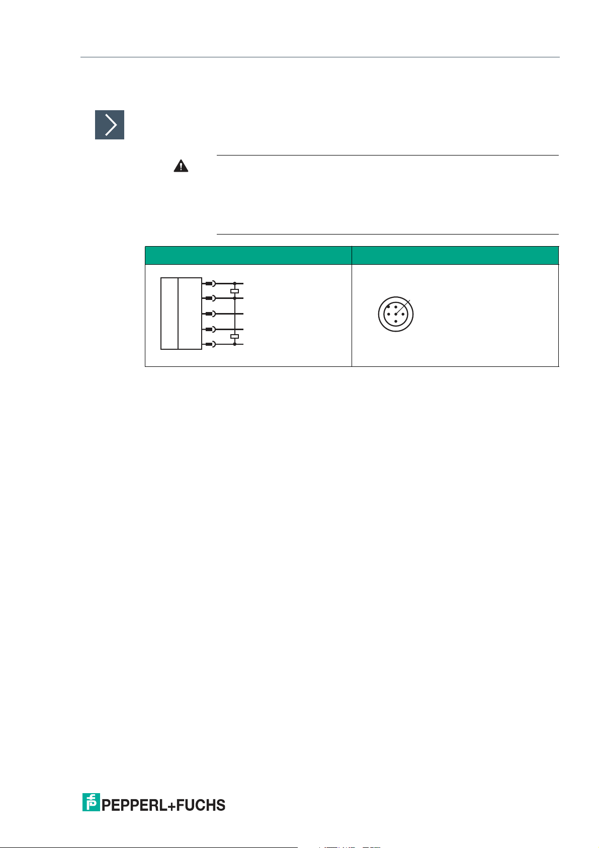
3.3 Electrical Connection
Use a suitable connection cable to connect the rotary encoder to the higher-level control panel,
an IO-Link master, or the IO-Link-Master02-USB.
Caution!
No voltage permitted at Pin 2!
The ENAxxTL-...IO-... product group does not support functionality for Pin 2 in
terms of a digital input / output. However, there is a real physical connection to
the PCB. Application of voltage potential is therefore not permitted. It could
cause the device to malfunction.
Electrical Connection Pinout
Table 3.1
2020-09
13
Page 14

ENA**TL-**IO**
Commissioning
4 Commissioning
4.1 Commissioning with IO-Link on a Control Panel (Online Parameterization)
Note
The device description file (IODD) required for integration in an IO-Link system and for
param eterization and diagnostics is available online. Visit www.pepperl-fuchs.com and
navigate to the relevant product page for the ENA***TL-**IO**.
To activate the absolute rotary encoder via IO-Link using a control panel, proceed as follows:
1.
Check the connection between the absolute rotary encoder and the IO-Link master.
2.
Set the status to "IO-Link" on the corresponding port on the IO-Link master to w hich the
absolute rotary encoder is connected.
3.
Once communication has been successfully established, the green operating indicator LED on
the absolute rotary encoder will flash briefly in one-second intervals.
The absolute rotary encoder can now either be parameterized using the IO-Link configura-
tion tool or diagnosed using the modulated application. The device sends the binary switching information and the position value as process data.
4.2 Commissioning with IO-Link via FTD Framework Program (Offline Parameterization)
IO-Link Offline Parameterization Tool
An IODD (IO-Link Device Description) file is available to download for parameterization of the
absolute rotary encoder via IO-Link and diagnosis. See the product page for the relevant
ENA***TL-**IO** absolute rotary encoder online at www.pepperl-fuchs.com or use the
IODDfinder at https://iodfinder.io-link/com/.
For offline parameterization, IO-Link devices are already configured before mounting. To do
this, you can use the Pepperl+Fuchs IO-Link USB master.
The software components required in each case are summarized in the "IO-Link Offline Parameterization Tool" software package in their most current versions. The software package can be
found online at www.pepperl-fuchs.com along with the corresponding documentation regarding installation and use.
If you use the "IO -Link Offline Parameterization Tool" software package, have active Internet
access, and have connected your device via the Pepperl+Fuchs IO-Link USB master, you can
integrate the IODD directly into the IO-Link Offline Parameterization Tool via the "IODD DTM
Configurator."
14
Note
A 5-pin M12 cordset is needed to connect the absolute rotary encoder to the Pepperl+Fuchs
IO-Link master. Visit www.pepperl-fuchs.com and click on the product page for the relevant
absolute rotary encoder to find suitable cordsets.
2020-09
Page 15

ENA**TL-**IO**
Commissioning
To activate the absolute rotary encoder via IO-Link using the corresponding IODD, proceed as
follows:
1.
Make sure that the "IO -Link Offline Parameterization Tool" software package is installed on your
computer.
2.
Connect the absolute rotary encoder to an IO-Link master via a suitable M12 cordset.
3.
Connect the IO-Link master to a USB connection on your PC via a USB cable.
4.
Start PACTware.
PACTware autom atically communicates with the absolute rotary encoder if you are using
PACTware from the "IO-Link Offline Parameterization Tool" and automatically found the
IODD online.
2020-09
15
Page 16

ENA**TL-**IO**
Process Data Structure
5 Process Data Structure
The process data of the absolute rotary encoder consists of 96 bits (12 bytes). The following
table provides an overview of the order and structure of the process data.
Data
Name Long Name
MDC2 - Auxiliar y
Measurement
MDC1 -Position Measurement Data
MDC1 - Resolution
(STR)
Reserved – – 6 bits 10 0 = Low
DSC1.2 -Temperature Warning 2
DSC1.1 -Temperature Warning 1
Status - Auxiliary
Measurement
MDC2
Reserved – – 1 bit 3 0 = Low
Status - Count
Direction
SSC2 - Switching
Signal 2
SSC1 - Switching
Signal 1
Table 5.1
Measurement Data
Channel 2 - Auxiliary
Measurement
Channel 1 - Position
Measurement Data
Channel 1 - Singleturn Resolution
Diagnosis Signal
Channel 1.2 - Temperature Warning 1
Diagnosis Signal
Channel 1.1 - Temperature Warning 2
Status - Auxiliary
Measurement Data
Channel 2
– Boolean 1 bit 2 0 = Low
Switching Signal
Channel 2
Switching Signal
Channel 1
Type Length
Integer 32 bits 64 0 <MV2-
Integer 32 bits 32 0
UInteger 16 bits 16 1 <MV1_S-
Boolean 1 bit 9 0 = Low
Boolean 1 bit 8 0 = Low
UInteger 4 bits 4 0 = Low
Boolean 1 bit 1 0 = Low
Boolean 1 bit 0 0 = Low
Bit
Offset Value Com ment
max>
<MV1_Posmax>
calem ax>
1 = High
1 = High
1 = High
1 = High
1 = High
1 = High
Additional measured
value. Either deactivated or corresponds
to the ambient temperature of the device
0 = Increase
1 = Decrease
16
2020-09
Page 17

ENA**TL-**IO**
00
shaft
3000
6000
9000
shaft
250
500
750
Index Bitoffset Parameter Value
(Process data)
- 32 MDC1-Position 875
0x60 - Config-ST Resolution 1000
Index Bitoffset Parameter Value
(Process data)
- 32 MDC1-Position 10500
0x60 - Config-ST Resolution 12000
Position
Singleturn version
Position
Singleturn version
Process Data Structure
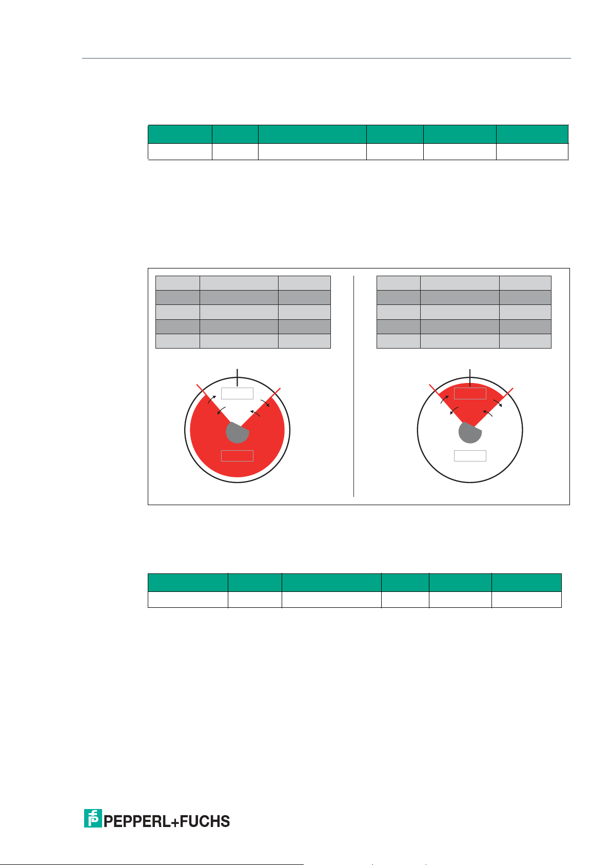
5.1 Config - ST Resolution
Configuration Singleturn Resolution
Index Sub Parameter Access Data Type Length
96 (0x60) — Config - ST Resolution rw UInteger 16 bits
The "Config - ST Resolution" parameter is used to set the resolution of the rotary encoder. The
resolution refers to the singleturn resolution. Consequently, this value is used to set how many
equal-sized position steps are output/counted in one revolution.
The following figure illustrates this with an example for singleturn-only device versions.
Figure 5.1 Identical shaft posi tion with different singleturn resolutions
A singleturn resolution of 1000 is selected on the left and 12,000 on the right. The physical
shaft position is the same on the left and right (see "shaft"). However, the "MDC1 - Position"
process data show different data on the left and right. This is explained by the division of a full
revolution into 1000 steps in one case and into 12,000 steps in the other.
The figure below illustrates this with an example for multiturn device versions.
2020-09
17
Page 18

ENA**TL-**IO**
10000
shaft
1250
1500
1750
shaft
250
500
750
Index Bitoffset Parameter Value
(Process data)
- 32 MDC1-Position 875
0x60 - Config-ST Resolution 1000
Index Bitoffset Parameter Value
(Process data)
- 32 MDC1-Position 1875
0x60 - Config-ST Resolution 1000
Shaft position
exceeds zero
position
Position
Multiturn version
second revolution
Position
Multiturn version
first revolution
Process Data Structure
Figure 5.2 Different shaft position for multiturn versions depending on singleturn resolutions
The example also shows that the current shaft position (= MDC1 - Position) and the set singleturn resolution (= Config - ST Resolution = MDC1 - ST Resolution) can be used to determine
the corresponding multiturn position (= number of full revolutions completed). If a complete revolution means 1000 steps, a measured value equating to MDC1 - Position = 1875 means that
one full revolution and a further 875 steps of the next revolution have been completed.
Refer to information on the "MDC1 - ST Resolution" process data content and the "Config Position Overflow" parameter.
5.2 MDC1 - Position
Measurement Data Channel 1 - Position
The "MDC1 - Position" process data content returns the current absolute shaft position. If the
shaft is rotated when the device is disconnected from the power supply, the new shaft position
is updated and immediately available once the device is switched on again.
The number of measuring steps that are counted in one revolution can be set as required.
Refer to information on the "Config - ST Resolution" and "Position Value - Overflow" parameters.
5.3 MDC1 - ST Resolution
Measurement Data Channel 1 - Singleturn Resolution
The "MDC1 - ST Resolution" process data content describes the singleturn resolution and corresponds to the value set as the "Config - ST Resolution" parameter.
This value determines how many measuring steps are counted in one full revolution.
Refer to information on the "Config - ST Resolution" parameter.
The cyclical transmission of the set singleturn resolution offers significant added value in condition monitoring applications. The position value from the "MDC1 - Position" process data can
be more easily interpreted.
The "MDC1 - ST Resolution" process data can be used to calculate the current multiturn position at any time for all multiturn versions.
The following figure illustrates this with an example for singleturn-only device versions.
18
2020-09
Page 19

ENA**TL-**IO**
00
shaft
3000
6000
9000
shaft
250
500
750
Index Bitoffset Parameter Value
(Process data)
- 32 MDC1-Position 875
0x60 - Config-ST Resolution 1000
Index Bitoffset Parameter Value
(Process data)
- 32 MDC1-Position 10500
0x60 - Config-ST Resolution 12000
Position
Singleturn version
Position
Singleturn version
10000
shaft
1250
1500
1750
shaft
250
500
750
Index Bitoffset Parameter Value
(Process data)
- 32 MDC1-Position 875
0x60 - Config-ST Resolution 1000
Index Bitoffset Parameter Value
(Process data)
- 32 MDC1-Position 1875
0x60 - Config-ST Resolution 1000
Shaft position
exceeds zero
position
Position
Multiturn version
second revolution
Position
Multiturn version
first revolution
Process Data Structure
Figure 5.3 Identical shaft posi tion with different singleturn resolutions
A singleturn resolution of 1000 is selected on the left and 12,000 on the right. The physical
shaft position is the same on the left and right (see "shaft"). However, the "MDC1 - Position"
process data show different data on the left and right. This is explained by the division of a full
revolution into 1000 steps in one case and into 12,000 steps in the other.
The figure below illustrates this with an example for multiturn device versions.
2020-09
Figure 5.4 Different shaft position for multiturn versions depending on singleturn resolutions
The example also shows that the current shaft position (= MDC1 - Position) and the set singleturn resolution (= Config - ST Resolution = MDC1 - ST Resolution) can be used to determine
the corresponding multiturn position (= number of full revolutions completed). If a complete revolution means 1000 steps, a measured value equating to MDC1 - Position = 1875 means that
one full revolution and a further 875 steps of the next revolution have been completed.
Refer to information on the "MDC1 - ST Resolution" process data content and the "Config Position Over flow" parameter.
19
Page 20

ENA**TL-**IO**
Process Data Structure
A Mathematical Generalization for this Relationship
• Singleturn resolution = Config - ST Resolution = number of measuring steps per revolu-
• Multiturn position = number of full revolutions already completed
• Modulo corresponds to the remainder function
[Measuring steps per revolution] x [multiturn position] + remainder = [MDC1 - position]
[MDC1 - position] mod [measuring steps per revolution] = remainder of division [MDC1 - position] / [measuring steps per revolution]
([MDC1 - position] - remainder) / [measuring steps per revolution]) = [multiturn position]
tion
• A mod B = remainder of division A / B
• Where if A is less than or equal to B: A mod B = 0
For the purposes of simplification, "rem ainder of division ..." is subsequently abbreviated
as simply "remainder."
If [MDC1 - position] - remainder [measuring steps per revolution] — ([MDC1 - position] remainder) / [measuring steps per revolution] = 0 by definition)
Taking the sample numbers from above, the result is:
• Singleturn resolution = Config - ST Resolution = MDC1- ST Resolution = number of mea-
suring steps per revolution = 1000
• Multiturn position = number of full revolutions already completed = ?
1000 x ? = 1875
1875 mod 1000 = remainder of division 1875 / 1000 — 875
(1875 - 875) / 1000 = ? equates to ? = 1
— The rotary encoder has completed one full revolution. It is currently 875 steps into the next
revolution.
5.4 SSC1 - Switching Signal 1
Switching Signal Channel 1
The "SSC1 - Switching Signal 1" process data content refers to a signal bit used to detect a
position that is critical for the application. It is part of the cyclic signal transmission. The signal
bit can toggle between "0" and "1" depending on the status of the absolute rotary encoder or of
the application.
The following parameters influence the switching characteristics of the SSC1 process data:
• SSC1 Param. SP1
20
• SSC1 Param. SP2
• SSC1 Config. Logic
• SSC1 Config. Mode
• SSC1 Config. Hyst
2020-09
Page 21

ENA**TL-**IO**
Process Data Structure
5.5 SSC2 - Switching Signal 2
Switching Signal Channel 2
The process data content "SSC2 - Switching Signal 2" describes a signal bit that is used to
detect a position that is critical for the application. It is part of the cyclic signal transmission. The
signal bit can toggle between "0" and "1" depending on the status of the absolute rotary
encoder or of the application.
The SSC2 process data is functionally redundant to the SSC1 process data. It should be
regarded as an independent supplement to this data.
The following parameters influence the switching characteristics of the SSC2 process data:
• SSC2 Param. SP1
• SSC2 Param. SP2
• SSC2 Config. Logic
• SSC2 Config. Mode
• SSC2 Config. Hyst
5.6 Status - Count Direction
The "Status - Count Direction" process data content indicates the current direction of rotation of
the shaft. It is transmitted cyclically and you can use the "Config - Rotation Direction" parameter
to adjust the settings for the process da ta.
The "Status - Count Direction" process data content can distinguish between the "increase"
and "decrease" values depending on the setting and the current direction of rotation.
5.7 MDC2 - Auxiliary Measurement
Measurement Data Channel 2 - Auxiliary Measurement
The "MDC2 - Auxiliary Measurement" process data content describes another available measured value that can be read out from the device.
For the ENA***TL-**IO ** product group, this additional measured value is the ambient temperature of the device. The cyclical transmission of an additional measured value offers significant
added value in condition monitoring applications. The content can be set to "deactivated,"
meaning that the measured value is always 0.
Refer to information on the "Config - Auxiliary Measurement" parameter.
5.8 Status - Auxiliary Measurement MCD2
Measurement Data Channel 2 - Auxiliary Measurement
The process data in "Status - Auxiliary Measurement MDC2" indicates which measured value
is transmitted via "MDC2 - Auxiliary Measu rement."
The following options are supported:
• "Deactivated" (0) >> m easured value is always 0
• "Temperature" (1) >> ambient temperature
This informa tion is beneficial when evaluating process data remotely, and the exact device setting for the rotary encoder is not known or if several devices with different settings are used
simultaneously.
For the ENA***TL-**IO** product group, this additional measured value is either disabled or
corresponds to the device's outside tem perature.
2020-09
21
Page 22

ENA**TL-**IO**
Process Data Structure
5.9 DSC1.1 - Temperature Warning 1
Diagnosis Signal Channel 1.1 - Temperature Warning 1
The "DSC Temperature Warning 1" data display indicates whether or not a critical upper temperature limit has been exceeded.
Refer to information on the following parameters
• DSC1.1 Param - Temperature: High Limit
• DSC1 Config - Temperature: Mode
• DSC1 Config - Temperature: Logic
• DSC1 Config - Temperature: Hyst
5.10 DSC1.2 — Temperature Warning 2
Diagnosis Signal Channel1.2 — Temperature Warning 2
The "DSC — Temperature Warning 2" process data status indicates whether or not a critical
low temperature has been reached.
Compare w ith information relating to the parameters:
• DSC1.2 Param — Temperature: Low Limit
• DSC1 Config — Temperature: Mode
• DSC1 Config — Temperature: Logic
• DSC1 Config — Temperature: Hyst
22
2020-09
Page 23

ENA**TL-**IO**
00
shaft
3000
6000
9000
shaft
250
500
750
Index Bitoffset Parameter Value
(Process data)
- 32 MDC1-Position 875
0x60 - Config-ST Resolution 1000
Index Bitoffset Parameter Value
(Process data)
- 32 MDC1-Position 10500
0x60 - Config-ST Resolution 12000
Position
Singleturn version
Position
Singleturn version
IO-Link Parameterization
6 IO-Link Parameterization
Only the parameters of the ENA***TL-**IO** product group that require explanation are listed
below.
Note
A comprehensive overview of all parameters for the respective absolute rotary encoder can be
found online at www.pepperl-fuchs.com. Navigate to the relevant product page for the
ENA***TL-**IO** and click on the corresponding "IO-Link parameter data sheet" document.
The abbreviations below are used in the following:
ro read only
wo write only
rw read and write
6.1 Config - ST Resolution
Configuration Singleturn Resolution
Index Sub Parameter Access Data Type Length
96 (0x60) — C onfig - ST Resolution rw UInteger 16 bits
The "Config - ST Resolution" parameter is used to set the resolution of the rotary encoder. The
resolution refers to the singleturn resolution. Consequently, this value is used to set how ma ny
equal-sized position steps are output/counted in one revolution.
The following figure illustrates this with an example for singleturn-only device versions.
Figure 6.1 Identical shaft pos ition with different singleturn resolution s
A singleturn resolution of 1000 is selected on the left and 12,000 on the right. The physical
shaft position is the same on the left and right (see "shaft"). However, the "MDC1 - Position"
process data show different data on the left and right. This is explained by the division of a full
revolution into 1000 steps in one case and into 12,000 steps in the other.
The figure below illustrates this with an example for multiturn device versions.
22
2020-09
Page 24

ENA**TL-**IO**
10000
shaft
1250
1500
1750
shaft
250
500
750
Index Bitoffset Parameter Value
(Process data)
- 32 MDC1-Position 875
0x60 - Config-ST Resolution 1000
Index Bitoffset Parameter Value
(Process data)
- 32 MDC1-Position 1875
0x60 - Config-ST Resolution 1000
Shaft position
exceeds zero
position
Position
Multiturn version
second revolution
Position
Multiturn version
first revolution
IO-Link Parameterization
Figure 6.2 Different shaft position for multiturn versions depending on singleturn resolutions
The example also shows that the current shaft position (= MDC1 - Position) and the set singleturn resolution (= Config - ST Resolution = MDC1 - ST Resolution) can be used to determine
the corresponding multiturn position (= number of full revolutions completed). If a complete revolution means 1000 steps, a measured value equating to MDC1 - Position = 1875 means that
one full revolution and a further 875 steps of the next revolution have been completed.
Refer to information on the "MDC1 - ST Resolution" process data content and the "Config Position Over flow" parameter.
6.2 SSC1 Param. SP1
Switching Signal Channel 1 Parameter Setpoint 1
Index Sub Parameter Access Data Type Length
64 (0x40) 1 SSC1 Param. SP1 rw Integer 32 bits
The "SSC1 Param. SP1" parameter is used to set a critical limit value for "SSC1."
The permissible value range of the "SSC1 Param. SP1" parameter is independent of "SSC1
Param. SP2."
2020-09
23
Page 25

ENA**TL-**IO**
SP2= 900
SP1= 100
0
shaft
Switch
Switch
Index Parameter Value
0x40 Sub 1 SSC1 Param. SP 1 100
0x40 Sub 2 SSC1 Param. SP 2 900
0x60 Config-ST Resolution 1000
IO-Link Parameterization
6.3 SSC1 Param. SP2
Switching Signal Channel 1 Parameter. Setpoint 2
Index Sub Parameter Access Data Type Length
64 (0x40) 2 SSC1 Param. SP2 rw Integer 32 bits
The "SSC1 Param. SP2" parameter is used to set a critical limit value for "SSC1."
The permissible value range of the "SSC1 Param. SP2" param eter is independent of "SSC1
Param. SP1." see chapter 6.2 for a comparison.
The figure below uses an example to illustrate the relationship between SP1 and SP2.
Figure 6.3
The general rule for switch points SP1 and SP2 is that
switch points SP1 and SP2 can be set independently of each other:
• SP1 can be greater than SP2.
• SP1 can be smaller than SP2.
• SP1 can be equal to SP2.
24
2020-09
Page 26
ENA**TL-**IO**
SP2= 900
SP1= 100
0
shaft
Switch
Switch
SP2= 900
SP1= 100
0
shaft
Switch
Switch
high active
low active
low active
high active
Index Parameter Value
0x40 Sub 1 SSC1 Param. SP 1 100
0x40 Sub 2 SSC1 Param. SP 2 900
0x41 Sub 1 SSC1 Config. Logic 0 (high active)
0x60 Config-ST Resolution 1000
Index Parameter Value
0x40 Sub 1 SSC1 Param. SP 1 100
0x40 Sub 2 SSC1 Param. P 2 900
0x41 Sub 1 SSC1 Config. Logic 0 (low active)
0x60 Config-ST Resolution 1000
IO-Link Parameterization
6.4 SSC1 Config. Logic
Switching Signal Channel 1 Configuration Logic
Index Sub Parameter Access Data Type Length
65 (0x41) 1 SSC1 Config. Logic rw UInteger 8 bits
The "SSC1 Config. Logic" parameter indicates whether the "SSC1" switching signal is transmitted as "High active" or "Low active."
You can use this parameter to specify which range between "SSC1 Param. SP2" and "SSC1
Param. SP1" is transmitted as "High active" or "Low active." The approach used means that if
the switch points in the default setting are exceeded or are not reached, this results in a high
active signal.
The figure below illustrates this.
Figure 6.4
6.5 SSC1 Config. Mode
Switching Signal Channel 1 Configuration. Mode
Index Sub Parameter Access Data Type Length
65 (0x41) 2 SSC1 Config. Mode rw UInteger 8 bits
The "SSC1 Config. Mode" parameter is used to set the evaluation mode for the signal evalua-
2020-09
tion. The resulting switching signal depends on values selected for SP1 and SP2 for Logic and
Mode.
Set one of the following modes:
• Deactivated
• Single Point
• Window
• Two Point
25
Page 27

ENA**TL-**IO**
SP.max
SSC
SP.min
SP 2 SP 1
inactive
active
SP.max
SSC
SP.min
SP 2 SP 1
inactive
active
SP.max
SSC
SP.min
SP 2 SP 1
inactive
active
SP.max
SSC
SP.min
SP 2 SP 1
inactive
active
IO-Link Parameterization
The figures below show the different modes; switching signal "SSC1" is shown as a blue line.
"Deactivated" Mode
Figure 6.5
Single Point Mode as High Active Signal
Figure 6.6
Window Mode as High Active Signal
Figure 6.7
Two Point Mode as High Active Signal
Figure 6.8
26
2020-09
Page 28

ENA**TL-**IO**
SP.max
SSC
SP.min
SP 2 SP 1
inactive
active
hysteresis
SP.max
SSC
SP.min
SP 2 SP 1
inactive
active
hysteresis
IO-Link Parameterization
6.6 SSC1 Config. Hyst
Switching Signal Channel 1 Configuration Hysteresis
Index Sub Parameter Access Data Type Length
65 (0x41) 3 SSC1 Config. Hyst rw Integer 16 bits
The "SSC1 Config. Hysteresis" parameter indicates the extent of a desired delayed effect of the
SSC1 bit. This is despite an actual change made to the position value.
If the measured position value continuously toggles around the set critical setpoint "SSC1
Param. SP1," the SSC1 signal bit in the cyclic signal transmission would continuously toggle
between "0" and "1." If this effect is not required, use the "SSC1 Config. Hysteresis" param eter
to create an interval between the activation (1) and deactivation (0) of the SSC1 bit.
The hysteresis function depends on the mode selected in the "SSC1 Config. Mode" parameter.
It is effective for the "Single Point" and "Window" modes only. The effect in each mode is shown
in the figures below.
Single Point Mode with Hysteresis as High Active Signal
Figure 6.9
Window Mode with Hysteresis as High Active Signal
Figure 6.10
As seen in the "Window" mode figure, the hysteresis limit for Window mode has an outwardfacing effect. As seen in the "Single Point" figure, this sensing principle is used for Single Point
mode.
The example below illustrates this sensing principle, showing a frontal view of the rotar y
encoder shaft and the corresponding positive direction of rotation set to clockwise.
2020-09
27
Page 29
ENA**TL-**IO**
Position se
ctor 1
P
osition sector 4
Position sector 3
Position
sector 2
0
Switch
Switch
Switch
Switch
Switch
Switch
shaft
Switch
Switch
high active
SP2
SP1
Hyst. limit
Hyst. limit
l
o
w
a
cti
v
e
Bitoffset Parameter Value
(Process data)
0x40 Sub 3 Switchpoint Hysteresis 300
0x40 Sub 2 SSC1 Param. SP 2 200
0x40 Sub 1 SSC1 Param. SP 1 500
0x60 Config-ST Resolution 1000
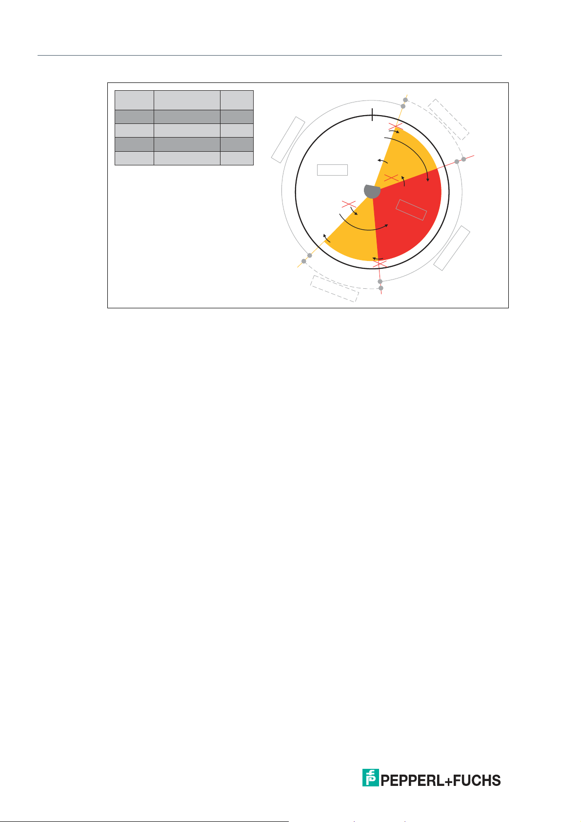
IO-Link Parameterization
Figure 6.11 Switching point characteristics with hysteresis area larger than the overflow lim it
Position
White section = area outside the hysteresis areas and the setpoints
sector 1
Position
Yellow section = hysteresis area of the smaller setpoint
sector 2
Position
Red section = area between setpoint 1 and setpoint 2
sector 3
Position
Yellow section = hysteresis area of the larger setpoint
sector 4
28
2020-09
Page 30

ENA**TL-**IO**
IO-Link Parameterization
The following table shows the respective switching characteristics for each combination. It is
necessaryto distinguish between the position sector (see previous figure) that is changed to
the next position sector and the status of the switching channel has shortly before the sector
change.
MDC1 — Position Switching Charac-
1 high 2 high –> high
2 high 3 high –> low
2 low 3 low – > low
3 low 4 low – > low
4 low 1 low – > high
4 high 1 high –> high
1 high 4 high –> high
4 high 3 high –> low
4 low 3 low – > low
3 low 2 low – > low
2 low 1 low – > high
2 high 1 high –> high
Table 6.1
teristics of SSC1
Switching Signal 1From "Position Sector" SSC1 Value To "Position Sector"
If the position sector is changed from sector 4 (SP1 hysteresis area) to sector 3 (= inner window area) and the SSC1 switching channel is about to switch to "high," SSC1 will switch its
contents to "low" if sector 4 exceeds sector 3.
You can set the desired measuring range as "high active" or "low active" using the "SSC1 Config Logic" (0x41 Sub 1) parameter.
These switching characteristics apply to the singlepoint mode if the "SSC 1 Config Mode"
(0x41 Sub 2) parameter is set to "Single point."
6.7 Config - Auxiliary Measurement
Configuration - Auxiliary Measurement
Index Sub Parameter Access Data Type Length
101 (0x65) – Config - Auxiliary Measurement rw UInteger 8 bits
The "Config - Auxiliary Measurement" parameter is used to set whether an additional measured value is transferred in the cyclical process data word. For the ENA***TL-**IO** product
group, this additional measured value is the ambient temperature of the device.
2020-09
29
Page 31

ENA**TL-**IO**
IO-Link Parameterization
6.8 Config — Rotation Direction
Configuration — Rotation Direction
Index Sub Parameter Access Data Type Length
97 (0x61) – Config — Rotation Direction rw UInteger 8 bits
The "Config — Rotation Direction" parameter defines the positive counting direction when the
rotary encoder shaft is rotated. Either "Clockwise" or "Counter clockwise" can be selected as a
positive counting direction.
Example: When looking at the rotary encoder shaft, the "Counter clockwise" setting produces a
positive counter-clockwise counting direction.
Figure 6.12
6.9 Config - Position Preset
Configuration - Position Preset
Index Sub Parameter Access Data Type Length
99 (0x63) Config - Position Preset rw Integer 32 bits
The "Config - Position P reset" parameter is used to offset the zero crossing.
This value can be used to redefine a suitable zero crossing during operation or for a particular
installation situation. Even after switching the rotary encoder off and on again (Power cycle) ,
this value is the valid zero crossing since it is permanently stored in the device. The "Config Position Preset" parameter can be set to values other than "0."
When the "Position Preset" command (170, 0x63) is triggered, the set value of the "Config Position Preset" parameter is applied for this current position. All changes to the position are
relative to this position value.
30
2020-09
Page 32

ENA**TL-**IO**
Overflow
=
2250
0
shaft
0
shaft
1000
shaft
2000
shaft
Index Parameter Value
0x64 Config-Position Overflow 2250
0x60 Config-STR Resolution 1000
Shaft position
exceeds Overflow
Start first application cycle Start next application cycle
first encoder
revolution
second encoder
revolution
partial
revolution
IO-Link Parameterization
6.10 Config - Position Overflow
Configuration - Position Overflow
Index Sub Param eter Access Data Type Length
100 (0x64) Config - Position Overflow rw Integer 32 bits
The "Config - Position Overflow" parameter is used to set the highest position value for the current measured position value.
As soon as the "Position Overflow" value is exceeded, the position value reverts to "0" and continues counting up from there. Conversely, as soon as the position value falls below "0," the
measured value jumps to the "Position Overflow" value and continues counting down from
there. This is used for cyclical applications with a consistent direction of rotation (e.g., winding
paper rolls).
The figure below illustrates this.
Figure 6.13 Switching point characteristics with overflow function
The maxim um permissible multiturn position of the encoder is set using the "Config - Position
Overflow" setting. This parameter can therefore also be considered as a total resolution in addition to "Config - ST Resolution." The figure above shows that two full revolutions are possible.
The third revolution is counted upward by a further 1/4. Once the overflow value has been
exceeded, the position value begins counting again from zero.
A Mathematical Generalization for this Relationship
• Singleturn resolution = Config - ST Resolution = number of measuring steps per revolu-
tion
• Maximum possible multiturn position = maximum number of possible full revolutions
(Config - Position Overflow) / (Config - ST Resolution)
—?round off the result = (maximum possible multiturn position)
In addition:
2020-09
"Config - Position O verflow" must always be greater than or equal to "Config - ST Resolution"
Taking the sample num bers from the illustration above, the result is:
• Singleturn resolution = Config - ST Resolution = MDC1 Resolution = number of measur-
ing steps per revolution = 1000
31
Page 33

ENA**TL-**IO**
IO-Link Parameterization
• Config - Position Overflow maximum number of possible measuring steps over all revolu-
tions = 2250
• Maximum possible m ultiturn position = maximum number of possible full revolutions = ?
1000 x ? = 2250
2250 / 1000 = 2.25 rounded = 2
Selecting Config - ST Resolution = 1000 and Config - Position Overflow = 2250 means that two
full revolutions can be completed before the rotary encoder starts counting again from ZERO,
by maintaining an upward counting direction of rotation. The third revolution is started in this
example but is only a partial revolution since counting begins again from ZERO from the 2250
position.
6.11 DSC1.1 Param - Temperature. High Limit
Diagnosis Signal Channel 1.1 Parameter - Temperature: High Limit
Index Sub Parameter Access Data Type Length
80 (0x50) 1 DSC1.1 Param -
Temperature.
High Limit
rw Integer 16 bits
The "DSC1.1 Param - Temperature. High Limit" param eter is used to set the upper temperature
limit value and corresponds to the switching threshold of the "DSC1.1 - Temperature Warning
1" switching alarm signal in the process data word.
6.12 DSC1.2 Param - Temperature. Low Limit
Diagnosis Signal Channel 1.1 Parameter - Temperature: Low Limit
Index Sub Parameter Access Data Type Length
80 (0x50) 2 DSC1.1 Param -
Temperature.
Low Limit
The "DSC1.2 Param - Temperature. Low Limit" parameter is used to set the lower temperature
limit value and corresponds to the switching threshold of the "DSC1.2 - Temperature Warning
2" switching alarm signal in the process data word. The "DSC1.2 Param - Temperature. Low
Limit" parameter can be activated simultaneously to the "DSC1.1 Param - Temperature. High
Limit" parameter.
rw Integer 16 bits
32
2020-09
Page 34

ENA**TL-**IO**
Temp.maxTemp.min
Temp.
high limit
DSC1.1
Temp. Warning 1
inactive
active
hysteresis
Temperature
IO-Link Parameterization
6.13 DSC1 Config — Temperature. Logic
Diagnosis Signal Channel 1.1 Configuration — Temperature: Logic
Index Sub Parameter Access D ata Type Length
81 (0x51) 1 DSC1 Config — Temperatu re. Logic rw UInteger 8 bits
The "DSC1 Config — Temperature. Logic" parameter describes whether the "DSC1.1 Param
— Temperature.High Limit" and "DSC1.2 Param — Temperature. Low Limit" signal bits are
transmitted as "High active" or "Low active."
6.14 DSC1 Config - Temperature. Mode
Diagnosis Signal Channel 1.1 Configuration - Temperature: Mode
Index Sub Parameter Access Data Type Length
81 (0x51) 2 DSC1 Config - Temperature. Mode rw UInteger 8 bits
The "DSC1 Config - Temperature. Mode" parameter describes whether only the "DSC1.1
Param - Temperature. High Limit" signal bit or additionally the "DSC1.2 Param - Temperature.
Low Limit" signal bit is activated in the process data word.
6.15 DSC1 Config - Temperature. Hyst
Diagnosis Signal Channel 1 Configuration - Temperature Hysteresis
Index Sub Parameter Access Data Type Length
81 (0x51) 3 DSC1 Config: Temperature. Hyst rw Integer 16 bits
The "DSC1 Config: Temperature. Hyst" parameter is used to set the required delayed effect of
the "DSC1.1 Param - Temperature. High Limit" and "DSC1.2 Param - Temperature. Low Limit"
signal bits despite a real change in the temperature value. This is used if the continuous switching of the signal bits should be suppressed when the real temperature value toggles around the
set threshold value.
The figure below shows the respective effect of the set hysteresis as an example for the " High
Limit Active" and "High and Low Limit Active" modes.
Hysteresis in "High Limit Active" mode as active high signal
Figure 6.14
2020-09
33
Page 35

ENA**TL-**IO**
Temp.maxTemp.min
Temp.
low limit
Temp.
high limit
DSC1.2
Temp. Warning 2
DSC1.1
Temp. Warning 1
inactive
active
hysteresis
Temperature
IO-Link Parameterization
Hysteresis in "High and Low Limit Active" mode as active high signal
Figure 6.15
34
2020-09
Page 36

ENA**TL-**IO**
SP1= 900
SP2= 100
SP2= SP1= 100
SP2= 900
SP1= 100
Switch
00 0
shaft
Switch
Switch
shaftshaft
Switch
Switch
Index Parameter Value
0x40 Sub 1 SSC1 Param. SP 1 100
0x40 Sub 2 SSC1 Param. SP 2 900
0x60 Config-ST Resolution 1000
Index Parameter Value
0x40 Sub 1 SSC1 Param. SP1 100
0x40 Sub 2 SSC1 Param. SP 2 100
0x60 Config-ST Resolution 1000
Index Parameter Value
0x40 Sub 1 SSC1 Param. SP 1 900
0x40 Sub 2 SSC1 Param. SP 2 100
0x60 Config-ST Resolution 1000
Switching Signal Characteristics
7 Switching Signal Characteristics
The following sections use examples to describe the switching signal characteristics of the
rotary encoder for the "SSC1 - Switching Signal 1" process data. The switching signal characteristics for the "SSC2 - Switching Signal 2" process data work in the same way. You can set
and use both switching signal channels independently of each other.
7.1 Window Mode with SP1 and SP2
The parameters of SP1 (setpoint 1) and SP2 (setpoint 2) can be set differently, to accommodate different application types. The figure below illustrates this.
Figure 7.1
The SP1 (setpoint 1) and SP2 (setpoint 2) switch points can be used as the upper or lower
switching threshold for the associated switching signal channel, depending on the assigned
value. The switch point with the higher value is referred to as the upper switching limit; the
switch point with the lower value is referred to as the lower switching limit. The colored value
range between the lower and upper switching limit is known as the window range.
SP1 (setpoint 1) and SP2 (setpoint 2) can be configured with the same assigned value and
loaded into the device. However, since the upper and lower switching limits have the same
value, the switching signal channel does not indicate any change if this value is exceeded or is
not reached.
The "SSC 1 Config. Logic" parameter (0x41 Sub 1) can be used to set the required switching
characteristics to "High active" or "Low active."
The general rule for switch points SP1 and SP2 is
Switch points SP1 and SP2 can be set independently of one another.
• SP1 can be greater than SP2
• SP1 can be smaller than SP2
• SP1 can be equal to SP2
2020-09
33
Page 37

ENA**TL-**IO**
SP2= 1400
SP1= 1950
shaft
Overflow
= 1850
Switch
Switch
SP2
= 1400
SP1= 1950
shaft
Overflow= 1850
Switch
Switch
Shaft position
exceeds Overflow
1000
Start next cycle
0
1000
Index Parameter Value
0x64 Config-Position Overflow 1850
0x40 Sub 2 SSC1 Param. SP 2 1400
0x40 Sub 1 SSC1 Param. SP 1 1950
0x60 Config-ST Resolution 1000
Switching Signal Characteristics
7.2 Position Overflow with SP1 and SP2
You can set the SP1 (setpoint 1) and SP2 (setpoint 2) switch point values to be higher than the
value for the "Config — Position Overflow" param eter (0x64). This setting is accepted by the
rotary encoder as a permissible parameterization status. However, the "Config — Position
Overflow" parameter automatically acts as a switching threshold when the measured value is
exceeded during operation. This is due to the functional behavior of this pa rameter. If rotation
with a positive counting direction is maintained and the "Config — Position Overflow" limit is
exceeded, the measured position value (MDC1 — Position) is automatically set to "0" at this
shaft position. The measured position value will continue to increase. Therefore, the switch
point with a higher value than the "Config — Position Overflow" parameter is effectively never
reached.
The figure below illustrates this.
34
Figure 7.2 Switching characteristics with overflow function
In this example, the selected SP1 of 1950 is higher than the "Position Overflow" set at 1850.
The SSC1 (Switching Signal Channel 1) process data changes its status when the position
measurement is exceeded at 1850 and never at 1950. The measuring range between 1850
and 1950, which can never be reached during live operation, is shown here using dashed lines.
The "SSC 1 Config. Logic" parameter (0x41 Sub 1) can be used to set the required measuring
range to "high active" or "low active."
This characteristic applies to single point mode if the "SSC 1 Config. Mode" parameter (0x41
Sub 2) is set to "Single Point."
The general rule for switch points SP1 and SP2 is:
If SP1 or SP2 is greater than or equal to "Position Overflow," the "Config — Position Overflow"
position acts as the switch point.
2020-09
Page 38

ENA**TL-**IO**
SP1
hi
g
h
active
Position sector 1
Position secto
r 4
Position sector 3
Position
sector 2
Switch
Switch
Switch
Switch
Switch
Switch
shaft
Switch
SP2
Hyst. limit
low active
0
Index Parameter Value
0x41 Sub 3 SSC1 Config. Hyst 300
0x40 Sub 2 SSC1 Param. SP 2 200
0x40 Sub 1 SSC1 Param. SP 1 500
0x60 Config-ST Resolution 1000
Switching Signal Characteristics
7.3 Hysteresis with SP1 and SP2 (Smaller than Zero Point)
You can set a uniform hysteresis area for each of the switch points SP1 (setpoint 1) and SP2
(setpoint 2). Keep in m ind that the window mode hysteresis limit has an outward-facing effect.
The rotary encoder accepts a hysteresis area smaller than the zero point as a permissible configuration status. However, it should be noted that the zero point automatically works as a
switching threshold when the measured value is not met during operation.
The figure below illustrates this.
Figure 7.3 Switching poi nt characteri stics with hysteresis area smaller than the zero point
Position
White section = area outside the hysteresis areas and the setpoints
sector 1
Position
Yellow section = hysteresis area of the smaller setpoint
sector 2
Position
Red section = area between setpoint 1 and setpoint 2
sector 3
Position
Yellow section = hysteresis area of the smaller setpoint
sector 4
The window mode between the switch points SP2 and SP1 is shown in red. The respective
hysteresis area for each switch point is yellow. The ineffective hysteresis area smaller than the
zero point is illustrated by the dashed lines. Depending on the current direction of rotation and
the current status of the switching channel, there is either a change or no change in the switching channel if the limits are exceeded.
The following table shows the respective switching characteristics for each combination. It is
necessaryto distinguish between the position sector (see previous figure) that is changed to
the next position sector and the status of the switching channel has shortly before the sector
change.
35
2020-09
Page 39

ENA**TL-**IO**
Switching Signal Characteristics
MDC1 — Position
From "Position
Sector" SSC1 Value
1 high 2 high –> high
2 high 3 high –> low
2 low 3 low –> low
3 low 4 low –> low
4 low 1 low –> high
4 high 1 high –> high
1 high 4 high –> high
4 high 3 high –> low
4 low 3 low –> low
3 low 2 low –> low
2 low 1 low –> high
2 high 1 high –> high
Table 7.1
If the position sector is changed from sector 4 (SP1 hysteresis area) to sector 3 (= inner window area) and the SSC1 switching channel is about to switch to "high," SSC1 will sw itch its
contents to "low" if sector 4 exceeds sector 3.
You can set the desired measuring range as "high active" or "low active" using the "SSC1 Config Logic" (0x41 Sub 1) parameter.
These switching characteristics apply to the singlepoint mode if the "SSC 1 Config Mode"
(0x41 Sub 2) parameter is set to "Single point."
To "Position
Sector"
Switching Characteristics of SSC1
Switching Signal 1
The general rule is
If the SPn-Hyst is smaller than zero for a decreasing measured value (position), the switch
point is at zero.
7.4 Hysteresis with SP1 and SP2 (Larger than Overflow)
You can set a uniform hysteresis area for each of the sw itch points SP1 (Setpoint 1) and SP2
(Setpoint 2).
Keep in mind that the window mode hysteresis limit has an outward-facing effect.
The rotary encoder accepts a hy steresis area larger than a set parameter "Config Position
Overflow" (0x64) as a permissible configuration status. However, it should be noted that the
"Config - Position Overflow" parameter automatically works as a switching threshold when the
measured value is exceeded during operation.
36
2020-09
Page 40

ENA**TL-**IO**
1000
Switch
Switch
Switch
Switch
Switch
Switch
Switch
shaft
Switch
Overflow= 1600
low active
high active
SP2
SP1
Hyst. limit
Hyst. limit
P
o
sition sector
1
Position sector 4
Position sector 3
Position sector 2
Index Parameter Value
0x64 Config-Position Overflow 1600
0x41 Sub 3 SSC1 Config. Hyst 250
0x40 Sub 1 SSC1 Param. SP 2 1300
0x40 Sub 2 SSC1 Param. SP 1 1500
0x60 Config-ST Resolution 1000
Switching Signal Characteristics
The figure below illustrates this.
Figure 7.4 Switching poi nt characteri stics with hysteresis area larger than the overflow limit
Position
White section = area outside the hysteresis areas and the setpoints
sector 1
Position
Yellow section = hysteresis area of the smaller setpoint
sector 2
Position
Red section = area between setpoint 1 and setpoint 2
sector 3
Position
Yellow section = hysteresis area of the larger setpoint
sector 4
The measuring range between the upper hysteresis limit and the overflow position is illustrated
by the dashed lines. The SSC1 (Switching Signal Channel 1) process da ta changes its status
when the position measurement is exceeded at 1600 and never greater than 1750. The measuring range between 1600 and 1750, which can never be reached during live operation, is
shown here using dashed lines.
2020-09
37
Page 41

ENA**TL-**IO**
Switching Signal Characteristics
The following table shows the respective switching characteristics for each combination. It is
necessaryto distinguish between the position sector (see previous figure) that is changed to
the next position sector and the status of the switching channel has shortly before the sector
change.
MDC1 — Position
From "Position
Sector" SSC1 Value
1 high 2 high –> high
2 high 3 high –> low
2 low 3 low –> low
3 low 4 low –> low
4 low 1 low –> high
4 high 1 high –> high
1 high 4 high –> high
4 high 3 high –> low
4 low 3 low –> low
3 low 2 low –> low
2 low 1 low –> high
2 high 1 high –> high
Table 7.2
If the position sector is changed from sector 4 (SP1 hysteresis area) to sector 3 (= inner window area) and the SSC1 switching channel is about to switch to "high," SSC1 will sw itch its
contents to "low" if sector 4 exceeds sector 3.
You can set the desired measuring range as "high active" or "low active" using the "SSC1 Config Logic" (0x41 Sub 1) parameter.
These switching characteristics apply to the singlepoint mode if the "SSC 1 Config Mode"
(0x41 Sub 2) parameter is set to "Single point."
To "Position
Sector"
Switching Characteristics of SSC1
Switching Signal 1
The general rule is
If the SPn-Hyst is larger than the "Config Position Overflow" parameter for an increasing measured value (Position), the switch point is at the position "Config Position Overflow."
2020-09
38
Page 42

ENA**TL-**IO**
Troubleshooting
8 Troubleshooting
8.1 What to Do in Case of a Fault
In case of a fault, use the following checklist to determine whether a fault with the rotary
encoder can be remedied.
If none of the information provided in the checklist solves the problem, contact Pepperl+Fuchs
via your sales office with any queries. Have details of the model number and firmware version
of the sensor ready if possible.
Checklist
Fault Cause Remedy
LED not lit up No voltage supply Verify that the absence of the voltage
The plug on the connection
cable is not correctly connected to the device plug on
the rotary encoder.
Wiring fault in the splitter or
switch cabinet
Connection cable to the rotary
encoder is damaged.
No IO-Link connection
to the rotary encoder
No IO-Link connection
to the rotary encoder
The C/Q communication port
on the sensor is not connected to the IO-Link master.
No voltage supply Verify that the absence of the voltage
supply is not the result of a local factor, such as installation work or maintenance work. Switch on the voltage
supply.
Connect the plug to the sensor and
tighten the union nut by hand.
Check the wiring carefully and repair
any faults with the wiring.
Replace the damaged connection
cable.
Make sure the C/Q communication
port is connected to the IO-Link master.
supply is not the result of a local factor, such as installation work or maintenance work. Switch on the voltage
supply.
2020-09
39
Page 43

ENA**TL-**IO**
Repair and Servicing
9 Repair and Servicing
The device must not be repaired, changed, or manipulated. In case of failure, always replace
the device with an original device.
40
2020-09
Page 44

Pepperl+Fu chs Qualit y
Download our latest policy here:
www.pepperl-fuchs.co m/quality
© Pepperl+Fuchs · Subject to modifications
www.pepperl-fuchs.com
Printed in Germany / DOCT-6723
 Loading...