

Absolute encoders ENA58IL-S***-SSI
Technical data
General specifications
Detection type magnetic sampling
Device type Absolute encoders
Linearity error ≤ ± 0.1 °
Functional safety related parameters
MTTFd 700 a at 40 °C
SYNCHRON SERIELLES INTERFACE
Model Number
ENA58IL-S***-SSI
Features
•Solid shaft
•SSI interface
•Up to 32 Bit multiturn
• Free of wear magnetic sampling
• High resolution and accuracy
• Additionally push buttons for
preset function (only model
characteristic SB2, SG2)
• Up to 4096 pulses on incremental
track
Description
The ENA58IL series are high precision encoders
with internal magnetic sampling.
This multiturn absolute encoder transmits a position
value corresponding to the shaft setting via the SSI
interface (Synchronous Serial Interface).
The control module sends a start sequence to the
absolute encoder to obtain the position data. The
rotary encoder then sends the position data
synchronous to the cycles of the control module. It
is possible to select the counting direction with the
function input.
Mission Time (T
L10 55 E+8 revolutions at 40/110 N axial/radial shaft load
Diagnostic Coverage (DC) 0 %
Electrical specifications
Operating voltage U
No-load supply current I
Power consumption P
Time delay before availability t
Output code Gray code, binary code
Code course (counting direction) adjustable
Interface
Interface type SSI ; SSI + incremental track
Resolu
tion
Single turn up to 16 Bit
Multiturn up to 16 Bit
Overall resolution up to 32 Bit
Transfer rate 0.1 ... 2 MBit/s
Cycle time < 100 µs
Standard conformity RS 422
Input 1
Input type Selection of counting direction (cw/ccw)
Signal voltage
High
Low 0 ... 2 V or unconnected (cw ascending)
Input current < 6 mA
Switch-on delay < 250 ms
Input 2
Input type zero-set (PRESET 1) with falling edge
Signal voltage
High 4.75 V ... U
Low 0 ... 2 V
Input current < 6 mA
Signal duration ≥ 1.1 s
Output
Output type RS422, Push/Pull
Signal output A+B+/A+/B
Pulses 1024, 2048, 4096
Connection
Connector M12 connector, 8-pin or M23 connector, 12-pin
Cable Ø7 mm, 6 x 2 x 0.14 mm2, 1 m (cable length, see order code)
Standard conformity
Degree of protection DIN EN 60529, IP65 or
Climatic testing DIN EN 60068-2-3, no moisture condensation
Emitted interference EN 61000-6-4:2007
Noise immunity EN 61000-6-2:2005
Shock resistance DIN EN 60068-2-27, 200 g, 6 ms
Vibration resistance DIN EN 60068-2-6, 20 g, 10 ... 1000 Hz
Ambient conditions
Operating temperature cable, flexing: -5 ... 70 °C (-23 ... 158 °F),
Storage temperature -40 ... 85 °C (-40 ... 185 °F)
Relative humidity 98 % , no moisture condensation
Mechanical specifications
Material
Housing nickel-plated steel , painted
Flange
Shaft Stainless steel
Mass approx. 300 g , with cable
Rotational speed max. 12000 min
Moment of inertia 50 gcm
Starting torque < 5 Ncm
Shaft load
Axial 40 N
Radi
al 110
) 20 a
M
B
0
0
v
4.5 ... 30 V DC (SSI, SSI + RS422) ; 10 ... 30 V DC (SSI +
Push/Pull)
typ. 50 mA
approx. 1.5 W
< 450 ms
4.75 V ... U
IP67 (not for M23 device plug)
cable, fixed: -30 ... 70 °C (-22 ... 158 °F)
connector models: -40 ... 85 °C (-40 ... 185 °F)
Alum
inum
2
N
(cw descending)
B
B
-1
Release date: 2017-09-28 14:52 Date of issue: 2017-09-28 t166164_eng.xml
Refer to “General Notes Relating to Pepperl+Fuchs Product Information”.
1
Absolute encoders ENA58IL-S***-SSI
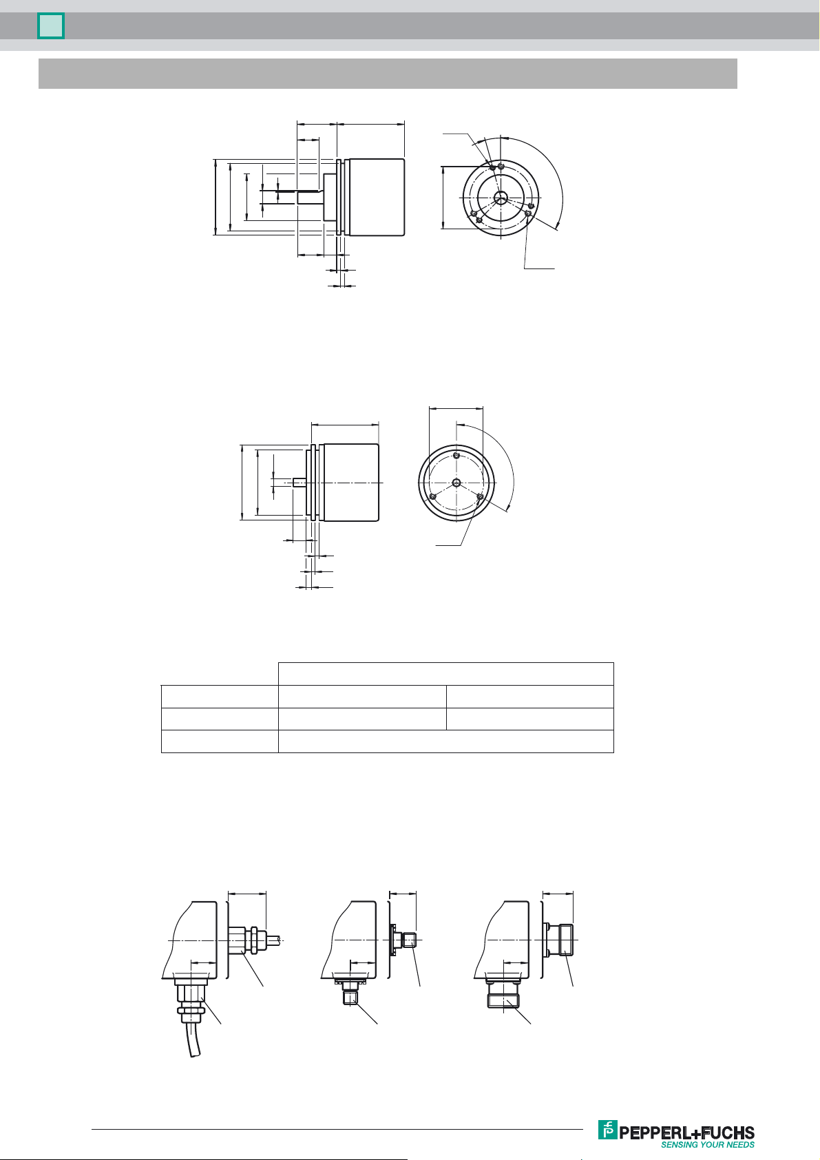
Dimensions
ø10h8
ø53
ø58
ø36f7
Clamping flange
ø58
ø50f7
1
ø6h7
30 L
18
20 10
L
3 x M3
6 deep
ø48
3
3
15°
3 x 120°
3 x M4
6 deep
ø42
3 x 120°
10
3
3
4
3 x M4
6 deep
Servo flange
L [mm]
Design Axial output Radial output
Singleturn 41.7
52.7
Multiturn 52.7
Connections
Dimensions in mm
Cable Connector M23Connector M12
~28
21
25
21~18
exit position axial
exit position radial
Release date: 2017-09-28 14:52 Date of issue: 2017-09-28 t166164_eng.xml
exit position axial
exit position radial
Refer to “General Notes Relating to Pepperl+Fuchs Product Information”.
17.5
exit position axial
exit position radial
2
Absolute encoders ENA58IL-S***-SSI
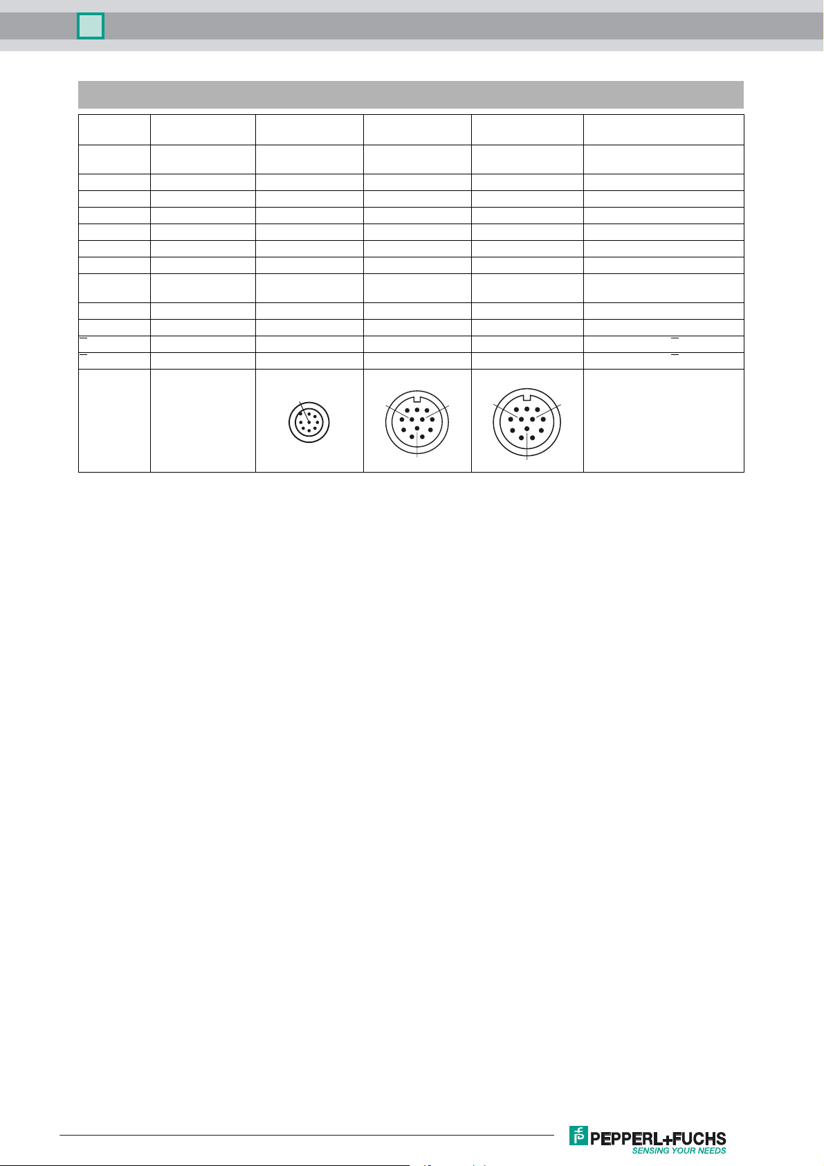
Electrical connection
Signal
GND (encoder)
(encoder)
U
b
Clock (+)
Clock (-)
Data (+)
Data (-)
A
V/R
PRESET 1
B
A
B
Cable, 12-core
Connector
M12, 8-pin
Connector
M23, 12-pin, cw
M23, 12-pin, ccw
White 1 1 1
Brown 2 2 8
Green 3 3 3
Yellow 4 4 11
Grey 5 5 2
Pink 6 6 10
Black 7 12
Red 8 8 5
Blue 7 9 9
Grey/Pink 10 4
Violet 11 6
Red/Blue 12 7
9
1
8
7
2
6
53
4
8
12
7
6
1
4
5
11
10
10
2
2
3
3
Connector
9
1
5
4
11
Explanation
Power supply
Power supply
Positive cycle line
Negative cycle line
Positive transmission data
Negative transmission data
Incremental track A
Input for selection of counting di-
rection
Zero-setting input
Incremental track B
Incremental track A
Incremental track B
8
12
7
6
Release date: 2017-09-28 14:52 Date of issue: 2017-09-28 t166164_eng.xml
Refer to “General Notes Relating to Pepperl+Fuchs Product Information”.
3

Absolute encoders ENA58IL-S***-SSI
Signal outputs
! cw - with view onto the shaft
A
A
B
B
Release date: 2017-09-28 14:52 Date of issue: 2017-09-28 t166164_eng.xml
Refer to “General Notes Relating to Pepperl+Fuchs Product Information”.
4

Absolute encoders ENA58IL-S***-SSI
Description
The Synchronous Serial Interface was specially developed for transferring the output data of an absolute encoder to a control device. The control module
sends a clock bundle and the absolute encoder responds with the position value.
Thus only 4 lines are required for the clock and data, no matter what the resolution of the rotary encoder is. The RS 422 interface is optically isolated from the
power supply.
SSI signal course Standard
Clock +
Data +
T
D
n
MSB
D1, ..., Dn:T = 1/f:
S:
MSB:
LSB:
D
n-1
Position data
Special bit
Most significant bit
Least significant bit
D
n-2
D
n-3
D
2
D
1
S
LSB
:
T
m
:
T
p
Duration of period of clock signal
Monoflop time 20 µs ± 1 µs
Clock pause
T
p
T
m
≥ monoflop time (Tp ≥ T
≤ 1 MHz
)
m
SSI output format Standard
• At idle status signal lines "Data +" and "Clock +" are at high level (5 V).
• The first time the clock signal switches from high to low, the data transfer in which the current information (position data (Dn) and special bit (S)) is
stored in the encoder is introduced.±
• The highest order bit (MSB) is applied to the serial data output of the encoder with the first rising pulse edge.
• The next successive lower order bit is transferred with each following rising pulse edge.
• After the lowest order bit (LSB) has been transferred the data line switches to low until the monoflop time Tm has expired.
• No subsequent data transfer can be started until the data line switches to high again or the time for the clock pause Tp has expired.
• After the clock sequence is complete, the monoflop time Tm is triggered with the last falling pulse edge.
• The monoflop time Tm determines the lowest transmission frequency.
SSI output format ring slide operation (multiple transmission)
• In ring slide operation, multiple transmission of the same data word over the SSI interface makes it possible to offer the possibility of detecting
transmission errors.
• In multiple transmission, n bits are transferred per data word in standard format. The value n equals the total resolution of the encoder.
As an example: a multiturn encoder with a resolution of 8192 steps/revolution (13 bit) and a max. number of 4096 revolutions (12 bit) has a total
resolution of n = 25 bit.
• If the clock change is not interrupted after the last falling pulse edge, ring slide operation automatically becomes active. This means that the information
that was stored at the time of the first clock change is generated again.
• After the first position transmission, the n+1 pulse controls data repetition. If the n+1 pulse follows after an amount of time greater than the monoflop
time Tm, a new current data word will be transmitted with the following pulses.
If the pulse line is exchanged, the data word is generated offset.
Block diagram Line length
Data +
Data -
Logic
Clock +
Clock -
Rotary encoder Interface electronics
Release date: 2017-09-28 14:52 Date of issue: 2017-09-28 t166164_eng.xml
Refer to “General Notes Relating to Pepperl+Fuchs Product Information”.
Receiver
Clock
generator
Line length in m Baudrate in kHz
< 50 < 400
< 100 < 300
< 200 < 200
< 400 < 100
5

Absolute encoders ENA58IL-S***-SSI
Push buttons on encoder with model characteristic SB2, SG2
In addition to the electrical preset function (PRESET 1) these models are equipped with 2 push buttons for manually setting the zero point of the rotary encoder.
Manually zero set
1. Simultaneously press and hold the push buttons A and B for 2 s.
After releasing the push buttons the rotary encoder sets the current position as zero point.
Model number
ENA5 8 I L - S - -
Connection type
C1 Cable, 1 m
C2 Cable, 2 m
C5 Cable, 5 m
CA Cable, 10 m
AA M23 device plug, cw
AB M23 device plug, ccw
M12 device plug, 8-pin (not
BE
available with SSI +
incremental track)
Connection alignment
A axial
R radial
Electical interface
SG1 ... SIC see next page
Singleturn resolution
12 12 bit
13 13 bit
16 16 bit
Multiturn resolution
00 Singleturn rotary encoder
12 Multiturn rotary encoder, 12 bit
14 Multiturn rotary encoder, 14 bit
16 Multiturn rotary encoder, 16 bit
Degree of protection
5 IP65
7 IP67 (not for M23 device plug)
Flange
CA Clamping flange
SA Servo flange
Shaft diameter
06 6 mm
10 10 mm
Shaft type
S Solid shaft
Ver si on
IL Industrial Line
Size
58 Housing diameter: 58 mm
Device type
ENA Absolute rotary encoder
Release date: 2017-09-28 14:52 Date of issue: 2017-09-28 t166164_eng.xml
Refer to “General Notes Relating to Pepperl+Fuchs Product Information”.
6

Absolute encoders ENA58IL-S***-SSI
ENA5 8 I L - S - -
Electical interface
SG1 SSI Gray
SB1 SSI binary
SG2 SSI Gray, with push buttons
SB2 SSI binary, with push buttons
SI1 SSI Gray + 1024 pulses, Push/Pull
SI2 SSI Gray + 2048 pulses, Push/Pull
SI3 SSI Gray + 4096 pulses, Push/Pull
SI4 SSI Gray + 1024 pulses, RS422
SI5 SSI Gray + 2048 pulses, RS422
SI6 SSI Gray + 4096 pulses, RS422
SI7 SSI Binär + 1024 pulses, Push/Pull
SI8 SSI Binär + 2048 pulses, Push/Pull
SI9 SSI Binär + 4096 pulses, Push/Pull
SIA SSI Binär + 1024 pulses, RS422
SIB SSI Binär + 2048 pulses, RS422
SIC SSI Binär + 4046 pulses, RS422
Release date: 2017-09-28 14:52 Date of issue: 2017-09-28 t166164_eng.xml
Refer to “General Notes Relating to Pepperl+Fuchs Product Information”.
7
 Loading...