

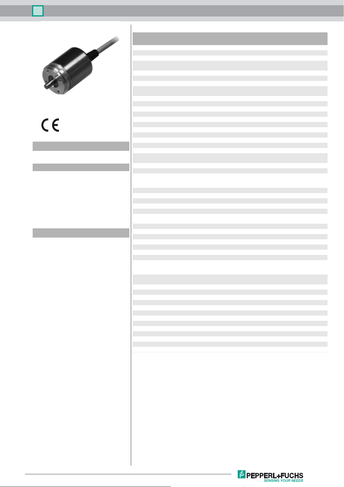
Multiturn absolute encoder ENA36IL-S***-Analog
Technical data
General specifications
Detection type magnetic sampling
Device type Absolute encoders
Model Number
ENA36IL-S***-Analog
Features
• Very small housing
• High climatic resistance
• 4 Bit multiturn
• Models with analog voltage or
current output
•Surge and reverse polarity
protection
Description
This absolute encoder with internal magnetic
sampling is available with an analog voltage output
or an analog current output. Depending on the
model, the analog output provides a voltage value
or a current value corresponding to the shaft setting.
The encoder can be easily programmed by means
of electrical inputs and push buttons.
Measurement range min. 0 ... 22.5 °
Resolution 17 Bit (13 bits/revolution)
Electrical specifications
Operating voltage U
Current consumption typ. 15 mA (with voltage output)
Input 1
Input type lower limit of measurement range
Signal voltage
High 8 ... 32 V DC
Signal duration ≥ 1 s
Input 2
Input type upper limit of measurement range
Signal voltage
High
Signal duration ≥ 1 s
Analog output
Output type analog voltage output or analog current output (see type
Default setting rising ramp at ccw rotation
Linearity error ≤ 0.15 %
Load resistor min. 5000 Ω (with voltage output) , min. 500 Ω (with current
Connection
Connector M12 connector, 5 pin
Cable Ø6 mm, 4 x 2 x 0.14 mm2, 1 m
Standard conformity
Degree of protection acc. DIN EN 60529
Connection side cable models: IP54
Shaft side IP65
Climatic testing DIN EN 60068-2-3, no moisture condensation
Emitted interference EN 61000-6-4:2007
Noise immunity EN 61000-6-2:2005
Shock resistance DIN EN 60068-2-27, 100 g, 6 ms
Vibration resistance DIN EN 60068-2-6, 10 g, 10 ... 1000 Hz
Ambient conditions
Operating temperature cable, flexing: -5 ... 70 °C (-23 ... 158 °F),
Storage temperature cable models: -30 ... 70 °C (-22 ... 158 °F)
Relative humidity 98 % , no moisture condensation
Mechanical specifications
Material
Housing nickel-plated steel
Flange
Shaft Stainless steel
Mass approx. 150 g , with cable
Rotational speed max. 12000 min
Moment of inertia 30 gcm
Starting torque < 3 Ncm
Shaft load
Axial 20 N
Radi
al 40
B
max. 16 x 360 °
8 ... 32 V DC
typ. 20 mA (with current output)
8 ... 32 V DC
code)
output) ; Max. value for supply voltage 8 V. For higher supply
voltage lower load resistance can be used.
connector models: IP65
cable, fixed: -30 ... 70 °C (-22 ... 158 °F)
connector models: -40 ... 85 °C (-40 ... 185 °F)
connector models: -30 ... 85 °C (-22 ... 185 °F)
inum
Alum
-1
2
N
Release date: 2017-05-16 09:40 Date of issue: 2017-05-16 t186711_eng.xml
Refer to “General Notes Relating to Pepperl+Fuchs Product Information”.
1
Multiturn absolute encoder ENA36IL-S***-Analog
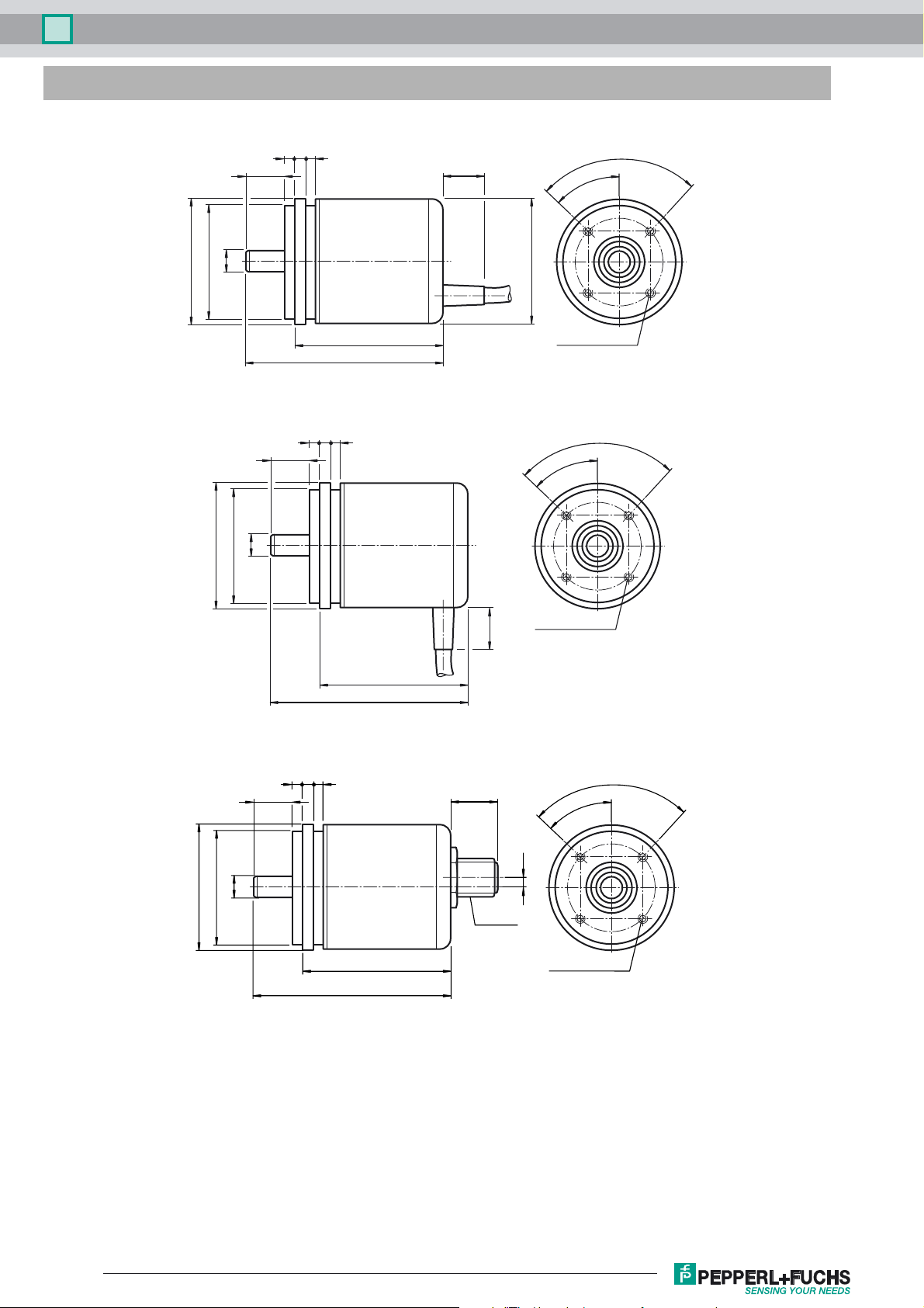
Dimensions
ø 33
ø 36.5
ø 6h6
ø 33
ø 36.5
11.5 ± 0.1
11.5 ± 0.1
ø 6h6
3 33
57.5 ± 0.5
3 33
90°
16
ø 36.5
43
45°
4 x M3 x 0.5, 6H
90°
45°
ø 33
ø 36.5
11.5 ± 0.1
ø 6h6
333
57.5 ± 0.5
57.5 ± 0.5
16
43
13
M12 x 1
43
4 x M3 x 0.5, 6H
90°
45°
3.5
4 x M3 x 0.5, 6H
Release date: 2017-05-16 09:40 Date of issue: 2017-05-16 t186711_eng.xml
Refer to “General Notes Relating to Pepperl+Fuchs Product Information”.
2

Multiturn absolute encoder ENA36IL-S***-Analog
36
10
ø 36.5
ø 33
11.5
ø 6
3 3 3
Electrical connection
Signal Wire end M12 connector
Analog output Green 1
(encoder) Red 2
+V
s
GND (encoder) Yellow 3
Set 2 White 4
Set 1 Brown 5
Shielding Screen Housing
1
5
Pinout -
2
4
ø 25
43.4
4 x M3
38
M12
3
Description of rotary encoder functions
Default Settings
Lower measuring range limit Mid measuring range Upper measuring range limit
Singleturn absolute
rotary encoder
Multiturn absolute
rotary encoder
Programming Encoders with No Operating Buttons
Scaling the measuring range
Use signal inputs "Set 1" and "Set 2" to scale the measuring range (minimum measuring range: 22.5°).
1. Connect signal inputs "Set 1" and "Set 2" simultaneously to +U
2. Turn the rotary encoder shaft to position 1 (lower measuring range limit).
3. Connect signal input "Set 1" to a high-potential source (+U
4. Connect signal input "Set 1" to ground
5. Turn the rotary encoder shaft to position 2 (upper measuring range limit).
6. Connect signal input "Set 2" to a high-potential source (+U
7. Connect signal input "Set 2" to ground
The analog output is now scaled to the programmed measuring range and the rotary encoder will operate in normal mode.
Resetting to the Default Setting
1. Connect the two signal inputs ("Set 1" and "Set 2") to a high-potential source (+U
The measuring range is then reset to the default setting.
Programming Encoders with Operating Buttons
Scaling the measuring range
Use operating buttons "Lim1" and "Lim2" to scale the measuring range (minimum measuring range: 22.5°).
1. Press the two operating buttons ("Lim1" and "Lim2") simultaneously. Both LEDs will light up. Press and hold the operating buttons for 15
seconds until the two LEDs start to flash. The rotary encoder is now in programming mode.
2. Turn the rotary encoder shaft to position 1 (lower measuring range limit).
3. Press and hold operating button "Lim1" for 1 second. The green LED will now light up permanently.
4. Turn the rotary encoder shaft to position 2 (upper measuring range limit).
5. Press and hold operating button "Lim2" for 1 second.
0180°360°
0 8 x 360° 16 x 360°
for 15 seconds. The progamming mode is activated now.
B
< high potential < +U
B min
< high potential < +U
B min
B min
) for 1 second.
B max
) for 1 second.
B max
< high potential < +U
) for 1 second.
B max
Release date: 2017-05-16 09:40 Date of issue: 2017-05-16 t186711_eng.xml
Refer to “General Notes Relating to Pepperl+Fuchs Product Information”.
3

Multiturn absolute encoder ENA36IL-S***-Analog
The analog output is now scaled to the programmed measuring range and the rotary encoder will operate in normal mode. Only the green LED
will light up.
Resetting to the Default Setting
1. Press the two operating buttons ("Lim1" and "Lim2") simultaneously. Both LEDs will light up. Press and hold the operating buttons for 30
seconds. After 15 seconds, the two LEDs will start to flash.
When the green LED goes out and the yellow LED lights up permanently, the measuring range is reset to the default setting.
Status LEDs
The rotary encoder is equipped with two status LEDs. These LEDs have three possible states: off, flashing, or on. The LEDs use different combinations of these states to indicate the status of the rotary encoder.
Yellow LED Green LED Description
On Off Rotary encoder operation using default settings
Off On Rotary encoder operation using scaled measuring range (customer-
specific setting)
On On Programming mode initiated (temporary state)
Flashes Flashes Rotary encoder in programming mode
On Flashes Position 2 set, waiting for position 1
Flashes On Position 1 set, waiting for position 2
Analog Output Properties
LED GN
Lim1 Lim2
Depending on its design, the rotary encoder projects the current angular position of the rotary encoder shaft in an analog current or voltage value.
The following graphic shows the values the output accepts at the various angular positions:
Analog output
D
C
LED YE
default
scaled
Mid
B
A
12 345
Mid
Posi tion
Legend:
Encoder type
1)
Factor y
12Mid34 5
0° - 180° - 360° -
Angular position
default
Singleturn
setting
Scaled
Factor y
0° Lower measuring
range limit
0° -
-Upper measuring
4
2
x 180°
range limit
default
Multiturn
setting
Scaled
0° Lower measuring
2)
range limit
-Upper measuring
range limit
n = whole number from 1 to 16
1) See model number
2) Overflow at 360°, 720°, 1440°, 2880°, 5760°, etc. depending on the scale set.
Encoder output type
0 V ... 5 V
0.5 V ... 4.5 V
0 V ... 10 V
0.5 V ... 9.5 V
4 mA ... 20 mA
0 mA ... 20 mA
ABMidCD
- 0 V2.5 V5 V -
0.25 V 0.5 V 2.5 V 4.5 V 4.75 V
-0 V5 V10 V-
0.25 V 0.5 V 5 V 9.5 V 9.75 V
3.6 mA 4 mA 12 mA 20 mA 22 mA
- 0 mA 10 mA 20 mA -
Analog output value
360° Lower measuring
-
24 x 360°
n
2
x 360°
range limit
Lower measuring
range limit
Release date: 2017-05-16 09:40 Date of issue: 2017-05-16 t186711_eng.xml
Refer to “General Notes Relating to Pepperl+Fuchs Product Information”.
4

Multiturn absolute encoder ENA36IL-S***-Analog
Model number
ENA3 6 I L - S 0 6SA - 1 3 -
Connection type
C1 Cable, 1 m
C2 Cable, 2 m
C5 Cable, 5 m
CA Cable, 10 m
BD M12 device plug, 5-pin
Connection alignment
A axial
R radial
Interface, electric
U01 0 ... 10 V
U04 0.5 ... 4.5 V
U05 0 ... 5 V
U09 0.5 ... 9.5 V
UP1 0 ... 10 V with push buttons
UP4 0.5 ... 4.5 V with push buttons
UP5 0 ... 5 V with push buttons
UP9 0.5 ... 9.5 V with push buttons
I02 0 ... 20 mA
I42 4 ... 20 mA
IP0 0 ... 20 mA with push buttons
IP4 4 ... 20 mA with push buttons
Singleturn resolution
13 13 bit
Multiturn resolution
00 Singleturn rotary encoder
04 Multiturn rotary encoder, 4 bit
Degree of protection
4 IP54
5 IP65
Flange
SA Servo flange
Shaft diameter
06 6 mm
Shaft type
S Solid shaft
Vers io n
IL Industrial Line
Size
36 Housing diameter: 36 mm
Device type
ENA Absolute rotary encoder
Release date: 2017-05-16 09:40 Date of issue: 2017-05-16 t186711_eng.xml
Refer to “General Notes Relating to Pepperl+Fuchs Product Information”.
5
 Loading...