

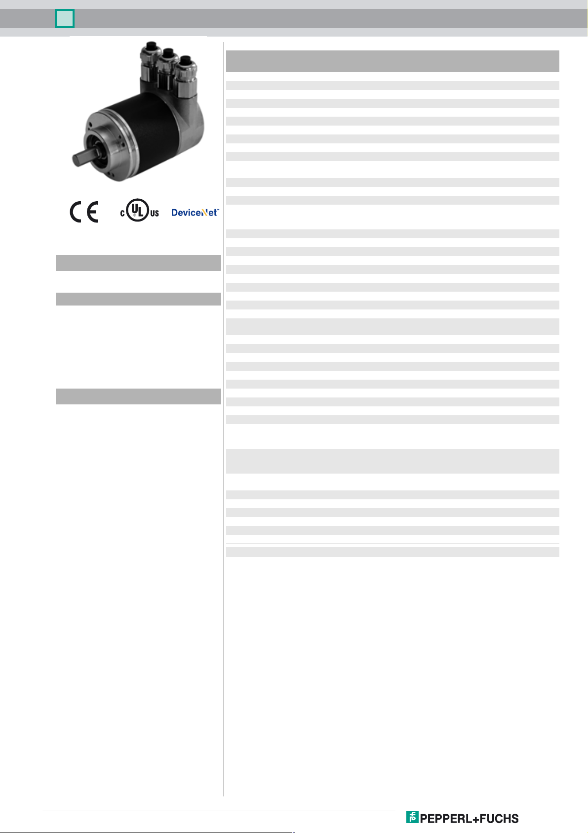
Multiturn absolute encoder DVM58
Technical Data
General specifications
Detection type photoelectric sampling
Device type Multiturn absolute encoder
Functional safety related parameters
MTTFd 70 a
Mission Time (TM) 20 a
L
1.9 E+11 at 6000 rpm and 20/40 N axial/radial shaft load
10
Diagnostic Coverage (DC) 0 %
Electrical specifications
Model Number
DVM58
Features
• Industrial standard
housing Ø58 mm
•30 Bit multiturn
• Galvanically isolated DeviceNet
interface
•Servo or clamping flange
Description
In addition to the CANopen, PROFIBUS and ASInterface rotary encoders, we have broadened our
product line of bus-capable absolute encoders with
the DVM58 for DeviceNet.
The bus electronics module is integrated into the
removable housing cover. This makes it possible to
mount or replace the new rotary encoders and the
matching bus electronics separately during
installation or service.
Absolute encoders deliver an absolute step value
for each angle setting. All these values are
represented by code samples on one or more code
disks. The code disks are screened by an infrared
LED and the bit obtained sample is detected by an
optical array. Its signals are electronically amplified
and are forwarded on to the interface for
processing.
The absolute encoder has a maximum basic
resolution of 65536 steps per revolution (16 Bits). In
the multiturn design, additional up to
16384 revolutions (14 Bits) can be resolved. This
results in a total maximum resolution of
1073741824 steps (30 Bits).
The integrated CAN bus interface of the absolute
encoder supports all DeviceNet functions. The
following operating modes can be programmed,
and can be selectively turned on or off:
• Polled mode
• Change of state mode
•Cyclic mode
The device is designed for shaft assembly and is
available in servo flange or clamping flange design.
Operating voltage U
No-load supply current I
Time delay before availability t
Linearity ± 2 LSB at 16 Bit, ± 1 LSB at 13 Bit, ± 0,5 LSB at 12 Bit
Output code binary code
Code course (counting direction) cw ascending (clockwise rotation, code course ascending)
Interface
Interface type DeviceNet
Resolution
Single turn up to 16 Bit
Multiturn 14 Bit
Overall resolution up to 30 Bit
Transfer rate max. 0.5 MBit/s
Connection
Terminal compartment in removable housing cover
Standard conformity
Degree of protection DIN EN 60529, IP65
Climatic testing DIN EN 60068-2-30 , no moisture condensation
Emitted interference DIN EN 61000-6-4
Noise immunity DIN EN 61000-6-2
Shock resistance DIN EN 60068-2-27, 100 g, 6 ms
Vibration resistance DIN EN 60068-2-6, 20 g, 10 ... 2000 Hz
Ambient conditions
Operating temperature -40 ... 85 °C (-40 ... 185 °F)
Storage temperature -40 ... 85 °C (-40 ... 185 °F)
Mechanical specifications
Material
Combination 1 housing: powder coated aluminum
Combination 2 (Inox) housing: stainless steel
Mass approx. 700 g (combination 1)
Rotational speed max. 12000 min
Moment of inertia 30 gcm
Starting torque ≤ 3 Ncm (version without shaft seal)
Shaft load
Axial 40 N
Radial 110 N
Approvals and certificates
UL approval cULus Listed, General Purpose, Class 2 Power Source
B
0
v
10 ... 30 V DC
max. 230 mA at 10 V DC
max. 100 mA at 24 V DC
< 250 ms
cw descending (clockwise rotation, code course
descending)
IP66 (with shaft seal)
flange: aluminum
shaft: stainless steel
flange: stainless steel
shaft: stainless steel
approx. 1200 g (combination 2)
-1
2
Release date: 2019-04-11 06:55 Date of issue: 2019-04-11 t49157_eng.xml
Refer to "General Notes Relating to Pepperl+Fuchs Product Information".
1
Multiturn absolute encoder DVM58
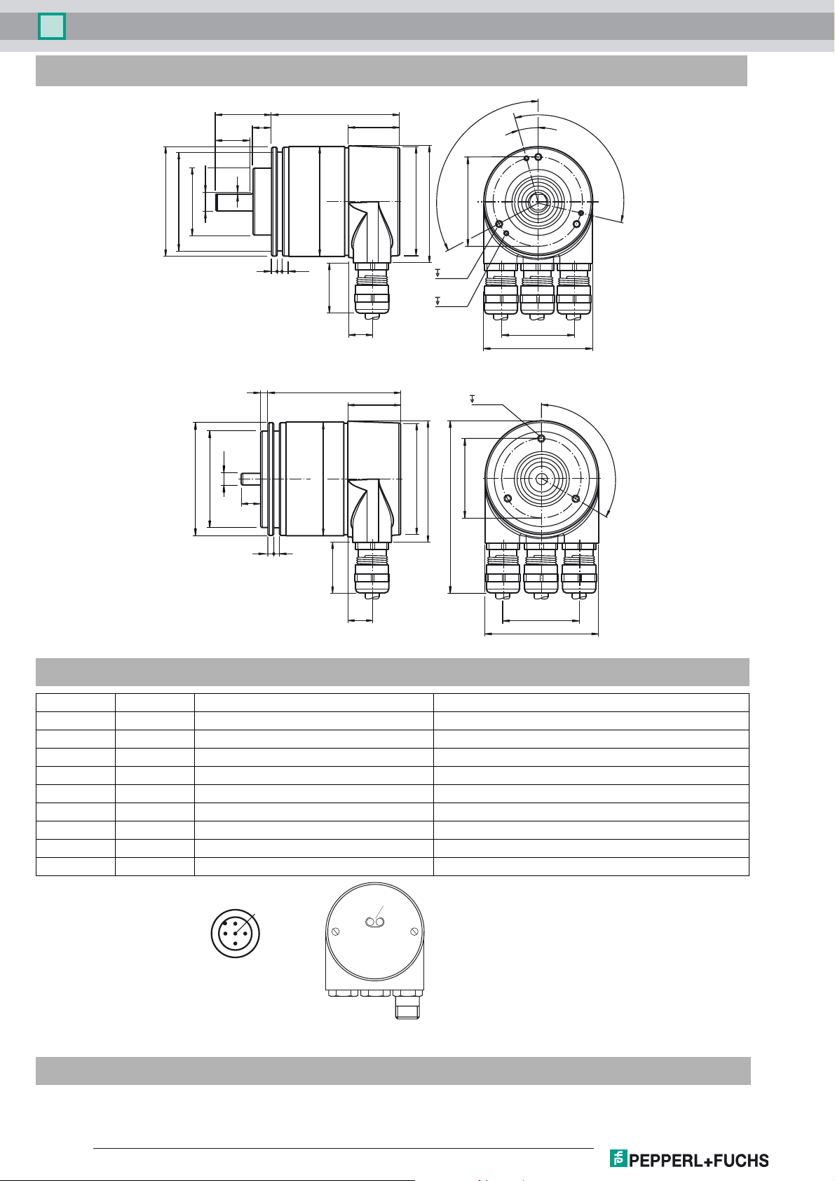
Dimensions
30 L
10
18
1
10h8
ø 58
ø 53
36f7
3 3.5
* Singleturn: L = 69, Multiturn : L = 80
** Aluminum: d = 59, stainless steel: d = 61
4
6f6
ø 58
ø 50f7
10
d**
3
25
L
d**
12.7
27.5
27.5
ø 58
ø 58
3 x 120°
63
M4 x 0.7
6
M3 x 0.5
6
63
88
TK ø 48
M4 x 0.7
6
TK ø 42
15°
3 x 120°
40
60
3 x 120°
3
3
25
* Singleturn: L = 69, Multiturn : L = 80
** Aluminum: d = 59, stainless steel: d = 61
-
12.7
40
60
Electrical connection
Terminal Cable M12 x 1 Connector Explanation
⊥ - - Ground connection for power supply
(+) Red 2 Power supply
(-) Black 3 Power supply
CG - 1 CAN ground
CL Blue 5 CAN low
CH White 4 CAN high
CG - - CAN ground
CL Blue - CAN low
CH White - CAN high
1
5
2
4
LEDs
3
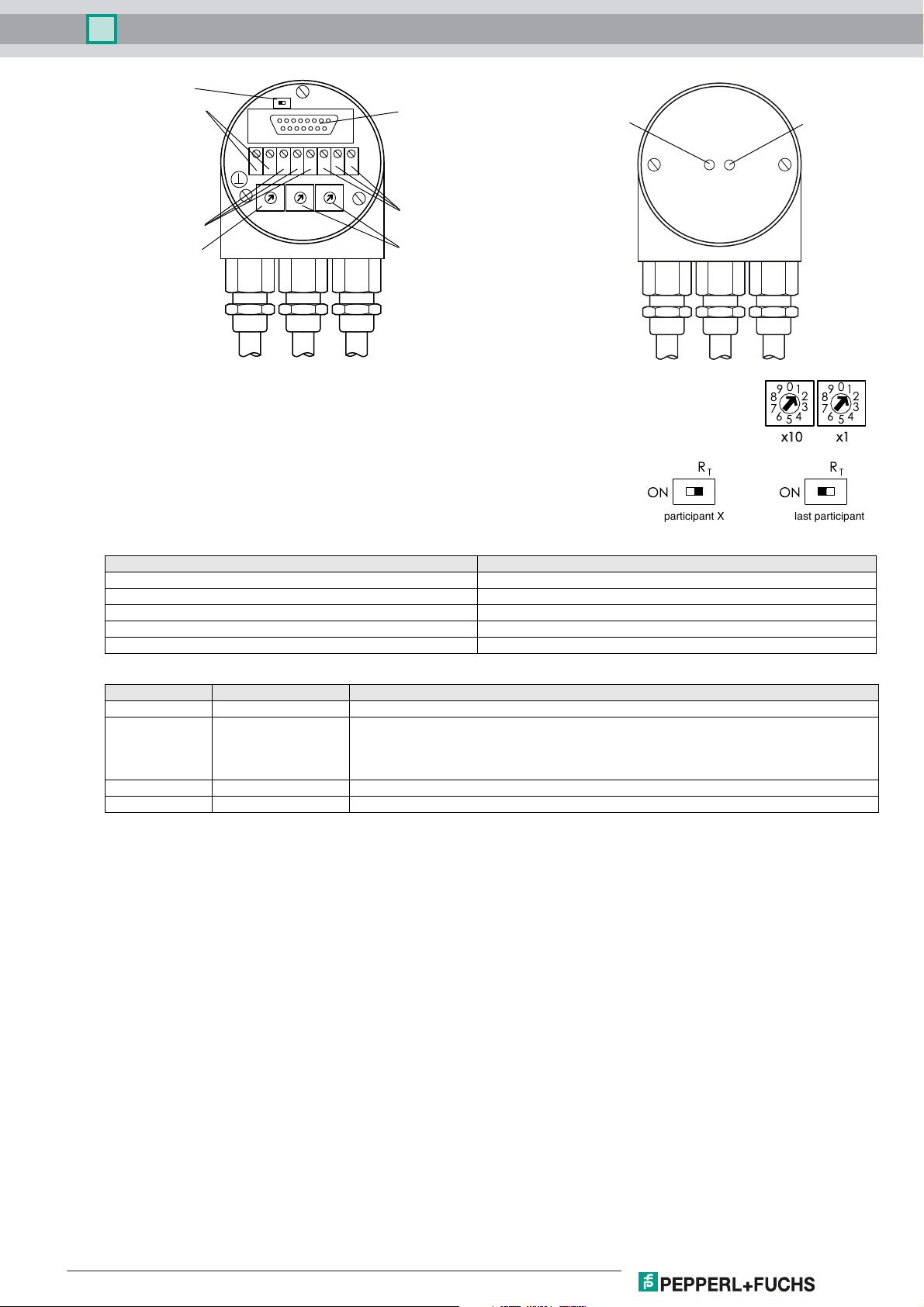
Indicating and operating elements
Refer to "General Notes Relating to Pepperl+Fuchs Product Information".
2
Release date: 2019-04-11 06:55 Date of issue: 2019-04-11 t49157_eng.xml
Multiturn absolute encoder DVM58
Termination resistor
Supply voltage
R
T
ON
RS 485 interface
Error indicator
LED green
LLH
-+
0
9 1
8
7
4
6
5
Bus In
Baud rate
2
G
H
G
0
0
9 1
9 1
2
2
8
3
7
2
8
3
3
7
4
4
6
6
5
5
x1
x10Bd
Bus Out
Addressing
Adjusting the participant address
The participant address can be adjusted with the rotary switches. The address can be defined
between 1 and 63, and may only be assigned once.
Adjusting the termination resistor
R
The terminating resistor R
of the switch:
(121 Ω) can be connected to the circuit by means
T
ON
T
participant X last participant
Baud rate adjustment
Baud rate [kBit/s] Switch position
125 0
250 1
500 2
125 3
reserved 4 ... 9
LED-indicators
LED red LED green Meaning
off off No voltage supply
off on Encoder ready, boot-up message not transmitted, yet. Possible reasons:
- no further participant present
- wrong baud rate
- encoder in prepared status
flashing on Boot-up message transmitted, Device configuration possible.
on on Normal operation mode, encoder in operational status.
Status indicator
LED green
StaErr
'
&
%
$
#
'
!
"
&
!
%
"
$
#
N N
R
T
ON
Release date: 2019-04-11 06:55 Date of issue: 2019-04-11 t49157_eng.xml
Refer to "General Notes Relating to Pepperl+Fuchs Product Information".
3

Multiturn absolute encoder DVM58
Programmable CAN operating modes
Mode Explanation
Polled mode
Cyclic mode
Change of state mode
Programmable rotary encoder parameters
Parameter Explanation
Operating parameter
Resolution per revolution
Overall resolution
Preset value
The connected host requests the current actual position value via a telegram. The absolute encoder reads in
the current position, calculates all parameters that may have been set and then sends back the actual process
value.
The absolute encoder sends the current process value depending on a programmable timer. This can cause the
bus load to be reduced since the member on the network only sends a message after a specific amount of time
without a prompt from the master.
The absolute encoder monitors the current process value and transfers the current value by itself if there is any
change in the value. This can cause the bus load to be reduced, since the member on the network only sends
a message if there has been a change.
The direction of rotation (complement) can be specified by parameter as the operating parameter. This
parameter determines the direction of rotation in which the output code will be rising or descending.
The "Resolution" parameter is used to program the rotary encoder so that a desired number of steps can be
implemented in reference to a revolution.
This parameter indicates the desired number of measurement units of the entire travel length. This value must
not exceed the overall resolution of the absolute encoder. If the absolute encoder is used in infinite mode, the
overall resolution parameter can only take on values that are powers of 2 (2x).
The preset value is the desired position value that must be achieved for a specific physical setting of the axis.
The preset value parameter is used to set the actual position value to the desired actual process value.
Accessories
For type Accessories Name/defining feature Order code
D1: Ø10 mm, D2: Ø10 mm 9401
Couplings
Measurement wheels with
DVM58N-011
DVM58N-032
For additional information on the accessories, please see the "Accessories" section.
circumference of 500 mm
Measurement wheels with
circumference of 200 mm
Mounting aids
Couplings
Mounting aids
D1: Ø10 mm, D2: Ø10 mm 9404
D1: Ø10 mm, D2: Ø10 mm 9409
D1: Ø10 mm, D2: Ø10 mm KW
Plastic 9101, 10
Pimpled rubber 9102, 10
Knurled aluminium 9103, 10
Knurled plastic 9112, 10
Plastic 9108, 10
Pimpled rubber 9109, 10
Knurled aluminium 9110, 10
Knurled plastic 9113, 10
Mounting bracket 9203
Mounting bracket 9213
D1: Ø6 mm, D2: Ø6 mm 9401
D1: Ø6 mm, D2: Ø6 mm 9402
D1: Ø6 mm, D2: Ø6 mm 9404
D1: Ø6 mm, D2: Ø6 mm 9409
D1: Ø6 mm, D2: Ø6 mm KW
Mounting bracket and set 9300 and 9311-3
Eccentric clamping elements 9310-3
Release date: 2019-04-11 06:55 Date of issue: 2019-04-11 t49157_eng.xml
Refer to "General Notes Relating to Pepperl+Fuchs Product Information".
4

Multiturn absolute encoder DVM58
Order code
DVM58 – R0BN–
Number of bits singleturn
12 4096 (standard)
13 8192
16 65536
Number of bits multiturn
12 4096 (standard)
14 16384
Option 2
N Not expanded
Output code
B Binary
Option 1
0 No option
Exit position
R Radial
Connection type
AG Removable housing cover with terminal compartment
AN Removable housing cover with connectors M12x1
Shaft dimension/flange version
011 Shaft Ø10 mm x 20 mm with clamping flange
032 Shaft Ø6 mm x 10 mm with servo flange
Housing material
N Aluminium, powder coated
I Inox
W Aluminium, powder coated with shaft seal
Principle of operation
M Multiturn
Shaft version
V Solid shaft
Data format
D DeviceNet
Release date: 2019-04-11 06:55 Date of issue: 2019-04-11 t49157_eng.xml
Refer to "General Notes Relating to Pepperl+Fuchs Product Information".
5
 Loading...